H2flo KIT-VOL160TS3TCP Guide d'installation
- Catégorie
- Articles sanitaires
- Taper
- Guide d'installation

IBKIT-VOL160TS3TCP_v201006
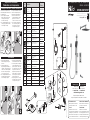
CARE INSTRUCTIONS
Rinse the product with clear water.
Dry the product with a soft cloth.
DO NOT:
Use abrasive cleansers, cloths, or
paper towels. Use any cleaning agents
containing acid, polish, wax, alcohol,
ammonia, bleach, solvent or any other
corrosive or harsh chemical cleansers.
INSTRUCTIONS D’ENTRETIEN
Rincer le robinet avec de l’eau claire
et l’essuyer avec un tissu doux.
À NE PAS FAIRE :
Utiliser des tissus ou essuie-tout
abrasifs, produits nettoyants contenant
de l’acide, agent polisseur, cires, alcool,
ammoniaque, eau de Javel, solvants ou
tout autres produits chimiques corrosifs.
Customer Service
Monday to Friday:
8 a.m. - 4:30 p.m. E.S.T.
Tel: 1-800-361-5960
Service à la clientèle
Lundi au vendredi :
8 h 00 à 16 h 30 H.N.E.
Fax : 1-888-533-8313
clientinf[email protected]
Replacement parts are available on order
Les pièces de remplacement sont disponibles sur commande
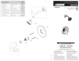
KIT: SHOWER FAUCET - TRIM / KIT : ROBINET POUR
DOUCHE - GARNITURE
KIT-VOL160TS3TCP
B1
A7
A4
A5
B2
A6
A2
A3
D
F
E
C
B3
B
A
G
A8
A1
G1 G3
G2
G4
B1
A7
A4
A5
B2
A6
A2
A3
D
F
E
C
B3
B
A
G
A8
A1
G1 G3
G2
G4
B1
A7
A4
A5
B2
A6
A2
A3
D
F
E
C
B3
B
A
G
A8
A1
G1 G3
G2
G4
For warranty and to register your product
Garantie et enregistrement de votre produit
belangerH2O.com
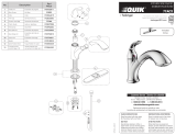
No Description Part
Pièce
AValve - Trim for
Thermostatic
Diverter Valve
Valve - Garniture pour
valve thermostatique,
déviatrice
VOL98TS3TCP
A-1 Thermostatic
handle kit
Ensemble de poignée
pour valve thermostatique FCKTS2128
A-2 Index Index FCHDL4017
A-3 Allen screw Vis Allen 923001
A-4 Trim sleeve Douille de finition FCDEC5017
A-5 Face plate
with seal
Plaque de finition avec
joint d’étanchéité FCDEC7096
A-6 O-Ring
(2.65mm x 48.70mm)
Joint torique
(2.65mm x 48.70mm) FCORA1039
A-7 Diverter
trim sleeve
Douille de finition
pour inverseur FCDEC5018
A-8 Diverter
handle kit
Ensemble de poignée
pour inverseur FCKTS2130
BSliding bar kit with
flexible hose
Ensemble de barre à
glissière et boyau B90-830
B-1 Flexible hose Boyau 96179
B-2 Hand shower
holder
Support pour douche
à main B93-800
B-3 Wall support Support murale B93-801
CHand shower
(1,8 gpm)
Douche à main
(1,8 gpm) FCSPS2039
DWater supply
elbow Coude d’alimentation B92-003
EShower arm
and flange kit
Ensemble de bras
et bride de douche FCDEC0015
FShower head Pomme de douche FCSPS3034
GSpout Bec de bain FCSPS6022
G-1 Aerator Aérateur FCAER3022
G-2 O-ring
(15mm x 2.5mm)
Joint torique
(15mm x 2.5mm) FCORA1033
G-3 Spout screw Vis du bec FCSCR2002
G-4 Flange Screw Vis de la bride FCSCR1004
2
1 2
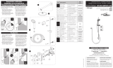
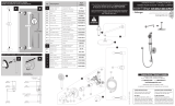
Temperature calibration
Calibration de la température
1
1. Remove the temperature handle
from the cartridge by loosening the
Allen screw.
2. Turn water on and measure its
temperature using a thermometer. If it
is below 38˚C, turn the spindle slightly
counterclockwise. If the temperature is
above 38˚C, turn the spindle slightly
clockwise, until you reach 38˚C.
3. Place the temperature handle back on
the spindle aligning the button with
the “38˚C” marking on the plate.
1. Retirer la poignée de température de
la cartouche en dévissant la vis Allen.
2. Ouvrir l’eau et prendre sa température
à l’aide d’un thermomètre. Si elle est
plus basse que 38˚C, tourner l’arbre
de la cartouche dans le sens contraire
des aiguilles d’une montre. Si la
température est plus haute que 38˚C,
tourner l’arbre de la cartouche dans
le sens des aiguilles d’une montre,
jusqu’à l’obtention de 38˚C.
3. Replacer la poignée sur la cartouche
en alignant sa tige avec l’inscription
« 38˚C » présent sur la plaque.
The valve has a security button at 38˚C,
however the temperature can be adjusted
to a maximum of 43˚C.
1. Before securing the temperature
handle, align the black lines on the
cartridge body and the spindle;
this calibrates the cartridge.
2. Place the temperature handle on the
cartridge, aligning the button with the
“38˚C” marking on the plate.
La valve possède une butée de sécurité
à 38˚C mais la température peut être
ajustée jusqu’à un maximum de 43˚C.
1. Avant de faire l’installation de la
poignée de température, aligner les
lignes noires sur la cartouche
et l’arbre; ceci calibre la cartouche.
2. Placer la poignée de température
sur la cartouche en alignant la tige
de la poignée avec l’inscription
« 38˚C » présent sur la plaque.
During the installation - Pendant l’installation
Recalibration
38º
3
SPINDLE
ARBRE

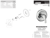
Technical drawing - Dessin technique
KIT-VOL160TS3TCP
v141121
IMPORTANT
Bélanger recommends using a professional plumber for all
installation and repair. Please inform yourself about the
Canadian Plumbing Code’s regulations and your local
municipality plumbing codes before installation. The Canadian
Plumbing Code requires the installation of surge arresting devices to eliminate water
hammering. ALLOW AN ADEQUATE OPENING IN ORDER TO EASILY ACCESS
CONNECTIONS OR OTHER PLUMBING DEVICES FOR MAINTENANCE OR REPAIR.
Bélanger recommande de faire appel à un plombier compétent pour l’installation
et la réparation de ce produit. Veuillez vous informer des différentes règles
du Code Canadien de plomberie et des exigences de votre localité avant
l’installation. Le Code Canadien de plomberie exige l’installation d’un dispositif
anti-bélier a n d’amortir les coups de bélier dans la plomberie. PRÉVOIR UNE
OUVERTURE SUFFISANTE POUR FACILITER L’ACCÈS AUX RACCORDEMENTS OU
À TOUT AUTRE DISPOSITIF DE PLOMBERIE EN VUE DE L’ENTRETIEN OU DE LA
RÉPARATION.
The model shown in the installation steps may
differ from the one in box however connection
type and installation steps are the same.
Le modèle démontré dans les étapes d’installation
peut différer du produit en boîte, mais le type
de connexions et d’installation demeure le même.
RECOMMENDED TOOLS / OUTILS RECOMMANDÉS
* Apply plumber’s putty under the plastic
cover deck plate to seal your installation.
Appliquez du mastic pour plombier
sous la sous-plaque de plastique
pour rendre votre installation étanche.
** Apply Bélanger thread seal tape
on threaded connections.
Appliquez du ruban d’étanchéité Bélanger
sur les connexions letées.
CONNECTION ADVICE
CONSEIL RACCORDEMENT
Firmly hand tighten the hose
to the valve and add a quarter-
turn using the proper wrench.
Tighten more if needed.
Raccordez le connecteur
exible à la valve
en serrant fermement
à la main puis ajoutez
un quart de tour à l’aide
de la clé appropriée.
Serrez plus au besoin.
Plumber’s putty
Mastic pour
plombier *
Thread seal tape
Ruban d’étanchéité
pour joints letés **
Included / Inclus
6-5/8”
(168 mm)
1-3/16”
(30 mm)
3-15/16”
(100 mm)
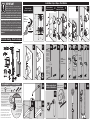
Installation steps - Étapes d’installation
Finished wall
mur ni
Floor
Plancher
1-3/16”
(30 mm)
5/8”
(15 mm)
4-11/16”
(119 mm)
30”
(762 mm)
31 3/16”
(792 mm)
2-11/16”
(68 mm)
3-7/8”
(98 mm)
9-1/16”
(230 mm) 2-9/16"
(65 mm)
2-9/16"
(65 mm)
1”
(25 mm)
1-9/16"
(39 mm)
3/8"
(10 mm)
2-1/4"
(57 mm)
Up to/Jusqu'à
3/4" (19 mm)
1-7/8"
(43 mm)
17-3/8”
(441 mm)
18-1/2”
(470 mm)
2-3/8”
(60 mm) 1-5/16”
(34 mm)
MIN 7/8” (22 mm)
MAX 1-7/8” (45 mm)
5-1/2”
(140 mm)
8-11/16”
(220 mm)
4-5/16”
(110 mm)
2-5/32”
(55 mm)
1-15/16”
(49 mm)
10-3/16”
(260 mm) 1-9/16”
(40 mm)
1-7/8”
(48 mm)
8-3/8”
(173 mm)
7-5/8”
(194 mm)
1Remove Guards
Enlever les guardes 2Finished sleeves
Manchons de nition 3
OFF
FERMÉ
Before you begin
Avant de commencer
MAIN WATER
VALVE
ENTRÉE D’EAU
PRINCIPALE
4 5
6 7
A
B
A
B
A
B
DRILL THROUGH
LOWER WALL ON
POINT “A”
PERCER LA
PARTIE
INFÉRIEURE DU
MUR AU POINT DE
PERÇAGE “A”
MEASURE AND
DRILL THROUGH
UPPER WALL
ON POINT “B”
MESURER ET
PERCER LA
PARTIE SUPÉRI-
EURE DU
MUR AU POINT
DE PERÇAGE “B”
SCREW
THE BRACKETS
SERRER
LES SUPPORTS
30”
(762 MM)
A
B
A
B
A
B
A
B
TIGHTEN
THE SCREWS
SERRER
LES VIS
PUSH
TO
ADJUST
HEIGHT
POUSSER
POUR
AJUSTER
LA HAUTEUR
A
B
8b8a 9 10 11 12 13
Water supply elbow
Coude d’alimentation BRIDE AJUSTABLE
ADJUSTABLE FLANGE
17
18 19 20
14
1615
-
 1
1
-
 2
2


H2flo KIT-VOL160TS3TCP Guide d'installation
- Catégorie
- Articles sanitaires
- Taper
- Guide d'installation
dans d''autres langues
Documents connexes
-
H2flo KAR92VTCP Guide d'installation
-
-
-
-
-
-
-
-
-
Autres documents
-
 Quik 92SVTCP Guide d'installation
-
 Quik 77AC2 Guide d'installation
-
Belanger 4799VTCP Guide d'installation
-
Keeney KITQUA140TSCP06 Guide d'installation
-
 Essential Style KIT-UNI140TSCP Guide d'installation
-
 Quik 92SVTCP2 Guide d'installation
-
-
 Essential Style KIT-DEL130CCP07 Guide d'installation
-
 Quik 99SVTCP2 Guide d'installation
-
ESSENTIAL EBA65WCP Guide d'installation


