Toro 127 cm TimeCutter MX 5075T Zero Turn Mower 74695 Manuel utilisateur
- Catégorie
- Tondeuses à gazon
- Taper
- Manuel utilisateur
Ce manuel convient également à

Form No. 3465-221 Rev A
T imeCutter
®
MR4275T or MR5075T Zero T urn Riding
Mower
74691 , 74695
T imeCutter
®
MR4275T oder MR5075T Nullwendekreis-
Aufsitzrasenmäher
74691 , 74695
T ondeuse autoportée à rayon de braquage zéro
T imeCutter
®
MR4275T ou MR5075T
74691 , 74695
T imeCutter
®
MR4275T en MR5075T zero-turn zitmaaier
74691 , 74695
www .T oro.com.
*3465-221*


Form No. 3465-205 Rev A
T imeCutter
®
MR4275T or
MR5075T Zero T urn Riding
Mower
Model No. 74691 —Serial No. 414500000 and Up
Model No. 74695 —Serial No. 414500000 and Up
Register at www .T oro.com.
Original Instructions (EN)
*3465-205*

This product complies with all relevant European
directives; for details, please see the separate product
specic Declaration of Conformity (DOC) sheet.
Gross or Net T orque: The gross or net torque
of this engine was laboratory rated by the engine
manufacturer in accordance with the Society of
Automotive Engineers (SAE) J1940 or J2723. As
congured to meet safety , emission, and operating
requirements, the actual engine torque on this class
of mower will be signicantly lower . Please refer to
the engine manufacturer ’ s information included with
the machine.
The enclosed engine owner's manual is supplied
for information regarding the US Environmental
Protection Agency (EP A) and the California Emission
Control Regulation of emission systems, maintenance,
and warranty . Replacements may be ordered through
the engine manufacturer .
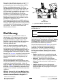
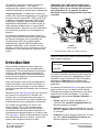
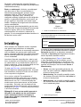
Introduction
This rotary-blade, riding lawn mower is intended to be
used by homeowners in residential applications. It is
designed primarily for cutting grass on well-maintained
lawns. Using this product for purposes other than
its intended use could prove dangerous to you and
bystanders.
Read this information carefully to learn how to operate
and maintain your product properly and to avoid
injury and product damage. Y ou are responsible for
operating the product properly and safely .
V isit www .T oro.com for product safety and operation
training materials, accessory information, help nding
a dealer , or to register your product.
Whenever you need service, genuine T oro parts, or
additional information, contact an Authorized Service
Dealer or T oro Customer Service and have the model
and serial numbers of your product ready . Figure 1
identies the location of the model and serial numbers
on the product. W rite the numbers in the space
provided.
Important: W ith your mobile device, you can
scan the QR code on the serial number decal (if
equipped) to access warranty , parts, and other
product information.
g297763
Figure 1
Under the seat
1. Model and serial number location
W rite the product model and serial numbers in the
space below:
Model No.
Serial No.
This manual uses 2 words to highlight information.
Important calls attention to special mechanical
information and Note emphasizes general information
worthy of special attention.
The safety-alert symbol ( Figure 2 ) appears both in
this manual and on the machine to identify important
safety messages that you must follow to avoid
accidents. This symbol will appear with the word
Danger ,W arning , or Caution .
•Danger indicates an imminently hazardous
situation which, if not avoided, will result in death
or serious injury .
•W arning indicates a potentially hazardous
situation which, if not avoided, could result in
death or serious injury .
•Caution indicates a potentially hazardous situation
which, if not avoided, may result in minor or
moderate injury .
sa-black
Figure 2
1. Safety-alert symbol
© 2023—The T oro® Company
81 1 1 L yndale A venue South
Bloomington, MN 55420
2
Contact us at www .T oro.com.
Printed in the USA
All Rights Reserved

Contents
Safety . . . . . . . . . . . . . . . . . . . . . . . . . . . . . . . . . . . . . . . . . . . . . . . . . . . . . . . . . . . . . . . . . . . . . . . 4
General Safety . . . . . . . . . . . . . . . . . . . . . . . . . . . . . . . . . . . . . . . . . . . . . . . . . . . 4
Slope Indicator . . . . . . . . . . . . . . . . . . . . . . . . . . . . . . . . . . . . . . . . . . . . . . . . . . . 5
Safety and Instructional Decals . . . . . . . . . . . . . . . . . . . . . . . . . . 6
Product Overview . . . . . . . . . . . . . . . . . . . . . . . . . . . . . . . . . . . . . . . . . . . . . . . . . . . 10
Controls . . . . . . . . . . . . . . . . . . . . . . . . . . . . . . . . . . . . . . . . . . . . . . . . . . . . . . . . . . . . 1 1
Specications . . . . . . . . . . . . . . . . . . . . . . . . . . . . . . . . . . . . . . . . . . . . . . . . . . 12
Attachments/Accessories . . . . . . . . . . . . . . . . . . . . . . . . . . . . . . . . . 12
Before Operation . . . . . . . . . . . . . . . . . . . . . . . . . . . . . . . . . . . . . . . . . . . . . . . . . 12
Before Operation Safety . . . . . . . . . . . . . . . . . . . . . . . . . . . . . . . . . . . 12
Adding Fuel . . . . . . . . . . . . . . . . . . . . . . . . . . . . . . . . . . . . . . . . . . . . . . . . . . . . . . 13
Performing Daily Maintenance . . . . . . . . . . . . . . . . . . . . . . . . . . 14
Breaking in a New Machine . . . . . . . . . . . . . . . . . . . . . . . . . . . . . . 14
Using the Safety-Interlock System . . . . . . . . . . . . . . . . . . . . 14
Positioning the Seat . . . . . . . . . . . . . . . . . . . . . . . . . . . . . . . . . . . . . . . . . . 15
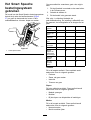
Adjusting the MyRide® Suspension
System . . . . . . . . . . . . . . . . . . . . . . . . . . . . . . . . . . . . . . . . . . . . . . . . . . . . . . . . . . 15
Adjusting the Motion-Control Levers . . . . . . . . . . . . . . . . . 15
Converting to Side Discharge . . . . . . . . . . . . . . . . . . . . . . . . . . . 16
During Operation . . . . . . . . . . . . . . . . . . . . . . . . . . . . . . . . . . . . . . . . . . . . . . . . . 18
During Operation Safety . . . . . . . . . . . . . . . . . . . . . . . . . . . . . . . . . . . 18
Operating the Mower Blade-Control Switch
(PT O) . . . . . . . . . . . . . . . . . . . . . . . . . . . . . . . . . . . . . . . . . . . . . . . . . . . . . . . . . . . . 20
Operating the Throttle . . . . . . . . . . . . . . . . . . . . . . . . . . . . . . . . . . . . . . . 21
Operating the Choke . . . . . . . . . . . . . . . . . . . . . . . . . . . . . . . . . . . . . . . . . 21
Starting the Engine . . . . . . . . . . . . . . . . . . . . . . . . . . . . . . . . . . . . . . . . . . . 21
Shutting Of f the Engine . . . . . . . . . . . . . . . . . . . . . . . . . . . . . . . . . . . . . 22
Using the Motion-Control Levers . . . . . . . . . . . . . . . . . . . . . . . 22
Driving the Machine . . . . . . . . . . . . . . . . . . . . . . . . . . . . . . . . . . . . . . . . . . 22
Using the Smart Speed
T M
Control
System . . . . . . . . . . . . . . . . . . . . . . . . . . . . . . . . . . . . . . . . . . . . . . . . . . . . . . . . . . 23
Using the Side Discharge . . . . . . . . . . . . . . . . . . . . . . . . . . . . . . . . . 24
Adjusting the Height of Cut . . . . . . . . . . . . . . . . . . . . . . . . . . . . . . . 24
Adjusting the Anti-Scalp Rollers . . . . . . . . . . . . . . . . . . . . . . . . 25
Operating T ips . . . . . . . . . . . . . . . . . . . . . . . . . . . . . . . . . . . . . . . . . . . . . . . . . 26
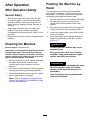
After Operation . . . . . . . . . . . . . . . . . . . . . . . . . . . . . . . . . . . . . . . . . . . . . . . . . . . . 27
After Operation Safety . . . . . . . . . . . . . . . . . . . . . . . . . . . . . . . . . . . . . . 27
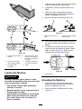
Cleaning the Machine . . . . . . . . . . . . . . . . . . . . . . . . . . . . . . . . . . . . . . . 27
Pushing the Machine by Hand . . . . . . . . . . . . . . . . . . . . . . . . . . 27
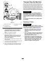
T ransporting the Machine . . . . . . . . . . . . . . . . . . . . . . . . . . . . . . . . . 28
Maintenance . . . . . . . . . . . . . . . . . . . . . . . . . . . . . . . . . . . . . . . . . . . . . . . . . . . . . . . . . . . 30
Maintenance Safety . . . . . . . . . . . . . . . . . . . . . . . . . . . . . . . . . . . . . . . . . . 30
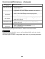
Recommended Maintenance Schedule(s) . . . . . . . . . . . 31
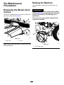
Pre-Maintenance Procedures . . . . . . . . . . . . . . . . . . . . . . . . . . . . . . 32
Releasing the Mower-Deck Curtain . . . . . . . . . . . . . . . . . . 32
Raising the Machine . . . . . . . . . . . . . . . . . . . . . . . . . . . . . . . . . . . . . . . . . 32
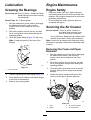
Lubrication . . . . . . . . . . . . . . . . . . . . . . . . . . . . . . . . . . . . . . . . . . . . . . . . . . . . . . . . . . 33
Greasing the Bearings . . . . . . . . . . . . . . . . . . . . . . . . . . . . . . . . . . . . . . 33
Engine Maintenance . . . . . . . . . . . . . . . . . . . . . . . . . . . . . . . . . . . . . . . . . . . 33
Engine Safety . . . . . . . . . . . . . . . . . . . . . . . . . . . . . . . . . . . . . . . . . . . . . . . . . . . 33
Servicing the Air Cleaner . . . . . . . . . . . . . . . . . . . . . . . . . . . . . . . . . . 33
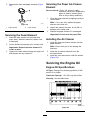
Servicing the Engine Oil . . . . . . . . . . . . . . . . . . . . . . . . . . . . . . . . . . . . 34
Servicing the Spark Plug . . . . . . . . . . . . . . . . . . . . . . . . . . . . . . . . . . . 37
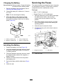
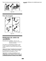
Cleaning the Blower Housing . . . . . . . . . . . . . . . . . . . . . . . . . . . . 37
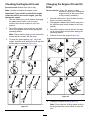
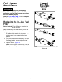
Fuel System Maintenance . . . . . . . . . . . . . . . . . . . . . . . . . . . . . . . . . . . 38
Replacing the In-Line Fuel Filter . . . . . . . . . . . . . . . . . . . . . . . 38
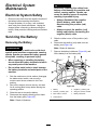
Electrical System Maintenance . . . . . . . . . . . . . . . . . . . . . . . . . . . 39
Electrical System Safety . . . . . . . . . . . . . . . . . . . . . . . . . . . . . . . . . . . 39
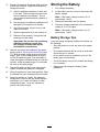
Servicing the Battery . . . . . . . . . . . . . . . . . . . . . . . . . . . . . . . . . . . . . . . . . 39
Servicing the Fuses . . . . . . . . . . . . . . . . . . . . . . . . . . . . . . . . . . . . . . . . . . 40
Drive System Maintenance . . . . . . . . . . . . . . . . . . . . . . . . . . . . . . . . . . 41
Checking the T ire Pressure . . . . . . . . . . . . . . . . . . . . . . . . . . . . . . . 41
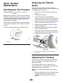
Releasing the Electric Brake . . . . . . . . . . . . . . . . . . . . . . . . . . . . . 41
Adjusting the T racking . . . . . . . . . . . . . . . . . . . . . . . . . . . . . . . . . . . . . . 41
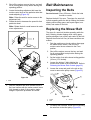
Belt Maintenance . . . . . . . . . . . . . . . . . . . . . . . . . . . . . . . . . . . . . . . . . . . . . . . . 42
Inspecting the Belts . . . . . . . . . . . . . . . . . . . . . . . . . . . . . . . . . . . . . . . . . . 42
Replacing the Mower Belt . . . . . . . . . . . . . . . . . . . . . . . . . . . . . . . . . 42
Mower Maintenance . . . . . . . . . . . . . . . . . . . . . . . . . . . . . . . . . . . . . . . . . . . . . 44
Blade Safety . . . . . . . . . . . . . . . . . . . . . . . . . . . . . . . . . . . . . . . . . . . . . . . . . . . . . 44
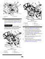
Servicing the Cutting Blades . . . . . . . . . . . . . . . . . . . . . . . . . . . . . 44
Leveling the Mower Deck . . . . . . . . . . . . . . . . . . . . . . . . . . . . . . . . . . 46
Removing the Mower Deck . . . . . . . . . . . . . . . . . . . . . . . . . . . . . . . 49
Installing the Mower Deck . . . . . . . . . . . . . . . . . . . . . . . . . . . . . . . . . 50
Replacing the Grass Deector . . . . . . . . . . . . . . . . . . . . . . . . . . 50
Cleaning . . . . . . . . . . . . . . . . . . . . . . . . . . . . . . . . . . . . . . . . . . . . . . . . . . . . . . . . . . . . . . 51
W ashing the Underside of the Mower
Deck .............................................................. 51
Disposing of W aste . . . . . . . . . . . . . . . . . . . . . . . . . . . . . . . . . . . . . . . . . . . 52
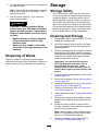
Storage . . . . . . . . . . . . . . . . . . . . . . . . . . . . . . . . . . . . . . . . . . . . . . . . . . . . . . . . . . . . . . . . . . . 52
Storage Safety . . . . . . . . . . . . . . . . . . . . . . . . . . . . . . . . . . . . . . . . . . . . . . . . . . 52
Cleaning and Storage . . . . . . . . . . . . . . . . . . . . . . . . . . . . . . . . . . . . . . . 52
Storing the Battery . . . . . . . . . . . . . . . . . . . . . . . . . . . . . . . . . . . . . . . . . . . . 53
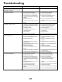
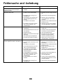
T roubleshooting . . . . . . . . . . . . . . . . . . . . . . . . . . . . . . . . . . . . . . . . . . . . . . . . . . . . . . 54
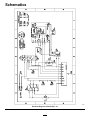
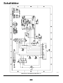
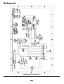
Schematics . . . . . . . . . . . . . . . . . . . . . . . . . . . . . . . . . . . . . . . . . . . . . . . . . . . . . . . . . . . . . 56
3

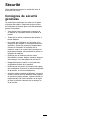
Safety
This machine has been designed in accordance with
EN ISO 5395.
General Safety
This product is capable of amputating hands and
feet and of throwing objects. Always follow all safety
instructions to avoid serious personal injury or death.
•Read and understand the contents of this
Operator ’ s Manual before starting the engine.
•Keep bystanders and children away .
•Do not allow children or untrained people to
operate or service the machine. Allow only people
who are responsible, trained, familiar with the
instructions, and physically capable to operate or
service the machine.
•Do not operate the machine near drop-of fs,
ditches, embankments, water , or other hazards, or
on slopes greater than 15°.
•Do not put your hands or feet near moving
components of the machine.
•Do not operate the machine without all guards,
safety switches, and other safety protective
devices in place and functioning properly .
•Shut of f the engine, remove the key , and wait
for all moving parts to stop before leaving the
operator ’ s position. Allow the machine to cool
before servicing, adjusting, fueling, cleaning, or
storing it.
4

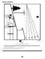
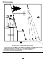
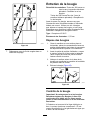
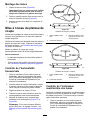
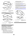
Slope Indicator
g01 1841
Figure 3
Y ou may copy this page for personal use.
1. The maximum slope you can operate the machine on is 15 degrees . Use the slope chart to determine the degree of slope of
hills before operating. Do not operate this machine on a slope greater than 15 degrees. Fold along the appropriate line
to match the recommended slope.
2. Align this edge with a vertical surface, a tree, building, fence pole, etc.
3. Example of how to compare slope with folded edge
5

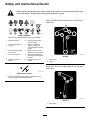
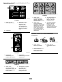
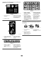
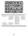
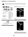
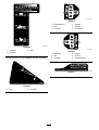
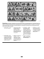
Safety and Instructional Decals
Safety decals and instructions are easily visible to the operator and are located near any area
of potential danger . Replace any decal that is damaged or missing.
decalbatterysymbols
Battery Symbols
Some or all of these symbols are on your battery .
1. Explosion hazard 6. Keep bystanders away
from the battery .
2. No re, open ame, or
smoking
7. W ear eye protection;
explosive gases can
cause blindness and other
injuries.
3. Caustic liquid/chemical
burn hazard
8. Battery acid can cause
blindness or severe burns.
4. W ear eye protection. 9. Flush eyes immediately
with water and get medical
help fast.
5. Read the Operator's
Manual .
10. Contains lead; do not
discard
decaloemmarkt
Manufacturer's Mark
1. This mark indicates that the blade is identied as a part
from the original machine manufacturer .
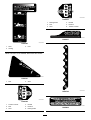
Decal 99-3943 is for models with 127 cm (50 inch)
decks only .
decal99-3943
99-3943
1. Belt routing
2. Engine
Decal 105-7015 is for models with 107 cm (42 inch)
decks only .
decal105-7015
105-7015
1. Belt routing
6

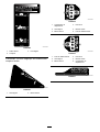
Decal 1 12-9840 is for models with 127 cm (50 inch)
decks only .
decal1 12-9840
1 12-9840
1. Read the Operator's
Manual .
3. Remove the ignition key
and read the instructions
before servicing or
performing maintenance.
2. Height of cut
decal121-2989b
121-2989
1. Bypass lever position for
pushing the machine
2. Bypass lever position for
operating the machine
decal130-0731
130-0731
1. W arning—thrown object
hazard; keep the deector
shield in place.
2. Cutting hazard of hand or
foot, mower blade—keep
away from moving parts.
decal132-0872
132-0872
1. Thrown object
hazard—keep bystanders
away from the machine.
3. Severing hazard of hand
or foot—keep away from
moving parts.
2. Thrown object hazard,
raised deector—do not
operate the machine with
an open deck; use a
bagger or a deector .
4. Entanglement
hazard—keep away
from moving parts; keep
all guards and shields in
place.
Decal 138-6074 is molded into the fuel tank.
decal138-2456
138-6074
1. Read the Operator ’ s
Manual .
3. Do not overll the fuel
tank.
2. Park the machine on a
level surface when lling
the fuel tank.
7

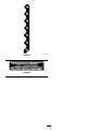
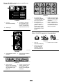
decal139-2388
139-2388
1. Slow
3. Fast
2. Hauling
Decal 139-2391 is for models without an hour meter .
decal139-2391
139-2391
1. Fast
2. Slow
decal139-2394
139-2394
1. T raction controls 4. Neutral
2. Fast 5. Reverse
3. Slow
6. Parking brake
decal139-2395
139-2395
1. Parking brake 4. Neutral
2. Fast 5. Reverse
3. Slow
6. T raction controls
decal139-2397
139-2397
decal140-2748
140-2748
decal142-5864
142-5864
8

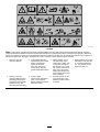
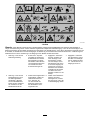
decal132-0869
132-0869
Note: This machine complies with the industry standard stability test in the static lateral and longitudinal tests with the maximum
recommended slope indicated on the decal. Review the instructions for operating the machine on slopes in the Operator ’ s Manual as
well as the conditions in which you would operate the machine to determine whether you can operate the machine in the conditions on
that day and at that site. Changes in the terrain can result in a change in slope operation for the machine.
1. W arning—read the
Operator's Manual .
3. Cutting/dismemberment
hazard of the hand, mower
blade; entanglement
hazard of the hand,
belt—stay away from
moving parts; keep all
guards and shields in place.
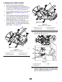
5. T ipping hazard—do not
use dual ramps when
loading onto a trailer; use
1 ramp wide enough for
the machine; use a ramp
with a slope less than 15°;
back up the ramp when
loading the machine and
drive forward of f the ramp
when unloading.
7. T ipping hazard—do not use
the machine near drop-of fs
or on slopes greater than
15°; only operate across
slopes less than 15°.
2. W arning—read the
Operator's Manual before
performing maintenance;
engage the parking brake,
remove the key , and
disconnect the spark plug.
4. Thrown object
hazard—keep bystanders
away; pick up debris
before operating; keep the
deector in place.
6. Runover hazard—do not
carry passengers; look
behind you when mowing
in reverse.
9

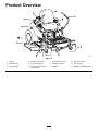
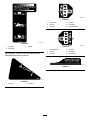
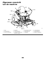
Product Overview
g367815
Figure 4
1. Engine 4. Motion-control levers
7. Smart Speed ™lever
10. Rear drive wheel
2. Operator seat
5. Front caster wheel
8. Height-of-cut lever 1 1. Control panel
3. Fuel-tank cap
6. Deck-lift pedal (certain
models only)
9. Deector
12. MyRide ™adjustment lever
10

Controls
Become familiar with all the controls before you start
the engine and operate the machine.
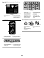
Control Panel
g293303
Figure 5
1. Throttle control 3. Blade-control switch
(power takeof f)
2. Choke control
4. Key switch
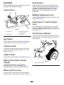
Key Switch
The key switch, used to start and shut of f the engine,
has 3 positions: O FF , R UN , and S TART (Figure 5 ).
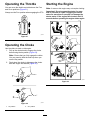
Throttle Control
The throttle controls the engine speed, and it has a
continuous-variable setting from the S LOW to F AST
position ( Figure 5 ).
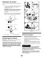
Choke Control
Use the choke control to start a cold engine ( Figure 5 ).
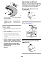
Blade-Control Switch (Power
T akeoff)
The blade-control switch, represented by a
power-takeof f (PT O) symbol, engages and
disengages power to the mower blades ( Figure 5 ).
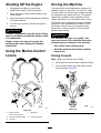
Motion-Control Levers
Use the motion-control levers to drive the machine
forward, reverse, and turn either direction ( Figure 4 ).
Park Position
Move the motion-control levers outward from the
center to the P ARK position when exiting the machine
to engage the electric brake ( Figure 24 ). Always
position the motion-control levers into the P ARK
position when you stop the machine or leave it
unattended.
MyRide® Adjustment Lever
Use the MyRide® adjustment lever to adjust the seat
suspension ( Figure 4 ).
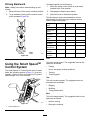
Smart Speed ™Control System
Lever
The Smart Speed ™Control-System lever , located
below the operating position, gives you a choice to
drive the machine at 3 speed ranges— trim, tow , and
mow ( Figure 27 ).
Fuel-Presence W indow
Y ou can use the fuel window , located on the left side
of the machine, to verify the presence of fuel in the
tank ( Figure 6 ).
g292100
Figure 6
1. Fuel-presence window
1 1

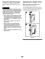
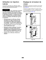
Height-of-Cut Lever
Use the height-of-cut lever to lower and raise the deck
from the seated position. Moving the lever up (toward
you) raises the deck from the ground and moving the
lever down (away from you) lowers the deck toward
the ground. Adjust the height-of-cut only while the
machine is not moving ( Figure 28 ).
Foot Pedal Deck-Lift System
Certain Models Only
The foot pedal deck-lift system allows you to lower and
raise the deck from the seated position. Y ou can use
the foot pedal to lift the deck briey to avoid obstacles
or assist in adjusting the height of cut ( Figure 4 ).
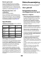
Specications
Specications and design are subject to change
without notice.
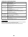
42in Mower Deck 50in Mower Deck
Cutting width 107 cm (42 inches) 127 cm (50 inches)
Width with
deector down
135 cm (53 inches) 155 cm (61 inches)
Width with
deector raised
123 cm (48.5
inches)
130 cm (51 inches)
Length
185 cm (73 inches) 186 cm (73 inches)
Height
1 12 cm (44 inches) 109 cm (43 inches)
W eight
332 kg (731 lb) 353 kg (779 lb)
Attachments/Accessories
A selection of T oro approved attachments and
accessories is available for use with the machine
to enhance and expand its capabilities. Contact
your Authorized Service Dealer or authorized T oro
distributor or go to www .T oro.com for a list of all
approved attachments and accessories.
T o ensure optimum performance and continued safety
certication of the machine, use only genuine T oro
replacement parts and accessories. Replacement
parts and accessories made by other manufacturers
could be dangerous, and such use could void the
product warranty .
Operation
Note: Determine the left and right sides of the
machine from the normal operating position.
Before Operation
Before Operation Safety
General Safety
•Do not allow children or untrained people to
operate or service the machine. Local regulations
may restrict the age of the operator . The owner
is responsible for training all operators and
mechanics.
•Inspect the area where you will use the machine,
and remove all objects that could interfere with
the operation of the machine or that the machine
could throw .
•Become familiar with the safe operation of the
equipment, operator controls, and safety signs.
•Check that operator-presence controls, safety
switches, and guards are attached and working
properly . Do not operate the machine unless they
are functioning properly .
•Shut of f the engine, remove the key , and wait
for all moving parts to stop before leaving the
operator ’ s position. Allow the machine to cool
before servicing, adjusting, fueling, cleaning, or
storing it.
•Before mowing, inspect the machine to ensure
that the cutting assemblies are working properly .
•Evaluate the terrain to determine the appropriate
equipment and any attachments or accessories
required to operate the machine properly and
safely .
•W ear appropriate clothing, including eye
protection; long pants; substantial, slip-resistant
footwear; and hearing protection. T ie back long
hair and do not wear loose clothing or loose
jewelry .
•Do not carry passengers on the machine.
•Keep bystanders and pets away from the machine
during operation. Shut of f the machine and
attachment(s) if anyone enters the area.
•Do not operate the machine unless all guards and
safety devices, such as the deectors and the
entire grass catcher , are in place and functioning
properly . Replace worn or deteriorated parts when
necessary .
12

Fuel Safety
•Fuel is extremely ammable and highly explosive.
A re or explosion from fuel can burn you and
others and can damage property .
– T o prevent a static charge from igniting the
fuel, remove the machine from the truck or
trailer and refuel it on the ground, away from
all vehicles. If this is not possible, place a
portable fuel container on the ground, away
from all vehicles, and ll it; then refuel the
machine from the fuel container rather than
from a fuel-dispenser nozzle.
– Fill the fuel tank outdoors on level ground, in
an open area, and when the engine is cold.
Wipe up any fuel that spills.
– Do not handle fuel when smoking or around an
open ame or sparks.
– Do not remove the fuel cap or add fuel to the
tank while the engine is running or hot.
– If you spill fuel, do not attempt to start the
engine. A void creating a source of ignition until
the fuel vapors have dissipated.
– Store fuel in an approved container and keep
it out of the reach of children.
•Fuel is harmful or fatal if swallowed. Long-term
exposure to vapors can cause serious injury and
illness.
– A void prolonged breathing of vapors.
– Keep your hands and face away from the
nozzle and the fuel-tank opening.
– Keep fuel away from your eyes and skin.
•Do not store the machine or fuel container where
there is an open ame, spark, or pilot light, such
as on a water heater or on other appliances.
•Do not operate the machine without the entire
exhaust system in place and in proper working
condition.
•Keep the fuel-dispenser nozzle in contact with
the rim of the fuel tank or container opening at
all times until fueling is complete. Do not use a
nozzle lock-open device.
•If you spill fuel on your clothing, change your
clothing immediately .
•Do not overll the fuel tank. Replace the fuel cap
and tighten it securely .
•Clean grass and debris from the cutting unit,
muf er , drives, grass catcher , and engine
compartment to help prevent res. Clean up oil or
fuel spills.
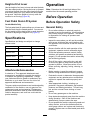
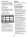
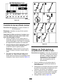
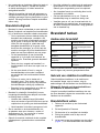
Adding Fuel
Recommended Fuel
T ype Unleaded gasoline
Minimum octane rating
87 (US) or 91 (research
octane; outside the US)
Ethanol
No more than 10% by volume
Methanol None
MTBE (methyl tertiary butyl
ether)
Less than 15% by volume
Oil Do not add to the fuel
Use only clean, fresh (no more than 30 days old), fuel
from a reputable source.
Using Stabilizer/Conditioner
Use fuel stabilizer/conditioner in the machine to keep
the fuel fresh longer when used as directed by the
fuel-stabilizer manufacturer .
Important: Do not use fuel additives containing
methanol or ethanol.
Add the amount of fuel stabilizer/conditioner to fresh
fuel as directed by the fuel-stabilizer manufacturer .
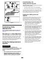
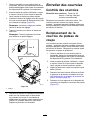
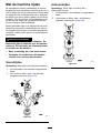
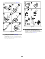
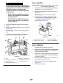
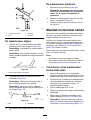
Filling the Fuel T ank
1. Park the machine on a level surface.
2. Move the motion-control levers outward to the
PARK position.
3. Shut of f the engine and remove the key .
4. Clean around the fuel-tank cap.
5. Fill the fuel tank to the bottom of the ller neck
(Figure 7 ). Do not ll the fuel tank completely
full.
13

g293796
Figure 7
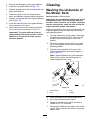
Performing Daily
Maintenance
Before starting the machine each day , perform the
Each Use/Daily procedures listed in Maintenance
( page 30 ) .
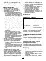
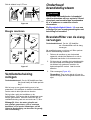
Breaking in a New Machine
New engines take time to develop full power . Mower
decks and drive systems have higher friction when
new , placing additional load on the engine. Allow
40 to 50 hours of break-in time for new machines to
develop full power and best performance.
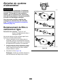
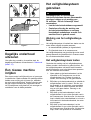
Using the Safety-Interlock
System
W ARNING
If the safety-interlock switches are
disconnected or damaged, the machine could
operate unexpectedly , causing personal
injury .
• Do not tamper with the interlock switches.
• Check the operation of the interlock
switches daily and replace any damaged
switches before operating the machine.
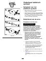
Understanding the
Safety-Interlock System
The safety-interlock system is designed to prevent the
engine from starting unless:
•The blade-control switch (PT O) is disengaged.
•The motion-control levers are in the P ARK position.
The safety-interlock system also is designed to shut
of f the engine whenever the control levers are out of
the P ARK position and you rise from the seat.
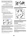
T esting the Safety-Interlock
System
T est the safety-interlock system before you use the
machine each time. If the safety system does not
operate as described below , have an Authorized
Service Dealer repair the safety system immediately .
1. Sit on the seat, move the motion-control levers
in the P ARK position, and move the blade-control
switch to the O Nposition. T ry starting the
engine; the engine should not crank.
2. Sit on the seat and move the blade-control switch
to the O FF position. Move either motion-control
lever to the center , unlocked position. T ry
starting the engine; the engine should not crank.
Repeat with the other motion-control lever .
3. Sit on the seat, move the blade-control switch
to the O FF position, and lock the motion-control
levers in the P ARK position. Start the engine.
While the engine is running, engage the
blade-control switch, and rise slightly from the
seat; the engine should shut of f.
4. Sit on the seat, move the blade-control switch
to the O FF position, and lock the motion-control
levers in the P ARK position. Start the engine.
While the engine is running, move the
motion-control levers to the center , unlocked
position and rise slightly from the seat; the
engine should shut of f.
14

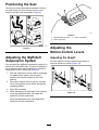
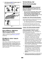
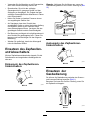
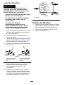
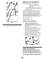
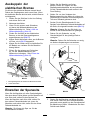
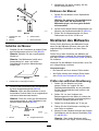
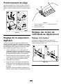
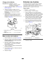
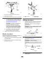
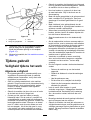
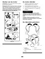
Positioning the Seat
The seat can move forward and backward. Position
the seat where you have the best control of the
machine and are most comfortable ( Figure 8 ).
g027632
Figure 8
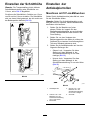
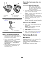
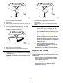
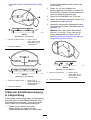
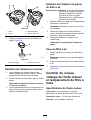
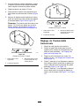
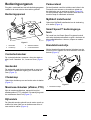
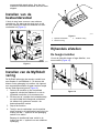
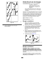
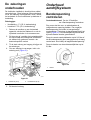
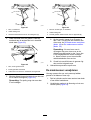
Adjusting the MyRide®
Suspension System
Y ou can adjust the MyRide® suspension system for a
smooth and comfortable ride. The slots for adjusting
the suspension have detent positions for reference,
ranging from a soft to a rm ride ( Figure 9 ).
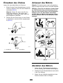
1. Park the machine on a level surface, disengage
the blade-control switch, and move the
motion-control levers outward to the P ARK
position.
2. Shut of f the engine, remove the key , and wait
for all moving parts to stop before leaving the
operating position.
3. Step of f the machine.
4. While standing on the right side of the machine,
move the adjustment lever left toward the –
symbol for a softer suspension.
Move the adjustment lever right toward the +
symbol for a rmer suspension.
g292102
Figure 9
1. MyRide adjustment lever 3. Firmer suspension
2. Softer suspension
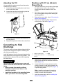
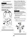
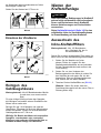
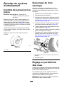
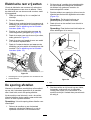
Adjusting the
Motion-Control Levers
Adjusting the Height
Y ou can adjust the motion-control levers higher or
lower for maximum comfort ( Figure 10 ).
g333847
Figure 10
15

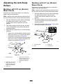
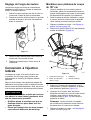
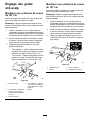
Adjusting the T ilt
Y ou can adjust the motion-control levers forward or
rearward for your comfort.
1. Loosen the upper bolt holding the control lever
to the control-arm shaft.
2. Loosen the lower bolt just enough to pivot the
control lever forward or rearward.
g333846
Figure 1 1
3. T ighten both bolts to secure the control lever in
the new position.
4. Repeat the adjustment for the other control lever .
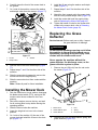
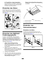
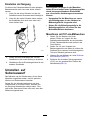
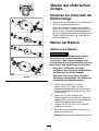
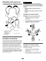
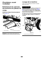
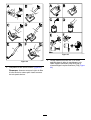
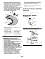
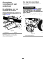
Converting to Side
Discharge
The mower deck and mower blades shipped with the
machine were designed for optimum mulching and
side-discharge performance.
Install the fasteners from the loose parts bag into the
empty holes after removing the recyling baf es.. This
ensures that no holes are left open when operating
the mower deck.
W ARNING
Open holes in the machine expose you and
others to thrown debris that can cause severe
injury .
• Never operate the machine without
hardware mounted in all holes in the
machine housing.
• Install the hardware in the mounting holes
when you remove the mulching bafe.
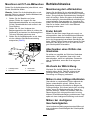
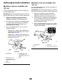
Machines with 107 cm (42-inch)
Mower Decks
1. Park the machine on a level surface, disengage
the blade-control switch, and move the
motion-control levers outward to the P ARK
position.
2. Shut of f the engine, remove the key , and wait
for all moving parts to stop before leaving the
operating position.
3. Remove the mower deck; refer to Removing the
Mower Deck ( page 49 ) .
4. Remove the 2 locknuts (5/16 inch) from the
welded posts of the baf e ( Figure 12 ).
g296990
Figure 12
1. Locknut—5/16 inch (4) 3. Baf e
2. Carriage bolt—5/16 x 3/4
inch (2)
4. W elded post (2)
5. Remove the 2 carriage bolts and 2 locknuts
securing the baf e to the deck and remove the
baf e ( Figure 12 )
6. Locate the 2 bolts in loose parts and use the
existing locknuts to install these fasteners into
the holes used for the welded posts ( Figure 12 )
to prevent ying debris.
Note: Install the bolt upward, through the
underside of the deck and use an existing
locknut to secure from the topside.
7. Install the mower deck; refer to Installing the
Mower Deck ( page 50 ) .
16

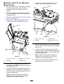
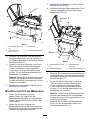
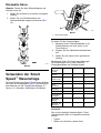
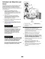
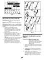
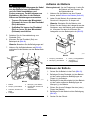
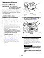
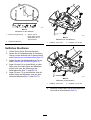
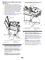
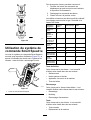
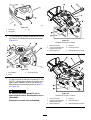
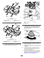
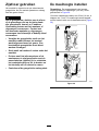
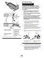
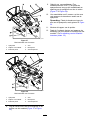
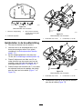
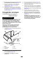
Machines with 127 cm (50-inch)
Mower Decks
1. Park the machine on a level surface, disengage
the blade-control switch, and move the
motion-control levers outward to the P ARK
position.
2. Shut of f the engine, remove the key , and wait
for all moving parts to stop before leaving the
operating position.
3. Remove the mower deck; refer to Removing the
Mower Deck ( page 49 ) .
4. Remove the 3 locknuts (5/16 inch) from the
welded posts of the right baf e ( Figure 13 ).
g297022
Figure 13
1. Locknut—5/16 inch (4) 3. Carriage bolt—5/16 x 3/4
inch
2. Right baf e 4. W elded post (3)
5. Remove the 2 carriage bolts and 2 locknuts
securing the right baf e to the deck and remove
the baf e ( Figure 13 ).
6. Locate the 3 bolts in loose parts and use the
existing locknuts and install these fasteners into
the holes used for the welded posts ( Figure 13 )
to prevent ying debris.
Note: Install the bolt upward, through the
underside of the deck and use an existing
locknut to secure from the topside.
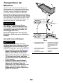
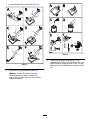
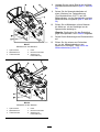
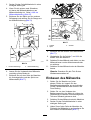
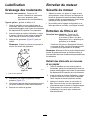
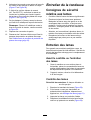
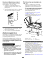
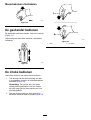
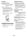
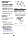
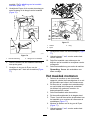
7. Remove the 2 locknuts (5/16 inch) from the
welded posts of the left baf e ( Figure 14 ).
g297021
Figure 14
1. Locknut—5/16 inch (3) 3. W elded post (2)
2. Left baf e 4. Carriage bolt—5/16 x 3/4
inch
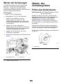
8. Remove the carriage bolt and locknut securing
the left baf e to the deck and remove the baf e
(Figure 14 ).
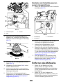
9. Locate the 2 bolts in loose parts and use the
existing locknuts and install these fasteners into
the holes shown in Figure 14 on the mower deck
to prevent ying debris.
Note: Install the bolt upward, through the
underside of the deck and use an existing
locknut to secure from the topside.
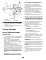
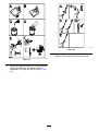
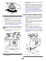
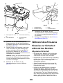
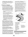
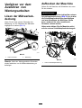
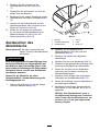
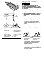
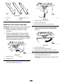
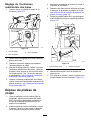
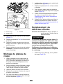
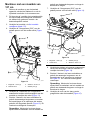
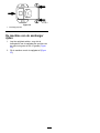
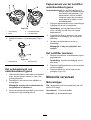
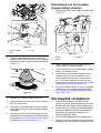
10. Remove the nut from the grass deector rod
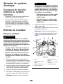
under the mower deck ( Figure 15 ).
17

g297046
Figure 15
1. Grass deector
3. Nut
2. Grass deector rod 4. Cutof f baf e
1 1. Use the nut to install the cutof f baf e to the grass
deector rod, using the outer hole in the baf e
(Figure 15 ).
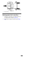
12. Install the mower deck; refer to Installing the
Mower Deck ( page 50 ) .
During Operation
During Operation Safety
General Safety
•The owner/operator can prevent and is responsible
for accidents that may cause personal injury or
property damage.
•Use your full attention while operating the
machine. Do not engage in any activity that
causes distractions; otherwise, injury or property
damage may occur .
•Do not operate the machine while ill, tired, or
under the inuence of alcohol or drugs.
•Contacting the blade can result in serious personal
injury . Shut of f the engine, remove the key , and
wait for all moving parts to stop before leaving the
operating position. When you turn the key to the
OFF position, the engine should shut of f and the
blade should stop. If not, stop using your machine
immediately and contact an Authorized Service
Dealer .
•Operate the machine only in good visibility and
appropriate weather conditions. Do not operate
the machine when there is the risk of lightning.
•Keep your hands and feet away from the cutting
units. Keep clear of the discharge opening.
•Do not mow with the discharge deector
raised, removed, or altered unless there is a
grass-collection system or mulch kit in place and
working properly .
•Do not mow in reverse unless it is absolutely
necessary . Always look down and behind you
before moving the machine in reverse.
•Use extreme care when approaching blind
corners, shrubs, trees, or other objects that may
block your view .
•Stop the blades whenever you are not mowing.
•If the machine strikes an object or starts to vibrate,
immediately shut of f the engine, remove the key
(if equipped), and wait for all moving parts to stop
before examining the machine for damage. Make
all necessary repairs before resuming operation.
•Slow down and use caution when making turns
and crossing roads and sidewalks with the
machine. Always yield the right-of-way .
•Before you leave the operating position, do the
following:
– Park the machine on a level surface.
– Disengage the power takeof f and lower the
attachments.
– Engage the parking brake.
– Shut of f the engine and remove the key .
– W ait for all moving parts to stop.
•Operate the engine only in well-ventilated areas.
Exhaust gases contain carbon monoxide, which
is lethal if inhaled.
•Never leave a running machine unattended.
•Attach towed equipment to the machine only at
the hitch point.
•Do not operate the machine unless all guards and
safety devices, such as the deectors and the
entire grass catcher , are in place and functioning
properly . Replace worn or deteriorated parts when
necessary .
•Use only accessories and attachments approved
by T oro.
•This machine produces sound levels in excess
of 85 dBA at the operator ’ s ear and can cause
hearing loss through extended periods of
exposure.
18
La page charge ...
La page charge ...
La page charge ...
La page charge ...
La page charge ...
La page charge ...
La page charge ...
La page charge ...
La page charge ...
La page charge ...
La page charge ...
La page charge ...
La page charge ...
La page charge ...
La page charge ...
La page charge ...
La page charge ...
La page charge ...
La page charge ...
La page charge ...
La page charge ...
La page charge ...
La page charge ...
La page charge ...
La page charge ...
La page charge ...
La page charge ...
La page charge ...
La page charge ...
La page charge ...
La page charge ...
La page charge ...
La page charge ...
La page charge ...
La page charge ...
La page charge ...
La page charge ...
La page charge ...
La page charge ...
La page charge ...
La page charge ...
La page charge ...
La page charge ...
La page charge ...
La page charge ...
La page charge ...
La page charge ...
La page charge ...
La page charge ...
La page charge ...
La page charge ...
La page charge ...
La page charge ...
La page charge ...
La page charge ...
La page charge ...
La page charge ...
La page charge ...
La page charge ...
La page charge ...
La page charge ...
La page charge ...
La page charge ...
La page charge ...
La page charge ...
La page charge ...
La page charge ...
La page charge ...
La page charge ...
La page charge ...
La page charge ...
La page charge ...
La page charge ...
La page charge ...
La page charge ...
La page charge ...
La page charge ...
La page charge ...
La page charge ...
La page charge ...
La page charge ...
La page charge ...
La page charge ...
La page charge ...
La page charge ...
La page charge ...
La page charge ...
La page charge ...
La page charge ...
La page charge ...
La page charge ...
La page charge ...
La page charge ...
La page charge ...
La page charge ...
La page charge ...
La page charge ...
La page charge ...
La page charge ...
La page charge ...
La page charge ...
La page charge ...
La page charge ...
La page charge ...
La page charge ...
La page charge ...
La page charge ...
La page charge ...
La page charge ...
La page charge ...
La page charge ...
La page charge ...
La page charge ...
La page charge ...
La page charge ...
La page charge ...
La page charge ...
La page charge ...
La page charge ...
La page charge ...
La page charge ...
La page charge ...
La page charge ...
La page charge ...
La page charge ...
La page charge ...
La page charge ...
La page charge ...
La page charge ...
La page charge ...
La page charge ...
La page charge ...
La page charge ...
La page charge ...
La page charge ...
La page charge ...
La page charge ...
La page charge ...
La page charge ...
La page charge ...
La page charge ...
La page charge ...
La page charge ...
La page charge ...
La page charge ...
La page charge ...
La page charge ...
La page charge ...
La page charge ...
La page charge ...
La page charge ...
La page charge ...
La page charge ...
La page charge ...
La page charge ...
La page charge ...
La page charge ...
La page charge ...
La page charge ...
La page charge ...
La page charge ...
La page charge ...
La page charge ...
La page charge ...
La page charge ...
La page charge ...
La page charge ...
La page charge ...
La page charge ...
La page charge ...
La page charge ...
La page charge ...
La page charge ...
La page charge ...
La page charge ...
La page charge ...
La page charge ...
La page charge ...
La page charge ...
La page charge ...
La page charge ...
La page charge ...
La page charge ...
La page charge ...
La page charge ...
La page charge ...
La page charge ...
La page charge ...
La page charge ...
La page charge ...
La page charge ...
La page charge ...
La page charge ...
La page charge ...
La page charge ...
La page charge ...
La page charge ...
La page charge ...
La page charge ...
La page charge ...
La page charge ...
La page charge ...
La page charge ...
La page charge ...
La page charge ...
La page charge ...
La page charge ...
La page charge ...
La page charge ...
La page charge ...
La page charge ...
La page charge ...
La page charge ...
La page charge ...
La page charge ...
La page charge ...
La page charge ...
La page charge ...
La page charge ...
La page charge ...
La page charge ...
La page charge ...
La page charge ...
La page charge ...
La page charge ...
La page charge ...
La page charge ...
La page charge ...
La page charge ...
La page charge ...
La page charge ...
La page charge ...
-
 1
1
-
 2
2
-
 3
3
-
 4
4
-
 5
5
-
 6
6
-
 7
7
-
 8
8
-
 9
9
-
 10
10
-
 11
11
-
 12
12
-
 13
13
-
 14
14
-
 15
15
-
 16
16
-
 17
17
-
 18
18
-
 19
19
-
 20
20
-
 21
21
-
 22
22
-
 23
23
-
 24
24
-
 25
25
-
 26
26
-
 27
27
-
 28
28
-
 29
29
-
 30
30
-
 31
31
-
 32
32
-
 33
33
-
 34
34
-
 35
35
-
 36
36
-
 37
37
-
 38
38
-
 39
39
-
 40
40
-
 41
41
-
 42
42
-
 43
43
-
 44
44
-
 45
45
-
 46
46
-
 47
47
-
 48
48
-
 49
49
-
 50
50
-
 51
51
-
 52
52
-
 53
53
-
 54
54
-
 55
55
-
 56
56
-
 57
57
-
 58
58
-
 59
59
-
 60
60
-
 61
61
-
 62
62
-
 63
63
-
 64
64
-
 65
65
-
 66
66
-
 67
67
-
 68
68
-
 69
69
-
 70
70
-
 71
71
-
 72
72
-
 73
73
-
 74
74
-
 75
75
-
 76
76
-
 77
77
-
 78
78
-
 79
79
-
 80
80
-
 81
81
-
 82
82
-
 83
83
-
 84
84
-
 85
85
-
 86
86
-
 87
87
-
 88
88
-
 89
89
-
 90
90
-
 91
91
-
 92
92
-
 93
93
-
 94
94
-
 95
95
-
 96
96
-
 97
97
-
 98
98
-
 99
99
-
 100
100
-
 101
101
-
 102
102
-
 103
103
-
 104
104
-
 105
105
-
 106
106
-
 107
107
-
 108
108
-
 109
109
-
 110
110
-
 111
111
-
 112
112
-
 113
113
-
 114
114
-
 115
115
-
 116
116
-
 117
117
-
 118
118
-
 119
119
-
 120
120
-
 121
121
-
 122
122
-
 123
123
-
 124
124
-
 125
125
-
 126
126
-
 127
127
-
 128
128
-
 129
129
-
 130
130
-
 131
131
-
 132
132
-
 133
133
-
 134
134
-
 135
135
-
 136
136
-
 137
137
-
 138
138
-
 139
139
-
 140
140
-
 141
141
-
 142
142
-
 143
143
-
 144
144
-
 145
145
-
 146
146
-
 147
147
-
 148
148
-
 149
149
-
 150
150
-
 151
151
-
 152
152
-
 153
153
-
 154
154
-
 155
155
-
 156
156
-
 157
157
-
 158
158
-
 159
159
-
 160
160
-
 161
161
-
 162
162
-
 163
163
-
 164
164
-
 165
165
-
 166
166
-
 167
167
-
 168
168
-
 169
169
-
 170
170
-
 171
171
-
 172
172
-
 173
173
-
 174
174
-
 175
175
-
 176
176
-
 177
177
-
 178
178
-
 179
179
-
 180
180
-
 181
181
-
 182
182
-
 183
183
-
 184
184
-
 185
185
-
 186
186
-
 187
187
-
 188
188
-
 189
189
-
 190
190
-
 191
191
-
 192
192
-
 193
193
-
 194
194
-
 195
195
-
 196
196
-
 197
197
-
 198
198
-
 199
199
-
 200
200
-
 201
201
-
 202
202
-
 203
203
-
 204
204
-
 205
205
-
 206
206
-
 207
207
-
 208
208
-
 209
209
-
 210
210
-
 211
211
-
 212
212
-
 213
213
-
 214
214
-
 215
215
-
 216
216
-
 217
217
-
 218
218
-
 219
219
-
 220
220
-
 221
221
-
 222
222
-
 223
223
-
 224
224
-
 225
225
-
 226
226
-
 227
227
-
 228
228
-
 229
229
-
 230
230
-
 231
231
-
 232
232
-
 233
233
-
 234
234
-
 235
235
-
 236
236
-
 237
237
-
 238
238
-
 239
239
-
 240
240
-
 241
241
-
 242
242
-
 243
243
-
 244
244
-
 245
245
-
 246
246
-
 247
247
-
 248
248
-
 249
249
-
 250
250
-
 251
251
-
 252
252


Toro 127 cm TimeCutter MX 5075T Zero Turn Mower 74695 Manuel utilisateur
- Catégorie
- Tondeuses à gazon
- Taper
- Manuel utilisateur
- Ce manuel convient également à
dans d''autres langues
Documents connexes
-
Toro TimeCutter MX 4275T Riding Mower Manuel utilisateur
-
Toro TimeCutter Max 50in Zero Turn Riding Mower Manuel utilisateur
-
Toro Titan X4850 Riding Mower Manuel utilisateur
-
Toro Titan ZXM5475 Zero Turn Riding Mower Manuel utilisateur
-
Toro TimeCutter ZS 4200S Riding Mower Manuel utilisateur
-
Toro TimeCutter ZS 4200T Riding Mower Manuel utilisateur
-
Toro 132cm Z Master 4000 Series Riding Mower Manuel utilisateur
-
-
-
Toro TimeCutter 42in Riding Mower Manuel utilisateur