
Wattstopper
®
Occupancy and Light Level Sensor for Indoor/Outdoor Use
Line Voltage • Fixture Mount
Installation Instructions • Instructions d’Installation • Instrucciones de Instalación
No: 24044 – 02/18 rev. 1
Catalog Numbers • Les Numéros de Catalogue • Números de Catálogo: FS-355
Country of Origin: Made in China • Pays d’origine: Fabriqué en Chine • País de origen: Hecho en China
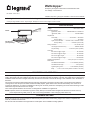
SPECIFICATIONS
Voltage ......................................................... 120-277VAC, 60Hz
Load Requirements
@120VAC, 60Hz ................... 0-800W ballast or incandescent
@277VAC, 60Hz .......................................... 0-1200W ballast
Adjustments
Time Delay .....................................30 seconds — 30 minutes
Factory Setting ...............................................15 minutes
Light Level, Hold OFF ....... minimum <10fc, maximum >120fc
Factory Setting .............................maximum (never hold)
Wiring Terminals .......................................................Hot, neutral, load
Use Copper Conductor Only .........................18AWG-14AWG
Torque Rating ................................4.428 inch-pound. (0.5Nm)
Coverage
FS-L2W Lens @ 8’ height ....................................48’ diameter
FS-L3W Lens @ 20’ height ..................................40’ diameter
FS-L6 Lens @ 8’ height........................................60’ diameter
FS-L7W Lens @ 40’ height ................................ 100’ diameter
Operating Temperature ........................-40°F (-40°C) to 131°F (55°C)
Dimensions
Threaded Neck Diameter .................1.14” diameter (28.8mm)
Threaded Neck Length ...................................... 0.38” (9.6mm)
Tightening Ring outer .......................1.28” diameter (32.6mm)
Body ......... 1.38” x 2.35” x 0.88” (35mm x 59.5mm x 22.7mm)
DESCRIPTION AND OPERATION
The FS-355 occupancy sensor turns lighting ON and OFF based on occupancy and ambient light levels. The light level feature (can be
used to keep lights from turning ON and turn them OFF if the ambient light level is sufficient. This slim, low-profile sensor is designed for
installation inside the bottom of a light fixture body. The PIR lens connects to the FS-355 through a 11/8” diameter hole in the bottom of
the fixture.
The sensors use passive infrared (PIR) sensing technology that reacts to changes in infrared energy (moving body heat) within the
coverage area. Once the space is vacant and the time delay elapses, lights will turn OFF. Sensors must directly “see” motion of an
occupant to detect them, so careful consideration must be given to sensor placement. Avoid placing the sensor where shelving or other
obstructions may block the sensor’s line of sight.
The FS-355 operates between 120-277VAC. It is designed for installation in a light fixture.
NOTE: Important, there is an initial warm-up period: It may take up to a minute before the lights turn ON due to a sensor warm-up
period required during initial power-up. This occurs during installation or after a lengthy power failure only.
COVERAGE PATTERN
Density and range of the coverage pattern is determined by the type of lens and mounting height. The FS-355 is compatible with
multi-cell, multi-tier Fresnel lenses.
See the FS-LxW Lens Module Coverage Guide for a description of the available coverage patterns.
FS-355
FS-LxW Lens
(sold separately)

2
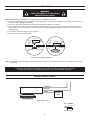
INSTALLATION
NOTE: OPEN DEVICE for installation in a Listed Enclosure per Installation Instructions.
1. Determine an appropriate mounting location inside the light fixture. Allow a minimum distance of 1.3” (33mm) from the center of
the sensor collar to the edge of the fixture.
2. Use a 11/8” (29mm) bit to drill a hole through the sheet metal in the bottom of the fixture.
3. From the inside of the fixture, insert the FS-355 lens pipe through the hole in the bottom of the fixture. Install the sensor face
down, parallel to the mounting surface. Hand tighten the Lens securely against the outside of the fixture. If necessary, use the
Tightening Ring.
4. Connect load and supply wires as shown in Figure 2.
5. Restore power from the circuit breaker.
Fig 1: FS-355 mounting in light xture
FS-355
Inside
Fixture
Wall
Outside
Fixture Wall
FS-355
Lens Assembly
Inside
Fixture
Wall
Outside
Fixture Wall
Tightening
Ring
Tightening
Ring
WIRING A SINGLE SENSOR
Load
Ballast
Load
Line/Hot
Neutral
Fig 2: FS-355 wiring
Strip Gauge
1/2"
12.7mm
#14 — #18 AWG
Cu Wire Only
NOTE: The Outside Fixture Wall thickness should be between 0.032” and 0.10” (0.82mm and 2.54mm) for optimal sensor mounting
and security.
Outdoor Use at the Sensor Collar part only when (Sensor Collar part exposed and) installed
at the specific location per Installation Instructions with a Listed Outdoor Enclosure.
WARNING:
TURN THE POWER OFF AT THE CIRCUIT
BREAKER BEFORE WIRING.

3
LIGHT LEVEL FEATURE
The Light Level feature holds OFF and turns OFF lights when the space is occupied and adequate ambient light exists. When the light
level drops below the set level it will turn the lights ON when the space is occupied. A sticker covers the photosensor and must be
removed before this feature will function. The factory setting is for maximum, meaning that even bright ambient light will not cause the
sensor to hold the lights OFF if it detects occupancy in the controlled area.
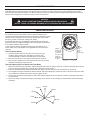
SENSOR ADJUSTMENT
The Light Level and Time Delay adjustment trimpots are located under the
lens assembly. (Remove the sticker to see the Light Level trimpot.) The
trimpots are accessed easily after the sensor is mounted in the fixture. Gently
unscrew the lens assembly. Do not remove the thumbscrew collar; it holds
the sensor in place on the fixture. Identify each trimpot.
Set the light level when the controlled light would normally be turned OFF
due to the presence of sufficient daylight or other electric light. (If this feature
is not needed, leave the sticker in place.
* At the maximum setting, the light level entering the photosensor must
exceed 120fc, which only happens in rare applications or when the lens is
removed.
Test Occupancy Sensor
1. If sticker has been removed, set Light Level to maximum (fully
clockwise, factory setting). Set Time Delay to minimum (fully
counterclockwise). Put the lens assembly back onto the sensor.
2. Move out of the sensor’s view. Lights turn OFF after 30 seconds.
3. Move into the controlled area. The red LED in the sensor lens should
illuminate and the lights should turn ON.
Test and Adjust Light Level Sensor and Time Delay
1. Remove the lens assembly and sticker. Adjust the light level and the time delay to minimum. Put the lens assembly back onto the
sensor. Leave the controlled area and let the sensor time out so lights are OFF.
2. Enter the controlled area and lights should remain OFF. Make sure your body does not cast a shadow on the sensor.
3. Turn the light level trimpot clockwise in small increments. After each adjustment, put the lens back on the sensor then move about
the controlled area. Wait 5-10 seconds to see if the lights turn ON.
4. Continue this procedure until the lights turn ON. At this setting the lights will not turn ON with occupancy if the light level is above
the current level.
5. Set the time delay to the desired setting. The time delay can be set from 30 seconds (fully counterclockwise) to 30 minutes (fully
clockwise).
CAUTION
DO NOT OVERTURN TRIMPOT WHEN ADJUSTING THE SENSOR.
DO NOT TOUCH THE SQUARE INFRARED DETECTORUNDER THE LENS ASSEMBLY.
20 min.
25 min.
10 min.
5 min.
30 min.
30 sec.
15 min.
A
ttention:
Remove label
to enable light
level feature.
The Light Level
adjustment
trimpot is under
the sticker.
Time Delay
Range:
30 sec. to
30 min.
15 min default

800.879.8585
www.legrand.us/wattstopper
No. 24044 – 02/18 rev. 1
© Copyright 2018 Legrand All Rights Reserved.
© Copyright 2018 Tous droits réservés Legrand.
© Copyright 2018 Legrand Todos los derechos reservados.
Wattstopper warranties its products to be free
of defects in materials and workmanship for a
period of five (5) years. There are no obligations
or liabilities on the part of Wattstopper for
consequential damages arising out of, or in
connection with, the use or performance of this
product or other indirect damages with respect
to loss of property, revenue or profit, or cost of
removal, installation or reinstallation.
Wattstopper garantit que ses produits sont
exempts de défauts de matériaux et de fabrication
pour une période de cinq (5) ans. Wattstopper
ne peut être tenu responsable de tout dommage
consécutif causé par ou lié à l’utilisation ou
à la performance de ce produit ou tout autre
dommage indirect lié à la perte de propriété, de
revenus, ou de profits, ou aux coûts d’enlèvement,
d’installation ou de réinstallation.
Wattstopper garantiza que sus productos
están libres de defectos en materiales y mano
de obra por un período de cinco (5) años. No
existen obligaciones ni responsabilidades por
parte de Wattstopper por daños consecuentes
que se deriven o estén relacionados con el
uso o el rendimiento de este producto u otros
daños indirectos con respecto a la pérdida
de propiedad, renta o ganancias, o al costo
de extracción, instalación o reinstalación.
WARRANTY INFORMATION INFORMATIONS RELATIVES À LA GARANTIE INFORMACIÓN DE LA GARANTÍA
Catalog # Description
FS-355 Fixture mount, line voltage occupancy sensor, 120-277VAC, 60Hz, with Light Level feature
FS-L2W 360° lens, maximum coverage 48’ diameter at 8’ height
FS-L3W 360° lens, maximum coverage 40’ diameter at 20’ height
FS-L6 360° lens, maximum coverage 20’ diameter at 8’ height
FS-L7W 360° lens, maximum coverage 100’ diameter at 40’ height
Sensor and Lenses are White. The FS-L7W is also available in gray (FS-L7-G).
ORDERING INFORMATION
TROUBLESHOOTING
Lights will not turn ON:
• LED does not flash:
▸ Check all wire connections.
• LED does flash:
▸ Check all wire connections and verify the load wire is tightly secured.
▸ Check light level setting. Cover the sensor lens to simulate darkness in the room. If the lights come ON, the light level needs to
be adjusted. If set for minimum, more than 10fc of ambient light will cause the lights to be held OFF. See Sensor Adjustment
section for instructions.
• If lights still do not turn ON, call 800.879.8585 for technical support.
Lights will not turn OFF:
The time delay can be set from a minimum of 30 seconds (fully counter-clockwise) to a maximum of 30 minutes (fully clockwise). Ensure
that the time delay is set to the desired delay and that there is no movement within the sensor’s view for that time period.
• To quickly test the unit for proper operation, turn the time delay to minimum and move out of the sensor’s view. Lights should turn
OFF after 30 seconds.
• If lights still do not turn OFF, call 800.879.8585 for technical support.
Operation during Power-Up
During the sensor warm-up period, which can last up to a minute after initial power-up (or after a lengthy power outage), the load can
be either ON or OFF, depending on the status of the relay before the sensor was powered down. After warm-up, the sensor will open or
close the relay to correspond to the occupancy status of the room.
-
 1
1
-
 2
2
-
 3
3
-
 4
4


wattstopper FS-355 Line Voltage Occupancy and Light Level Sensor Guide d'installation
- Taper
- Guide d'installation
- Ce manuel convient également à
dans d''autres langues
Documents connexes
Autres documents
-
Legrand FS-305 Low Voltage Occupancy and Light Level Sensor Guide d'installation
-
-
-
-
-
-
-