
Wattstopper
®
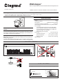
DLM - Occupancy Sensor PIR Corner Mount With One-Way Aisle Lens
Installation Instructions • Instructions d’Installation • Instrucciones de Instalación
No: 24782 – 09/16 rev. 1
Catalog Number • Numéro de Catalogue • Número de Catálogo: LMPX-100-4
Country of Origin: Made in China • Pays d’origine: Fabriqué en Chine • País de origen: Hecho en China
LMPX-100-4-U is BAA and TAA compliant (Product produced in the U.S.)
SPECIFICATIONS
Voltage .............................................................................. 24VDC
Current Consumption .............................................................7mA
Power Supply ................................Wattstopper Room Controllers
Connection to the DLM Local Network ........................ RJ-45 plug
DLM Local Network characteristics when using LMRC-11x/2xx
room controllers:
Low voltage power provided over Cat 5e cable (LMRJ);
max current 800mA. Supports up to 64 load addresses,
48 communicating devices including up to 4 LMRC-10x
series and/or LMPL-101 controllers.
Free topology up to 1,000’ max.
Environment ................................................. For Indoor Use Only
Operating Temperature .................32° to 131°F (0° to 55°C)
Storage Temperature ...................23° to 176°F (-5° to 80°C)
Relative Humidity .......................5 to 95% (non condensing)
Patent Pending
This unit is pre-set for Plug n’ Go™ operation, adjustment is
optional.
For full operational details, adjustment and more features of the product, see the
DLM System Installation Guide provided with Wattstopper room controllers, and
also available at www.legrand.us/wattstopper.
Installation shall be in accordance with all applicable regulations, local and
NEC codes. Wire connections shall be rated suitable for the wire size (lead and
building wiring) employed.
For Class 2 DLM devices and device wiring: To be connected to a Class 2 power
source only. Do not reclassify and install as Class 1, or Power and Lighting Wiring.
SENSOR PLACEMENT
COVERAGE PATTERN
Coverages shown are maximum and represent half-step walking motion.
15 ft.
30 ft.
0
3 ft
3 ft
30ft
0
15ft
10 ft 10 ft 20 ft 30 ft 40 ft 50 ft010 ft 10 ft 20 ft 30 ft 40 ft 50 ft0
33˚
Top View
Side View
Sensor
Ceiling

2
Room
Controller
J Box
Occupanc
y
Sensor
Switch
To
Load/Line
(Class 1 wiring)
DLM Local Network
(low voltage, Class 2)
LMRJ Cables
CAUTION: TO CONNECT A COMPUTER TO THE DLM LOCAL NETWORK USE THE
LMCI-100. NEVER CONNECT THE DLM LOCAL NETWORK TO AN ETHERNET
PORT – IT MAY DAMAGE COMPUTERS AND OTHER CONNECTED EQUIPMENT.
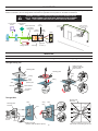
CONNECTIVITY
The illustrations below show examples of free-topology wiring. The LMPX-100-4 communicates to all other Digital Lighting Management
devices connected to the low voltage DLM Local Network, regardless of their position on the DLM Local Network.
Line
Voltage
Room
Controller
J-Boxes
Daylight Sensor
Switch
Switch
Corner Mount
Sensor
Ceiling Mount
Sensor
DLM Local Network
Low Voltage
LMRJ Cables
Loads
2
1
Line/Hot
Black wire
Neutral
White wire
Red wire
to Load A (1)
Yellow wire
to Load B (2)
LMRC
102
MOUNTING
WARNING: Do Not Install To Cover a Junction Box Having Class 1, 3 or Power and Lighting Circuits.
Through Ceiling Tile:
Through Wall:
Mounting plate
Ceiling
Hole
0.825”
(20.9mm) dia.
Stem
Base
Swivel bracket
Occupancy
Sensor
Ceiling
Mounting plate
Snug
Ring
Loose
Snug
Ring
Secure
Snug
Ring
LMRJ-C8 coupler
(included, LMRJ-S8
splitter optional)
Mounting plate
back view
European
3.5”
Octagon
4” Octagon
4” Square
2 Gang2 Gang 1 Gang
European
3.5”
Octagon
4” Octagon
4” Square
2 Gang2 Gang 1 Gang
Using a screwdriver, punch out the
holes for the corresponding junction box.
J-box
Wall
Mounting plate
and base
LMRJ-C8 coupler
(included, LMRJ-S8 splitter optional)
Occupancy
Sensor
Snug
Ring
Wall
Snug
Ring
Secure
Snug
Ring
Loose
Screw

3
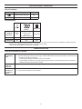
FACTORY PRE-SET OPERATION
Sensor Parameters
T-DELAY Time Delay 20 minutes
Passive Infrared Sensitivity 90%
WT Walk-Through OFF
Load Parameters
Load 1
Loads 2-8
or more**
Plug Load
ON Mode
Operation*
AUTO-
ON
MANUAL-ON
if switch is used.
AUTO-ON
if switch is not used.
AUTO-ON
Blink Warning OFF OFF OFF
Daylighting ON OFF OFF
NOTE: *Auto-OFF is enabled according to the sensor Time Delay when a sensor is bound to the load, regardless of whether the load
was turned on automatically with occupancy or manually using a switch.
** Max 8 loads using LMRC-100 series room controllers.
TROUBLESHOOTING
Loads do not operate as expected.
LEDs don’t
light, display
is off
1. Check to see that the sensor is connected to the DLM local Network.
2. Check for 24VDC input to the sensor: Plug in a different DLM device at the sensor location. If the device does
not power up, 24VDC is not present.
• Check the high voltage connections to the room controller.
• If high voltage connections are good and high voltage is present, recheck DLM local Network connections
between the sensor and the room controller.
The wrong
lights are
controlled
Configure the sensor to control the desired lights using the Push n’ Learn adjustment procedure.
LEDs turn ON
and OFF but
load doesn’t
switch
1. Make sure device is not in PnL.
2. Check load connections to room controller.

800.879.8585
www.legrand.us/wattstopper
No. 24782 – 09/16 rev. 1
© Copyright 2016 Legrand All Rights Reserved.
© Copyright 2016 Tous droits réservés Legrand.
© Copyright 2016 Legrand Todos los derechos reservados.
Wattstopper warranties its products to be free
of defects in materials and workmanship for a
period of five (5) years. There are no obligations
or liabilities on the part of Wattstopper for
consequential damages arising out of, or in
connection with, the use or performance of this
product or other indirect damages with respect
to loss of property, revenue or profit, or cost of
removal, installation or reinstallation.
Wattstopper garantit que ses produits sont
exempts de défauts de matériaux et de fabrication
pour une période de cinq (5) ans. Wattstopper
ne peut être tenu responsable de tout dommage
consécutif causé par ou lié à l’utilisation ou
à la performance de ce produit ou tout autre
dommage indirect lié à la perte de propriété, de
revenus, ou de profits, ou aux coûts d’enlèvement,
d’installation ou de réinstallation.
Wattstopper garantiza que sus productos
están libres de defectos en materiales y mano
de obra por un período de cinco (5) años. No
existen obligaciones ni responsabilidades por
parte de Wattstopper por daños consecuentes
que se deriven o estén relacionados con el
uso o el rendimiento de este producto u otros
daños indirectos con respecto a la pérdida
de propiedad, renta o ganancias, o al costo
de extracción, instalación o reinstalación.
WARRANTY INFORMATION INFORMATIONS RELATIVES À LA GARANTIE INFORMACIÓN DE LA GARANTÍA
-
 1
1
-
 2
2
-
 3
3
-
 4
4


wattstopper LMPX-100 Guide d'installation
- Taper
- Guide d'installation
dans d''autres langues
Documents connexes
-
wattstopper LMPX-100-1 DLM PIR Corner Mount Occupancy Sensor Guide d'installation
-
-
-
-
-
-