Milwaukee 0233-20 Manuel utilisateur
- Catégorie
- Marteaux rotatifs
- Taper
- Manuel utilisateur
Ce manuel convient également à

TO REDUCE THE RISK OF INJURY, USER MUST READ AND UNDERSTAND
OPERATOR'S MANUAL.
AFIN DE RÉDUIRE LE RISQUE DE BLESSURES, L'UTILISATEUR DOIT LIRE ET
BIEN COMPRENDRE LE MANUEL DE L'UTILISATEUR.
PARA REDUCIR EL RIESGO DE LESIONES, EL USUARIO DEBE LEER Y ENTENDER
EL MANUAL DEL OPERADOR.
OPERATOR'S MANUAL
MANUEL DE L'UTILISATEUR
MANUAL DEL OPERADOR
Catalog No.
No de Catalogue
Catálogo No.
HEAVY-DUTY MAGNUM DRILLS
EXTRA ROBUSTE PERCEUSES MAGNUM
TALADROS MAGNUM HEAVY-DUTY
0233-20
0234-1
0235-21
0244-1

2
need for the three wire grounded power
cord and grounded power supply sys-
tem.
6. Avoid body contact with grounded
surfaces such as pipes, radiators,
ranges and refrigerators. There is
an increased risk of electric shock if
your body is grounded.
7. Do not expose power tools to rain
or wet conditions. Water entering a
power tool will increase the risk of elec-
tric shock.
8. Do not abuse the cord. Never use
the cord to carry the tools or pull
the plug from an outlet. Keep cord
away from heat, oil, sharp edges
or moving parts. Replace damaged
cords immediately. Damaged cords
increase the risk of electric shock.
9. When operating a power tool out-
side, use an outdoor extension
cord marked “W-A” or “W”. These
cords are rated for outdoor use and re-
duce the risk of electric shock.
1. Keep your work area clean and well
lit. Cluttered benches and dark areas
invite accidents.
2. Do not operate power tools in ex-
plosive atmospheres, such as in
the presence of flammable liquids,
gases, or dust. Power tools create
sparks which may ignite the dust or
fumes.
3. Keep bystanders, children, and visi-
tors away while operating a power
tool. Distractions can cause you to lose
control. Protect others in the work area
from debris such as chips and sparks.
Provide barriers or shields as needed.
4. Grounded tools must be plugged
into an outlet properly installed and
grounded in accordance with all
codes and ordinances. Never re-
move the grounding prong or
modify the plug in any way. Do not
use any adaptor plugs. Check with
a qualified electrician if you are in
doubt as to whether the outlet is
properly grounded. If the tools should
electrically malfunction or break down,
grounding provides a low resistance
path to carry electricity away from the
user.
5. Double Insulated tools are
equipped with a polarized plug (one
blade is wider than the other). This
plug will fit in a polarized outlet only
one way. If the plug does not fit fully
in the outlet, reverse the plug. If it
still does not fit, contact a qualified
electrician to install a polarized out-
let. Do not change the plug in any
way. Double insulation eliminates the
10. Stay alert, watch what you are do-
ing, and use common sense when
operating a power tool. Do not use
tool while tired or under the influ-
ence of drugs, alcohol, or medica-
tion. A moment of inattention while op-
erating power tools may result in seri-
ous personal injury.
11. Dress properly. Do not wear loose
clothing or jewelry. Contain long
hair. Keep your hair, clothing, and
gloves away from moving parts.
Loose clothes, jewelry, or long hair can
be caught in moving parts.
12. Avoid accidental starting. Be sure
switch is off before plugging in.
Carrying tools with your finger on the
WORK AREA
ELECTRICAL SAFETY
PERSONAL SAFETY
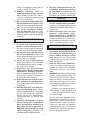
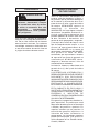
WARNING!
READ AND UNDERSTAND ALL INSTRUCTIONS
Failure to follow all instructions listed below, may result in
electric shock, fire and/or serious personal injury.
SAVE THESE INSTRUCTIONS
GENERAL SAFETY RULES

3
switch or plugging in tools with the
switch on invites accidents.
13. Remove adjusting keys or
wrenches before turning the tool
on. A wrench or a key that is left at-
tached to a rotating part of the tool may
result in personal injury.
14. Do not overreach. Keep proper foot-
ing and balance at all times. Proper
footing and balance enables better con-
trol of the tool in unexpected situations.
15. Use safety equipment. Always
wear eye protection. Dust mask, non-
skid safety shoes, hard hat, or hearing
protection must be used for appropriate
conditions.
16. Use clamps or other practical way
to secure and support the work-
piece to a stable platform. Holding
the work by hand or against your body is
unstable and may lead to loss of control.
17. Do not force tool. Use the correct
tool for your application. The correct
tool will do the job better and safer at the
rate for which it is designed.
18. Do not use tool if switch does not
turn it on or off. Any tool that cannot
be controlled with the switch is danger-
ous and must be repaired.
19. Disconnect the plug from the
power source before making any
adjustments, changing accesso-
ries, or storing the tool. Such pre-
ventive safety measures reduce the risk
of starting the tool accidentally.
20. Store idle tools out of reach of chil-
dren and other untrained persons.
Tools are dangerous in the hands of un-
trained users.
21. Maintain tools with care. Keep cut-
ting tools sharp and clean. Properly
maintained tools with sharp cutting edge
are less likely to bind and are easier to
control. Do not use a damaged tool.
Tag damaged tools “Do not use” until
repaired.
22. Check for misalignment or bind-
ing of moving parts, breakage of
parts, and any other condition that
may affect the tool’s operation. If
damaged, have the tool serviced
before using. Many accidents are
caused by poorly maintained tools.
23. Use only accessories that are rec-
ommended by the manufacturer
for your model. Accessories that may
be suitable for one tool, may become
hazardous when used on another tool.
24. Tool service must be performed
only by qualified repair personnel.
Service or maintenance performed by
unqualified personnel could result in a
risk of injury.
25. When servicing a tool, use only
identical replacement parts.
Follow instructions in the Mainte-
nance section of this manual. Use
of unauthorized parts or failure to fol-
low Maintenance Instructions may cre-
ate a risk of electric shock or injury.
1. Hold tool by insulated gripping sur-
faces when performing an opera-
tion where the cutting tool may
contact hidden wiring or its own
cord. Contact with a “live” wire will make
exposed metal parts of tool “live” and
shock the operator.
2. Maintain labels and nameplates.
These carry important information. If un-
readable or missing, contact a
MILWAU-
KEE
service facility for a free replace-
ment.
3. WARNING! Some dust created by power
sanding, sawing, grinding, drilling, and
other construction activities contains
chemicals known to cause cancer, birth
defects or other reproductive harm.
Some examples of these chemicals are:
• lead from lead-based paint
• crystalline silica from bricks and ce-
ment and other masonry products, and
• arsenic and chromium from chemi-
cally-treated lumber.
Your risk from these exposures varies,
depending on how often you do this
type of work. To reduce your exposure
to these chemicals: work in a well ven-
tilated area, and work with approved
safety equipment, such as those dust
masks that are specifically designed to
filter out microscopic particles.
TOOL USE AND CARE
SERVICE
SPECIFIC SAFETY RULES

4
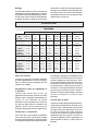
Amps
5.5
5.5
5.5
5.5
No Load
RPM
0-2800
without RAD 0-850
RAD low 0-565
RAD high 0-1275
0-850
without RAD 0-600
RAD low 0-400
RAD high 0-900
Volts
AC
120
120
120
120
Catalog
Number
0233-20
0234-1
0235-21
0244-1
Amperes
Double Insulated
Symbology
Canadian Standards
Association
Underwriters
Laboratories, Inc.
Volts Alternating
Current
No Load Revolutions
per Minute (RPM)
Specifications
Right Angle Drive Unit Cat. No. 48-06-2871
Mexican Approvals
Marking
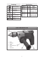
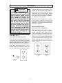
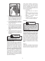
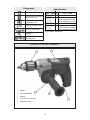
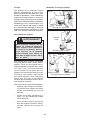
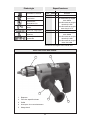
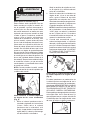
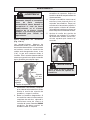
FUNCTIONAL DESCRIPTION
3
1. Chuck
2. Nameplate
3. Trigger
4. Forward/Reverse
switch
5. Side handle
5
1
2
4

5
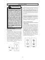
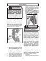
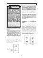
The grounding prong in the plug is con-
nected through the green wire inside the
cord to the grounding system in the tool.
The green wire in the cord must be the
only wire connected to the tool's ground-
ing system and must never be attached to
an electrically “live” terminal.
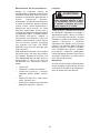
Your tool must be plugged into an appro-
priate outlet, properly installed and
grounded in accordance with all codes and
ordinances. The plug and outlet should look
like those in Figure A.
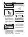
Double Insulated Tools:
Tools with Two Prong Plugs
Tools marked “Double Insulated” do not re-
quire grounding. They have a special
double insulation system which satisfies
OSHA requirements and complies with the
applicable standards of Underwriters Labo-
ratories, Inc., the Canadian Standard As-
sociation and the National Electrical Code.
Double Insulated tools may be used in ei-
ther of the 120 volt outlets shown in
Figures B and C.
Grounded Tools:
Tools with Three Prong Plugs
Tools marked “Grounding Required” have
a three wire cord and three prong ground-
ing plug. The plug must be connected to a
properly grounded outlet (See Figure A). If
the tool should electrically malfunction or
break down, grounding provides a low re-
sistance path to carry electricity away from
the user, reducing the risk of electric shock.
Fig. B
Fig. C
Fig. A
Improperly connecting the
grounding wire can result in the
risk of electric shock. Check
with a qualified electrician if you
are in doubt as to whether the
outlet is properly grounded. Do
not modify the plug provided
with the tool. Never remove the
grounding prong from the plug.
Do not use the tool if the cord or
plug is damaged. If damaged,
have it repaired by a
MILWAUKEE
service facility before use. If the
plug will not fit the outlet, have a
proper outlet installed by a
qualified electrician.
GROUNDING
WARNING!

6
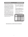
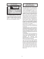
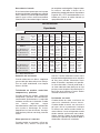
Grounded tools require a three wire ex-
tension cord. Double insulated tools can
use either a two or three wire extension
cord. As the distance from the supply out-
let increases, you must use a heavier
gauge extension cord. Using extension
cords with inadequately sized wire causes
a serious drop in voltage, resulting in loss
of power and possible tool damage. Refer
to the table shown to determine the re-
quired minimum wire size.
The smaller the gauge number of the wire,
the greater the capacity of the cord. For
example, a 14 gauge cord can carry a
higher current than a 16 gauge cord. When
using more than one extension cord to make
up the total length, be sure each cord con-
tains at least the minimum wire size re-
quired. If you are using one extension cord
for more than one tool, add the nameplate
amperes and use the sum to determine the
required minimum wire size.
Guidelines for Using Extension Cords
• If you are using an extension cord out-
doors, be sure it is marked with the
suffix “W-A” (“W” in Canada) to indi-
cate that it is acceptable for outdoor
use.
• Be sure your extension cord is prop-
erly wired and in good electrical
condition. Always replace a damaged
extension cord or have it repaired by a
qualified person before using it.
• Protect your extension cords from
sharp objects, excessive heat and
damp or wet areas.
READ AND SAVE ALL INSTRUCTIONS FOR FUTURE USE.
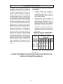
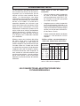
Recommended Minimum Wire
Gauge for Extension Cords*
Extension Cord Length
* Based on limiting the line voltage drop to
five volts at 150% of the rated amperes.
Nameplate
Amperes
0 - 2.0
2.1 - 3.4
3.5 - 5.0
5.1 - 7.0
7.1 - 12.0
12.1 - 16.0
16.1 - 20.0
25'
18
18
18
18
16
14
12
75'
18
18
16
14
12
10
100'
18
16
14
12
10
150'
16
14
12
12
50'
18
18
18
16
14
12
10
EXTENSION CORDS

7
TOOL ASSEMBLY
To reduce the risk of injury, al-
ways unplug tool before attaching
or removing accessories. Use
only specifically recommended
accessories. Others may be
hazardous.
WARNING!
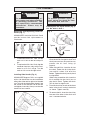
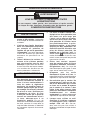
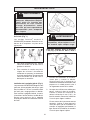
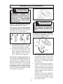
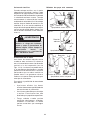
Removing and Replacing Quik-Lok
®
Cords (Fig. 1)
MILWAUKEE
's exclusive Quik-Lok
®
Cords
provide instant field replacement or
substitution.
Fig. 1
1. To remove the Quik-Lok
®
Cord, turn the
cord nut 1/4 turn to the left and pull it
out.
2. To replace the Quik-Lok
®
Cord, align the
connector keyways and push the con-
nector in as far as it will go. Turn the
cord nut 1/4 turn to the right to lock.
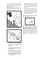
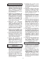
Installing Side Handle (Fig. 2)
MILWAUKEE
Magnum Drills are supplied
with a side handle that can be installed on
either side of the tool for right or left handed
use. To install the side handle, thread it into
the socket on the desired side of the tool
and tighten it securely. Always use the side
handle for best control.
To prevent personal injury, al-
ways remove the chuck key from
the chuck after each use.
WARNING!
Installing Bits into Keyed Chucks (Fig. 3)
Cat. No. 0234-1, 0244-1
1. Open the chuck jaws wide enough to
insert the bit. Be sure the bit shank and
chuck jaws are clean. Dirt particles may
prevent the bit from lining up
properly.
2. When using drill bits, insert the bit into
the chuck. Center the bit in the chuck
jaws and lift it about 1/16" off of the
bottom. Tighten the chuck jaws by hand
to align the bit.
When using screwdriver bits, insert the
bit far enough for the chuck jaws to
grip the bit shank. Tighten the chuck
jaws by hand to align the bit.
3. Place the chuck key in each of the three
holes in the chuck, turning it clockwise
as shown. Tighten securely.
4. To remove the bit, insert the chuck key
into one of the holes in the chuck and
turn it counterclockwise.
Fig. 2
Tighten
Loosen
Fig. 3

8
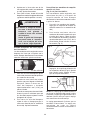
Chuck Removal (Fig. 7)
This tool is equipped with a threaded spindle
to hold the chuck. Before removing the
chuck, unplug the tool and open the chuck
jaws. A left-handed thread screw is lo-
cated inside the chuck to prevent the chuck
from loosening when the tool is operated
in reverse direction. Remove the screw by
turning it clockwise. To remove the chuck,
hold the tool so that only the side of the
chuck rests firmly and squarely on a solid
workbench. Insert the chuck key or a chuck
remover bar in one of the keyholes. Turn
the chuck so the key is at about a 30° angle
to the bench top and strike the key sharply
with a hammer so the chuck turns in a
counterclockwise direction (looking from
WARNING!
To reduce the risk of injury,
always wear eye protection.
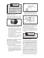
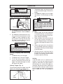
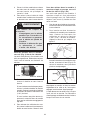
Installing Bits into Keyless Chucks
(Fig. 4) Cat. No. 0233-20
These tools are equipped with a hand-
tightening keyless chuck. Always unplug
the tool before installing or removing bits.
3. To close the chuck jaws, turn the chuck
sleeve in clockwise direction (Fig. 6).
Tighten securely. Several detents will
be felt as the chuck sleeve is turned.
1. To open the chuck jaws, turn the sleeve
in the counterclockwise direction.
When using drill bits, allow the bit to
strike the bottom of the chuck. Center
the bit in the chuck jaws and lift it about
1/16" off of the bottom.
When using screwdriver bits, insert the
bit far enough for the chuck jaws to
grip the hex of the bit.
2. To close the chuck jaws, hold the collar
while turning the sleeve in the clock-
wise direction. Tighten securely.
Installing Bits into Keyless Chucks
(Fig. 5 & 6) Cat. No. 0235-21
These tools are equipped with a spindle-
lock mechanism and a single-sleeve key-
less chuck. Always unplug the tool before
inserting or removing bits.
1. To open the chuck jaws, turn the chuck
sleeve in counterclockwise direction.
2. To install a bit, open the chuck jaws
slightly wider than the bit. Center the bit
in the chuck jaws and lift it about
1/16" off of the bottom. Align the bit as
shown (Fig. 5).
To reduce the risk of injury:
• Do not grasp the bit while the
chuck is rotating or while the
bit is falling from the chuck.
• Release the trigger as soon as
the ratcheting stops to avoid
throwing the bit.
WARNING!
Fig. 5
Fig. 6
Sleeve
To close
NOTE: If the spindle rotates when opening
or closing the chuck jaws, grasp the chuck
and slightly rotate back and forth to en-
gage the spindle-lock mechanism.
The spindle will remain locked until the tool
is turned on. The spindle-lock mechanism
will automatically disengage when the tool
is turned on.
Collar
Sleeve
Fig. 4
Cat. No. 0233-20

9
Fig. 7
the front of the tool). This should loosen
the chuck from the spindle which has a
right hand thread making it easy to remove
the chuck by hand.
NOTE: When replacing the chuck, always
replace the left hand thread screw in the
chuck.
Attaching Right Angle Drive to Drill
(Fig. 8)
Fig. 9
Fig. 8
1
2
3
4
5
1. Remove the chuck from the drill follow-
ing instructions (See “Removing the
Chuck From the Drill”). Slip the double
hex coupling (1) over the hex on the
drill spindle.
Loosen the clamping screws on the
clamping sleeve (2) and slip the sleeve
onto the drill collar.
2. Slide the Right Angle Drive head (4) into
the other side of the sleeve and turn
the drive head slightly in either direc-
tion so the hexagonal hole in the cou-
pling (1) engages the hexagonal por-
tion of the spindle (3).
The chuck can be removed from the Right
Angle Drive Unit in the same manner it is
removed from the drill; however, ALWAYS
REMOVE RIGHT ANGLE DRIVE FROM THE
DRILL BEFORE ATTEMPTING TO LOOSEN
THE CHUCK. This will prevent damaging
the drill's gearing. Use the open end wrench
provided to hold the Right Angle Drive
spindle before attempting to loosen the
chuck.
NOTE: Attaching the drill chuck to the
side marked “LOW” reduces the speed
by 1/3, or 33%. Attaching the drill chuck
to the opposite side increases the speed
by 50%.
3. When assembled, turn the Right Angle
Drive head to the desired position and
tighten the clamping screws to secure
the unit. Thread the chuck onto the
Right Angle Drive spindle (5). INSTALL
CHUCK LOCKING SCREW.
Removing the Chuck From Right
Angle Drive Unit (Fig. 9)

10
To reduce the risk of injury,
always wear eye protection.
WARNING!
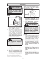
Using Forward/Reverse Switch (Fig. 10)
1. For forward (clockwise) rotation, push
the forward/reverse switch to FWD as
shown.
2. For reverse (counterclockwise) rota-
tion, push the forward/reverse switch
to REV as shown. Although an inter-
lock prevents reversing the tool while
the motor is running, allow it to come to
a full stop before reversing.
Locking Trigger (Fig. 11)
The lock button holds the trigger in the ON
position for continuous full speed use.
To reduce the risk of injury, keep
hands and cord away from the bit
and all moving parts.
WARNING!
OPERATION
Forward
Fig. 10
Trigger
Reverse
Lock
button
Fig. 11
Drilling
1. Before drilling, be sure the workpiece
is clamped securely. Use backing ma-
terial to prevent damage to the work-
piece during breakthrough.
2. When starting a hole, place the drill bit
on the work surface and apply firm
pressure. Begin drilling at a slow speed,
gradually increasing the speed as you
drill.
3. Always apply pressure in line with the
bit. Use enough pressure to keep the
drill biting, but do not push hard enough
to stall the motor.
4. Reduce pressure and ease the bit
through the last part of the hole. While
the tool is still running, pull the bit out of
the hole to prevent jamming.
Stalling
If the tool seems as if it is about to stall,
maintain a firm grip and reduce pressure
slightly to allow the bit to regain speed. If
the tool does stall, release the trigger im-
mediately. Reverse the motor, remove the
bit from the work and start again. Do not
pull the trigger on and off in an attempt to
start a stalled drill. This can damage the
drill.
Starting, Stopping and Controlling
Speed
1. To start the tool, pull the trigger.
2. To stop the tool, release the trigger.
3. To vary the drilling speed, simply in-
crease or decrease pressure on the
trigger. The further the trigger is pulled,
the greater the speed.
To reduce the risk of explosion,
electric shock and property
damage, always check the work
area for hidden pipes and wires
before drilling.
WARNING!
1. To lock the trigger, hold the lock button
in while pulling the trigger. Release the
trigger.
2. To unlock the trigger, pull the trigger
and release. The lock button will pop
out.

11
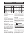
APPLICATIONS
Selecting Bits
When selecting a bit, use the right type for
your job. For best performance, always
use sharp bits.
Drilling in Wood, Composition Materi-
als and Plastic
When drilling in wood, composition materi-
als and plastic, start the drill slowly, gradu-
ally increasing speed as you drill. When
using twist drill bits, pull the bit out of the
hole frequently to clear chips from the bit
flutes. Use low speeds for plastics with a
low melting point.
Drilling in Masonry
When drilling in masonry, use high speed
carbide-tipped bits. Drilling soft masonry
materials such as cinder block requires little
pressure. Hard materials like concrete re-
quire more pressure. A smooth, even flow
of dust indicates the proper drilling rate.
Do not let the bit spin in the hole without
cutting. Do not use water to settle dust or
to cool bit. Both actions will damage the
carbide.
Drilling in Metal
When drilling in metal, use high speed steel
twist drills or hole saws. Use slow speeds
for hard metals and high speeds for softer
metals. Lubricate drill bits with cutting oil
when drilling in iron or steel. Use a coolant
when drilling in nonferrous metals such as
copper, brass or aluminum. Back the mate-
rial to prevent binding and distortion on
breakthrough.
Driving Screws
When driving screws, use the proper
screwdriver bit for your job. After drilling
pilot and shank holes, start the screw
slowly and increase the speed as driving
progresses. Set the screw by slowing to
a stop. Do not run screws down at exces-
sive speeds. To remove screws, reverse
the motor.
NR = Not recommended
CAPACITIES
Cat.
No.
0233-20
0234-1
RAD low
RAD high
0235-21
0244-1
RAD low
RAD high
Ship
Auger
Bits
N R
1-1/4"
1-1/2"
1"
1-1/4"
1-1/2"
1-1/2"
1-1/4"
Flat
Boring
Bits
1"
1-1/2"
1-1/2"
1-1/2"
1-1/2"
1-1/2"
1-1/2"
1-1/2"
Auger
Bits
N R
1-1/2"
1-1/2"
1-1/8"
1-1/2"
1-1/2"
1-1/2"
1-1/2"
Selfeed
Bits
N R
2"
2-1/4"
1-1/2"
2"
2-1/4"
2-9/16"
1-3/4"
Twist
Drill
3/8"
1/2"
1/2"
1/2"
1/2"
1/2"
1/2"
1/2"
Hole
Saws
1-3/4"
4"
4-1/2"
2-3/4"
4"
4-1/2"
5"
3-1/4"
Hole
Saws
1"
2"
2-1/8"
1-1/2"
2"
2-1/4"
2-1/4"
1-3/4"
Carbide-
Tipped
Bits
3/8"
1/2"
9/16"
7/16"
1/2"
9/16"
5/8"
1/2"
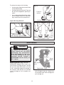
Wood Steel Masonry
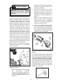
High rotational force. To reduce the
risk of injury, always hold or brace
secrely. Always use side handle on
tools rated 1200 RPM or less.
WARNING!
Bit Binding
A high rotational force occurs when a bit
binds. If the bit binds, the tool will be forced
in the opposite direction of the bit rotation
(See Fig. 12 - 14). Bits may bind if they are
misaligned or when they are breaking
through a hole. Wood boring bits can also
bind if they run into nails or knots. Be pre-
pared for bit binding situations.

12
Replacing Brushes (Fig. 15 & 16)
MILWAUKEE
Magnum Drills have an ex-
clusive Brush Cartridge System. The tool
will not start when the brushes are worn
to 1/8", preventing expensive damage to
the armature. New brushes are provided
in the Cartridge for fast changes any-
where.
Brush holder
screw
Brushes
Extra brushes
Brush
holder
Replacement screw
Fig. 15
To reduce the chance of bit binding:
• Use sharp bits. Sharp bits are less likely
to bind when drilling.
• Use the proper bit for the job. There are
bits that are designed for specific pur-
poses.
• Use caution when drilling pitchy, knotty,
wet or warped material or when drill-
ing in material that may contain nails.
Typical Bracing Methods
Fig. 12
Forward rotation
Reaction
Bracing against the floor
Fig. 13
Forward
rotation
Bracing against your leg
Reaction
Bracing against a stud
Fig. 14
Reverse rotation
Reaction
Forward rotation
MAINTENANCE
To reduce the risk of injury,
always unplug your tool before
performing any maintenance.
Never disassemble the tool or try
to do any rewiring on the tool's
electrical system. Contact a
MILWAUKEE
service facility for
ALL repairs.
WARNING!
1. Unplug tool and rest it on its side with
the cartridge facing up. Loosen the
brush holder screw in the cartridge and
pull cartridge out.

13
Fig. 16
2. Remove worn brushes. If the brushes
should fall into the tool, be sure to shake
them out before reinserting the car-
tridge. Discard BOTH brushes. Brushes
should always be replaced in sets.
3. A set of spare brushes is provided in
the cartridge. Remove the brushes from
storage compartment.
4. Position new brushes with the flat sil-
ver end facing into the brush holder.
Push cartridge into the tool and press
evenly on top and bottom of the car-
tridge to align terminals for proper con-
nection.
5. Tighten the brush holder screw gently.
If the head of Screw is damaged, use
the replacement screw provided in the
cartridge.
Never use a metal screw as a
brush holder screw.
WARNING!
Maintaining Tools
Keep your tool in good repair by adopting a
regular maintenance program. Before use,
examine the general condition of your tool.
Inspect guards, switches, tool cord set and
extension cord for damage. Check for
loose screws, misalignment, binding of
moving parts, improper mounting, broken
parts and any other condition that may af-
fect its safe operation. If abnormal noise
or vibration occurs, turn the tool off imme-
diately and have the problem corrected
before further use. Do not use a damaged
tool. Tag damaged tools “DO NOT USE” until
repaired (see “Repairs”).
Repairs
If your tool is damaged, return the entire
tool to the nearest service center listed on
the back cover of this operator’s manual.
To reduce the risk of injury,
electric shock and damage to the
tool, never immerse your tool in
liquid or allow a liquid to flow in-
side the tool.
WARNING!
Under normal conditions, relubrication is
not necessary until the motor brushes
need to be replaced. After six months to
one year, depending on use, return your
tool to the nearest
MILWAUKEE
service
facility for the following:
• Lubrication
• Brush inspection and replace-
ment
• Mechanical inspection and cleaning
gears, spindles, bearings, housing,
etc.)
• Electrical inspection (switch,
cord, armature, etc.)
• Testing to assure proper me-
chanical and electrical operation
Cleaning
Clean dust and debris from vents. Keep
the tool handles clean, dry and free of oil
or grease. Use only mild soap and a damp
cloth to clean your tool since certain clean-
ing agents and solvents are harmful to plas-
tics and other insulated parts. Some of
these include: gasoline, turpentine, lacquer
thinner, paint thinner, chlorinated cleaning
solvents, ammonia and household deter-
gents containing ammonia. Never use flam-
mable or combustible solvents around
tools.

14
WARNING!
Always unplug tool before
changing accessories. Only use
specifically recommended
accessories. Others may be haz-
ardous.
ACCESSORIES
For a complete listing of accessories refer
to your
MILWAUKEE
Electric Tool catalog
or go on-line to www.mil-electric-tool.com.
To obtain a catalog, contact your local dis-
tributor or a service center listed on the
back cover of this operator’s manual.
FIVE YEAR TOOL
LIMITED WARRANTY
Every
MILWAUKEE
tool is tested before
leaving the factory and is warranted to be
free from defects in material and work-
manship.
MILWAUKEE
will repair or re-
place (at
MILWAUKEE
’s discretion), with-
out charge, any tool (including battery
chargers) which examination proves to be
defective in material or workmanship from
five (5) years after the date of purchase.
Return the tool and a copy of the purchase
receipt or other proof of purchase to a
MILWAUKEE
Factory Service/Sales Sup-
port Branch location or
MILWAUKEE
Au-
thorized Service Station, freight prepaid
and insured. This warranty does not cover
damage from repairs made or attempted
by other than
MILWAUKEE
authorized per-
sonnel, abuse, normal wear and tear, lack
of maintenance, or accidents.
Battery Packs, Flashlights, and Radios are
warranted for one (1) year from the date
of purchase.
THE REPAIR AND REPLACEMENT REMEDIES
DESCRIBED HEREIN ARE EXCLUSIVE. IN NO
EVENT SHALL
MILWAUKEE
BE LIABLE
FOR ANY INCIDENTAL, SPECIAL, OR CON-
SEQUENTIAL DAMAGES, INCLUDING LOSS
OF PROFITS.
THIS WARRANTY IS EXCLUSIVE AND IN
LIEU OF ALL OTHER WARRANTIES, OR
CONDITIONS, WRITTEN OR ORAL, EX-
PRESSED OR IMPLIED FOR
MERCHANTABLILITY OR FITNESS FOR
PARTICULAR USE OR PURPOSE.
This warranty gives you specific legal
rights. You may also have other rights that
vary from state to state and province to
province. In those states that do not allow
the exclusion of implied warranties or limi-
tation of incidental or consequential dam-
ages, the above limitations or exclusions
may not apply to you. This warranty ap-
plies to the United States, Canada, and
Mexico only.

15
VOUS DEVEZ LIRE ET COMPRENDRE TOUTES
LES INSTRUCTIONS
Le non-respect, même partiel, des instructions ci-après entraîne
un risque de choc électrique, d'incendie et/ou de blessures graves.
CONSERVEZ CES INSTRUCTIONS
1. Veillez à ce que l’aire de travail soit
propre et bien éclairée. Le désordre
et le manque de lumière favorisent les
accidents.
2. N’utilisez pas d’outils électriques
dans une atmosphère explosive,
par exemple en présence de
liquides, de gaz ou de poussières
inflammables. Les outils électriques
créent des étincelles qui pourraient
enflammer les poussières ou les
vapeurs.
3. Tenez à distance les curieux, les
enfants et les visiteurs pendant
que vous travaillez avec un outil
électrique. Ils pourraient vous distraire
et vous faire faire une fausse manoeu-
vre. Installez des barrières ou des
écrans protecteurs si nécessaire.
RÈGLES DE SÉCURITÉ GÉNÉRALES
4. Les outils mis à la terre doivent
être branchés dans une prise de
courant correctement installée et
mise à la terre conformément à
tous les codes et règlements
pertinents. Ne modifiez jamais la
fiche de quelque façon que ce soit,
par exemple en enlevant la broche
de mise à la terre. N’utilisez pas
d’adaptateur de fiche. Si vous
n’êtes pas certain que la prise de
courant est correctement mise à
la terre, adressez-vous à un
électricien qualifié. En cas de
défaillance ou de défectuosité électrique
de l’outil, une mise à la terre offre un
trajet de faible résistance à l’électricité
qui autrement risquerait de traverser
l’utilisateur.
5. Les outils à double isolation sont
équipés d’une fiche polarisée (une
des lames est plus large que
l’autre), qui ne peut se brancher
que d’une seule façon dans une
prise polarisée. Si la fiche n’entre
pas parfaitement dans la prise,
inversez sa position ; si elle n’entre
toujours pas bien, demandez à un
électricien qualifié d’installer une
prise de courant polarisée. Ne
modifiez pas la fiche de l’outil. La
double isolation élimine le besoin d’un
cordon d’alimentation à trois fils avec
mise à la terre ainsi que d’une prise de
courant mise à la terre.
6. Évitez tout contact corporel
avec des surfaces mises à la terre
(tuyauterie, radiateurs, cuisinières,
réfrigérateurs, etc.). Le risque de
choc électrique est plus grand si votre
corps est en contact avec la terre.
7. N’exposez pas les outils
électriques à la pluie ou à l’eau. La
présence d’eau dans un outil électrique
augmente le risque de choc électrique.
8. Ne maltraitez pas le cordon. Ne
transportez pas l’outil par son cor-
don et ne débranchez pas la fiche
en tirant sur le cordon. N’exposez
pas le cordon à la chaleur, à des
huiles, à des arêtes vives ou à des
pièces en mouvement. Remplacez
immédiate-ment un cordon
endommagé. Un cordon endommagé
augmente le risque de choc électrique.
9. Lorsque vous utilisez un outil
électrique à l’extérieur, employez
un prolongateur pour l’extérieur
marqué « W-A » ou « W ». Ces cor-
dons sont faits pour être utilisés à
l’extérieur et réduisent le risque de choc
électrique.
AVERTISSEMENT!
AIRE DE TRAVAIL
SÉCURITÉ ÉLECTRIQUE

16
10. Restez alerte, concentrez-vous sur
votre travail et faites preuve de
jugement. N’utilisez pas un outil
électrique si vous êtes fatigué ou
sous l’influence de drogues,
d’alcool ou de médicaments. Un in-
stant d’inattention suffit pour entraîner
des blessures graves.
11. Habillez-vous convenablement. Ne
portez ni vêtements flottants ni
bijoux. Confinez les cheveux longs.
N’approchez jamais les cheveux,
les vêtements ou les gants des
pièces en mouvement. Des
vêtements flottants, des bijoux ou des
cheveux longs risquent d’être happés
par des pièces en mouvement.
12. Méfiez-vous d’un démarrage
accidentel. Avant de brancher
l’outil, assurez-vous que son
interrupteur est sur ARRÊT. Le fait
de transporter un outil avec le doigt sur
la détente ou de brancher un outil dont
l’interrupteur est en position MARCHE
peut mener tout droit à un accident.
13. Enlevez les clés de réglage ou de
serrage avant de démarrer l’outil.
Une clé laissée dans une pièce tournante
de l’outil peut provoquer des blessures.
14. Ne vous penchez pas trop en avant.
Maintenez un bon appui et restez
en équilibre en tout temps. Un
bonne stabilité vous permet de mieux
réagir à une situation inattendue.
15. Utilisez des accessoires de
sécurité. Portez toujours des lu-
nettes ou une visière. Selon les con-
ditions, portez aussi un masque
antipoussière, des bottes de sécurité
antidérapantes, un casque protecteur
et/ou un appareil antibruit.
16. Immobilisez le matériau sur une sur-
face stable au moyen de brides ou
de toute autre façon adéquate. Le fait
de tenir la pièce avec la main ou contre
votre corps offre une stabilité insuffisante
et peut amener un dérapage de l’outil.
17. Ne forcez pas l’outil. Utilisez l’outil
approprié à la tâche. L’outil correct
fonctionne mieux et de façon plus
sécuritaire. Respectez aussi la vitesse de
travail qui lui est propre.
18. N’utilisez pas un outil si son
interrupteur est bloqué. Un outil que
vous ne pouvez pas commander par
son interrupteur est dangereux et doit
être réparé.
19. Débranchez la fiche de l’outil avant
d’effectuer un réglage, de changer
d’accessoire ou de ranger l’outil.
De telles mesures préventives de
sécurité réduisent le risque de
démarrage accidentel de l’outil.
20. Rangez les outils hors de la portée
des enfants et d’autres personnes
inexpérimentées. Les outils sont
dangereux dans les mains d’utilisateurs
novices.
21. Prenez soin de bien entretenir les
outils. Les outils de coupe doivent
être toujours bien affûtés et
propres. Des outils bien entretenus,
dont les arêtes sont bien tranchantes,
sont moins susceptibles de coincer et
plus faciles à diriger. N’utilisez pas un
outil défectueux. Fixez-y une étiquette
marquée « Hors d’usage » jusqu’à ce
qu’il soit réparé.
22. Soyez attentif à tout désalignement
ou coincement des pièces en
mouvement, à tout bris ou à toute
autre condition préjudiciable au
bon fonctionnement de l’outil. Si
vous constatez qu’un outil est
endommagé, faites-le réparer
avant de vous en servir. De nombreux
accidents sont causés par des outils en
mauvais état.
23. N’utilisez que des accessoires que
le fabricant recommande pour
votre modèle d’outil. Certains
accessoires peuvent convenir à un outil,
mais être dangereux avec un autre.
24. La réparation des outils électriques
doit être confiée à un réparateur
qualifié. L’entretien ou la réparation d’un
outil électrique par un amateur peut avoir
des conséquences graves.
25. Pour la réparation d’un outil,
n’employez que des pièces de
rechange d’origine. Suivez les di-
rectives données à la section
« Réparation » de ce manuel. L’emploi
de pièces non autorisées ou le
non-respect des instructions d’entretien
peut créer un risque de choc électrique
ou de blessures.
SÉCURITÉ DES PERSONNES
RÉPARATION
UTILISATION ET ENTRETIEN
DES OUTILS

17
RÈGLES DE SÉCURITÉ PARTICULIÈRE
1. Tenez l’outil par ses parties isolées lorsqu’il y a risque de contact de l’outil
avec des fils sous tension ou même, le cordon de l’outil. Le contact d’une partie
métallique de l’outil avec un fil sous tention comporte un risque de choc électrique.
2. Entretenez les étiquettes et marqies di fabricant. Les indications qu'elles
contiennent sont précieuses. Si elles deviennent illisibles ou se détachent, faites-les
remplacer gratuitement à un centre de service
MILWAUKEE
accrédité.
3. AVERTISSEMENT! La poussière degage par perçage, sclage, perçage et autres travaux
de construction contient des substances chimiques reconnues comme pouvant causer
le cancer, des malformations congénitales ou d’autres troubles de reproduction. Voici
quelques exemples de telles substances :
• Le plomb contenu dans la peinture au plomb.
• Le silice cristallin contenu dans la brique, le béton et divers produits de maçonnerie.
• L’arsenic et le chrome servant au traitement chimique du bois.
Les risque associés à l’exposition à ces substances varient, dépendant de la fréquence
des travaux. Afin de minimiser l’exposition à ces substances chimiques, assurez-vous
de travailler dans un endroit bien aéré et d’utiliser de l’equipement de sécurité tel un
masque antipoussière spécifiquement conçu pour la filtration de particules
microscopiques.

18
DESCRIPTION FONCTIONNELLE
3
5
1
2
4
1. Mandrin
2. Fiche signalétique
3. Détente
4. L'inverseur de rotation
5. Poignée latérale
Ampères
Double Isolation
Underwriters
Laboratories Inc.
Courant alternatif seul.
T/Min. á vide (RPM)
Pictographie
l’Association canadienne
de normalisation
A
5,5
5,5
5,5
5,5
T-min. à vide
0 - 2 800
sans l'unité coudée 0-850
l'unité coudée bas 0-565
l'unité coudée haut 0-1 275
0-850
sans l'unité coudée 0-600
l'unité coudée bas 0-400
l'unité coudée haut 0-900
Volts
120
120
120
120
No de
cat.
0233-20
0234-1
0235-21
0244-1
l'unité coudée 48-06-2871
Inscription mexicaine
d’approbation
Spécifications

19
Outils mis à la terre :
Outils pourvus d’une fiche de cordon
à trois dents
Les outils marqués « Mise à la terre requise
» sont pourvus d’un cordon à trois fils dont
la fiche a trois dents. La fiche du cordon
doit être branchée sur une prise
correctement mise à la terre (voir Figure A).
De cette façon, si une défectuosité dans
le circuit électrique de l’outil survient, le
relais à la terre fournira un conducteur à
faible résistance pour décharger le cou-
rant et protéger l’utilisateur contre les
risques de choc électrique.
La dent de mise à la terre de la fiche est
reliée au système de mise à la terre de
l’outil via le fil vert du cordon. Le fil vert du
cordon doit être le seul fil raccordé à un
bout au système de mise à la terre de l’outil
et son autre extrémité ne doit jamais être
raccordée à une borne sous tension
électrique.
Votre outil doit être branché sur une prise
appropriée, correctement installée et mise
à la terre conformément aux codes et
ordonnances en vigueur. La fiche du cor-
don et la prise de courant doivent être
semblables à celles de la Figure A.
Outils à double isolation :
Outils pourvus d’une fiche de cordon
à deux dents
Les outils marqués « Double Isolation » n’ont
pas besoin d’être raccordés à la terre. Ils
sont pourvus d’une double isolation
conforme eux exigences de l’OSHA et
satisfont aux normes de l’Underwriters
Laboratories, Inc., de l’Association
canadienne de normalisation (ACNOR) et
du « National Electrical Code » (code na-
tional de l’électricité). Les outils à double
isolation peuvent être branchés sur
n’importe laquelle des prises à 120 volt
illustrées ci-contre Figure B et C.
Fig. A
Si le fil de mise à la terre est
incorrectement raccordé, il peut
en résulter des risques de choc
électrique. Si vous n’êtes pas
certain que la prise dont vous
vous servez est correctement
mise à la terre, faites-la vérifier
par un électricien. N’altérez pas la
fiche du cordon de l’outil.
N’enlevez pas de la fiche, la dent
qui sert à la mise à la terre.
N’employez pas l’outil si le cordon
ou la fiche sont en mauvais état.
Si tel est le cas, faites-les
réparer dans un centre-service
MILWAUKEE
accrédité avant de
vous en servir. Si la fiche du cor-
don ne s’adapte pas à la prise,
faites remplacer la prise par un
électricien.
AVERTISSEMENT!
MISE A LA TERRE
Fig. B
Fig. C

20
Si l’emploi d’un cordon de rallonge est
nécessaire, un cordon à trois fils doit être
employé pour les outils mis à la terre. Pour
les outils à double isolation, on peut em-
ployer indifféremment un cordon de
rallonge à deux ou trois fils. Plus la longueur
du cordron entre l’outil et la prise de cou-
rant est grande, plus le calibre du cordon
doit être élevé. L’utilisation d’un cordon de
rallonge incorrectement calibré entraîne
une chute de voltage résultant en une perte
de puissance qui risque de détériorer l’outil.
Reportez-vous au tableau ci-contre pour
déterminer le calibre minimum du cordon.
Moins le calibre du fil est élevé, plus sa
conductivité est bonne. Par exemple, un
cordon de calibre 14 a une meilleure
conductivité qu’un cordon de calibre 16.
Lorsque vous utilisez plus d’une rallonge
pour couvrir la distance, assurez-vous que
chaque cordon possède le calibre minimum
requis. Si vous utilisez un seul cordon pour
brancher plusieurs outils, additionnez le
chiffre d’intensité (ampères) inscrit sur la
fiche signalétique de chaque outil pour
obtenir le calibre minimal requis pour le
cordon.
CORDONS DE RALLONGE
LISEZ ATTENTIVEMENT CES INSTRUCTIONS ET CONSERVEZ-LES
POUR LES CONSULTER AU BESOIN.
Directives pour l’emploi des cordons
de rallonge
• Si vous utilisez une rallonge à
l’extérieur, assurez-vous qu’elle est
marquée des sigles « W-A » (« W » au
Canada) indiquant qu’elle est adéquate
pour usage extérieur.
• Assurez-vous que le cordon de
rallonge est correctement câblé et en
bonne condition. Remplacez tout cor-
don derallonge détérioré ou faites-le
remettre en état par une personne
compétente avant de vous en servir.
• Tenez votre cordon de rallonge à l’écart
des objets ranchants, des sources de
grande chaleur et des endroits humides
ou mouillés.
Calibres minimaux recommandés
pour les cordons de rallonge*
Longueur du cordon de
rallonge (m)
Fiche
signalétique
Ampères
0 - 5,0
5,1 - 8,0
8,1 - 12,0
12,1 - 15,0
15,1 - 20,0
7,6
16
16
14
12
10
22,8
16
14
12
10
10
45,7
12
10
--
--
--
60,9
12
--
--
--
--
15,2
16
16
14
12
10
30,4
14
12
10
10
--
* Basé sur sur une chute de voltage limite
de 5 volts à 150% de l’intensité moyenne
de courant.
La page est en cours de chargement...
La page est en cours de chargement...
La page est en cours de chargement...
La page est en cours de chargement...
La page est en cours de chargement...
La page est en cours de chargement...
La page est en cours de chargement...
La page est en cours de chargement...
La page est en cours de chargement...
La page est en cours de chargement...
La page est en cours de chargement...
La page est en cours de chargement...
La page est en cours de chargement...
La page est en cours de chargement...
La page est en cours de chargement...
La page est en cours de chargement...
La page est en cours de chargement...
La page est en cours de chargement...
La page est en cours de chargement...
La page est en cours de chargement...
La page est en cours de chargement...
La page est en cours de chargement...
La page est en cours de chargement...
La page est en cours de chargement...
-
 1
1
-
 2
2
-
 3
3
-
 4
4
-
 5
5
-
 6
6
-
 7
7
-
 8
8
-
 9
9
-
 10
10
-
 11
11
-
 12
12
-
 13
13
-
 14
14
-
 15
15
-
 16
16
-
 17
17
-
 18
18
-
 19
19
-
 20
20
-
 21
21
-
 22
22
-
 23
23
-
 24
24
-
 25
25
-
 26
26
-
 27
27
-
 28
28
-
 29
29
-
 30
30
-
 31
31
-
 32
32
-
 33
33
-
 34
34
-
 35
35
-
 36
36
-
 37
37
-
 38
38
-
 39
39
-
 40
40
-
 41
41
-
 42
42
-
 43
43
-
 44
44


Milwaukee 0233-20 Manuel utilisateur
- Catégorie
- Marteaux rotatifs
- Taper
- Manuel utilisateur
- Ce manuel convient également à
dans d''autres langues
- English: Milwaukee 0233-20 User manual
- español: Milwaukee 0233-20 Manual de usuario
Documents connexes
-
Milwaukee 0233-20 Manuel utilisateur
-
-
Milwaukee 5392-1 Manuel utilisateur
-
-
Milwaukee 1107-1 Manuel utilisateur
-
-
-
-
Milwaukee 1250-1 Le manuel du propriétaire
-