Frigidaire PCFG3078AF Guide d'installation
- Catégorie
- Micro-ondes
- Taper
- Guide d'installation

1
INSTALLATION INSTRUCTIONS
FRONT CONTROL FREESTANDING GAS RANGE
INSTALLATION AND SERVICE MUST BE
PERFORMED BY A QUALIFIED INSTALLER.
IMPORTANT: SAVE FOR LOCAL ELECTRICAL INSPECTOR'S USE.
READ AND SAVE THESE INSTRUCTIONS FOR FUTURE REFERENCE.
IMPORTANT SAFETY INSTRUCTIONS
If the information in this manual is not followed
exactly, a re or electrical shock may result causing property
damage, personal injury or death.
FOR YOUR SAFETY:
— Do not store or use gasoline or other ammable vapors
and liquids in the vicinity of this or any other appliance.
— WHAT TO DO IF YOU SMELL GAS:
• Do not try to light any appliance.
• Do not touch any electrical switch; do not use any phone
in your building.
• Immediately call your gas supplier from a neighbor’s
phone. Follow the gas supplier’s instructions.
• If you cannot reach your gas supplier, call the re
department.
— Installation and service must be performed by a qualied
installer, service agency or the gas supplier.
Important Notes to the Installer:
• Read all instructions contained in these installation
instructions before installing range.
• Remove all packing material from the oven
compartments before connecting the gas & electrical
supply to the range.
• Observe all governing codes and ordinances.
• Be sure to leave these instructions with the
consumer.
Important Notes to the Consumer:
Keep these instructions with your owner’s guide for future
reference.
• As when using any appliance generating heat, there
are certain safety precautions you should follow.
These are listed in the Use & Care Guide, read it
carefully.
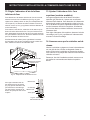
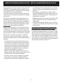
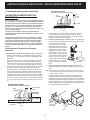
Tip Over Hazard
Range
leveling leg
Anti-tip
bracket
• A child or adult can tip the
range and be killed.
• Verify the anti-tip device has
been installed to floor or wall.
• Ensure the anti-tip device is re-engaged to floor
or wall when the range is moved.
• Do not operate the range without the anti-tip
device in place and engaged.
• Failure to follow these instructions can result in
death or serious burns to children and adults.
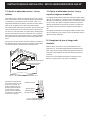
To check if the anti-tip bracket is installed properly, use
both arms to grasp the rear edge of the range back.
Carefully attempt to tilt range forward. When properly
installed, the range should not tilt forward.
Refer to the anti-tip bracket installation instructions
supplied with your range for proper installation.
FOR YOUR SAFETY: Do not
store or use gasoline or other ammable
vapors and liquids in the vicinity of this or
any other appliance.
• Be sure your range is installed and grounded properly
by a qualied installer or service technician.
• Make sure the wall coverings around the range can
withstand the heat generated by the range.
• To eliminate the need to reach over the surface
elements, cabinet storage space above the elements
should be avoided.
P/N 809127208 (2020/06) Rev. A
English – pages 1-13
French – pages 14-26
Spanish – pages 27-40

2
30” GAS FRONT CONTROL FREESTANDING INSTALLATION INSTRUCTIONS
IMPORTANT SAFETY INSTRUCTIONS
Provide proper fuel type
Before proceeding: Your range is factory preset to operate on
natural gas. If L.P. conversion is needed, contact your local L.P.
Gas provider for assistance.
The L.P. conversion kit may be located on the lower rear back
panel of the range. If no L.P. kit is provided, contact your product
dealer to obtain the correct L.P. conversion kit.
• Installation of this range must conform with local codes or, in
the absence of local codes, with the National Fuel Gas Code
ANSI Z223.1—latest edition when installed in the United
States.
• When installed in a manufactured (mobile) home, installation
must conform with the Manufactured Home Construction
and Safety Standard, Title 24 CFR, Part 3280 [formerly
the Federal Standard for Mobile Home Construction and
Safety, Title 24, HUD (Part 280)] or, when such standard
is not applicable, the Standard for Manufactured Home
Installations, ANSI/NCSBCS A225.1, or with local codes.
• This range has been design certied by CSA Group. As with
any appliance using gas and generating heat, there are
certain safety precautions you should follow. You will nd
them in the Use & Care Guide, read it carefully.
• Be sure your range is installed and grounded properly by a
qualied installer or service technician.
• This range must be electrically grounded in accordance with
local codes or, in their absence, with the National Electrical
Code ANSI/NFPA No .70—latest edition when installed in the
United States. See Grounding Instructions on page 9.
• All materials used in construction of cabinets, enclosures,
and supports surrounding the product must have a
temperature rating above 200°F (94°C).
• Before installing the range in an area covered with linoleum
or any other synthetic oor covering, make sure the oor
covering can withstand heat at least 90°F above room
temperature without shrinking, warping or discoloring. Do
not install the range over carpeting unless you place an
insulating pad or sheet of 1/4-inch thick plywood between the
range and carpeting.
• Make sure the wall coverings around the range can
withstand the heat generated by the range.
• Do not obstruct the ow of combustion air at the oven vent
nor around the base or beneath the lower front panel of the
range. Avoid touching the vent openings or nearby surfaces
as they may become hot while the oven is in operation. This
range requires fresh air for proper burner combustion.
• Air curtain or other overhead range hoods, which operate by
blowing a downward air ow on to a range or cooktop, shall
not be used in conjunction with gas ranges other than when
the hood and range have been designed, tested and listed
by an independent test laboratory for use in combination with
each other.
DO NOT MAKE ANY ATTEMPT TO OPERATE
THE ELECTRIC IGNITION OVEN DURING AN ELECTRICAL
POWER FAILURE. RESET ALL OVEN CONTROLS TO “OFF”
IN THE EVENT OF A POWER FAILURE.
The electric ignitor will automatically re-ignite the oven burner
when power resumes if the oven thermostat control was left in
the “ON” position.
When an electrical power failure occurs during use, the surface
burners will continue to operate.
During a power outage, the surface burners can be lit with a
match. Hold a lighted match to the burner, then slowly turn the
knob to the LITE position. Use extreme caution when lighting
burners this way.
Never leave children alone or
unattended in the area where an appliance is in use. Teach chil-
dren the proper, safe use of all appliances. Never leave the oven
door open when the range is unattended.
Stepping, leaning or sitting on the doors or
drawers of this range can result in serious injuries and can also
cause damage to the range.
• Do not store items of interest to children in the cabinets
above the range. Children could be seriously burned
climbing on the range to reach items.
• To eliminate the need to reach over the surface burners,
cabinet storage space above the burners should be avoided.
• Adjust surface burner ame size so it does not extend
beyond the edge of the cooking utensil. Excessive ame is
hazardous.
• Do not use the oven as a storage space. This creates a
potentially hazardous situation.
• Never use your range for warming or heating the room.
Prolonged use of the range without adequate ventilation can
be dangerous.
• Do not store or use gasoline or other ammable vapors and
liquids near this or any other appliance. Explosions or res
could result.
• Reset all controls to the “OFF” position after using a
programmable timing operation.
• Unlike some gas ranges, the cooktop is not removable. Do
not attempt to remove the cooktop.
Special instructions for appliances installed in the state of
Massachusetts:
This Appliance can only be installed in the state
of Massachusetts by a Massachusetts licensed plumber or gas
tter. When using a exible connector, it must not exceed three
(3) feet (36 in.) long. A “T” handle type manual gas valve must be
installed in the gas supply line to this appliance.

3
30” GAS FRONT CONTROL FREESTANDING INSTALLATION INSTRUCTIONS
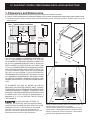
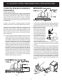
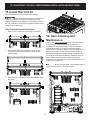
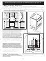
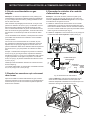
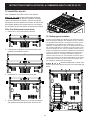
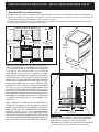
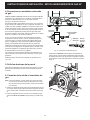
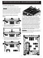
1. Clearances and Dimensions
a. Provide adequate clearances between the range and adjacent combustible surfaces.
b. Location—Check location where the range will be installed. Check for proper electrical supply and gas supply and the stability of oor.
c. Dimensions that are shown must be used. Given dimensions provide minimum clearance. Contact surface must be
solid and level.
WALL
OR
CABINET
WALL
OR
CABINET
Gas location
Open space
for gas
This space
must
remain clear
5”
30” Minimum*
Minimum to
wall on either
side of range
above 36” height.
36”
18”
Minimum to
cabinets on
either side
of range
25” Max.
13”
Maximum depth
for cabinets
above range top.
0” clearance below cooking top and at rear of range
Typical cabinet installationFront
view
Side
view
30”
Minimum
30”
Minimum
*30" (762 mm) MINIMUM CLEARANCE BETWEEN THE
TOP OF THE COOKING SURFACE AND THE BOTTOM
OF AN UNPROTECTED WOOD OR METAL CABINET; OR
24" (610 mm) MINIMUM WHEN BOTTOM OF WOOD OR
METAL CABINET IS PROTECTED BY NOT LESS THAN
1/4" (6 mm) FLAME RETARDANT MILLBOARD COVERED
WITH NOT LESS THAN NO. 28 MSG SHEET STEEL, 0.015"
(0.4 mm) STAINLESS STEEL, 0.024" (0.6 mm) ALUMINUM
OR 0.020" (0.5 mm) COPPER. 0" (0 mm) CLEARANCE IS
THE MINIMUM FOR THE REAR OF THE RANGE. FOLLOW
ALL DIMENSION REQUIREMENTS PROVIDED ABOVE
TO PREVENT PROPERTY DAMAGE, POTENTIAL FIRE
HAZARD, AND INCORRECT COUNTERTOP AND CABINET
CUTS.
TO ELIMINATE THE RISK OF BURNS OR FIRE BY
REACHING OVER HEATED SURFACE UNITS, CABINET
STORAGE SPACE LOCATED ABOVE THE SURFACE UNITS
SHOULD BE AVOIDED. IF CABINET STORAGE IS TO BE
PROVIDED, THE RISK CAN BE REDUCED BY INSTALLING
A RANGE HOOD THAT PROJECTS HORIZONTALLY A
MINIMUM OF 5" (127 mm) BEYOND THE BOTTOM OF
THE CABINETS.
DO NOT MAKE ANY ATTEMPT TO
OPERATE THE ELECTRIC IGNITION OVEN DURING
AN ELECTRICAL POWER FAILURE. RESET ALL OVEN
CONTROLS TO OFF IN THE EVENT OF A POWER
FAILURE. The electric ignitor will automatically re-
ignite the oven burner when power resumes if the oven
thermostat control was left in the ON position.
When an electrical power failure occurs during use, the
surface burners will continue to operate.
During a power outage, the surface burners can be lit
with a match. Hold a lighted match to the burner, then
slowly turn the knob to the Lite position. Use extreme
caution when lighting burners this way.
29
7
/
8
"
Maximum
36
5
/
8
"
±
1
/
4
"
26
6
/
8
"
47"
Door open
8"
4
1
/
3
"
12
1
/
16
"
24
1
/
8
"
22
5
/
8
"
4"
6
1
/
2
"
Fig.1
Fig.2
Fig.3

4
30” GAS FRONT CONTROL FREESTANDING INSTALLATION INSTRUCTIONS
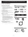
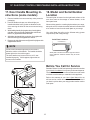
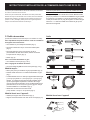
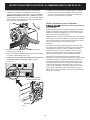
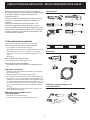
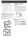
2. Tools You Will Need
Fig. a
(Wear safety glasses when using tools):
For leveling legs and Anti-Tip Bracket:
• Adjustable wrench or channel lock pliers (Fig. a)
• 5/16” Nutdriver or at head screwdriver (Fig. b)
• Electric drill & 1/8” drill bit (3/16” Masonry drill bit if
installing in concrete) (Fig. c)
• Level (Fig. d)
For gas supply connection:
• Adjustable wrench and pipe wrench (Figs. a & e)
For burner ame adjustment:
• Phillips head and small at-blade screwdrivers (Figs. f
& g)
Materials you will need:
• Pipe joint sealant that resists action of LP/Propane gas
(Fig. h)
• Gas line manual shut-o valve (Fig. i)
• A new exible metal appliance conduit (1/2” NPT x
3/4” or 1/2” I.D.) must be design certied by CSA
International. Because solid pipe restricts moving the
range, we recommend using a new exible conduit
(4 to 5 foot length) for each new installation and
additional reinstallations. (Fig. j)
• Use new are union adapters (1/2” NPT x 3/4” or 1/2”
I.D.) (Fig. k)
Materials supplied with appliance:
• Anti-Tip Template (Fig. l)
• Anti-Tip bracket; includes 2 mounting screws (Fig. m)
Tools
Fig. f
Materials
Fig. h
Fig. i
Fig. j
Fig. k
Fig. d
Fig. c
Fig. g
Fig. b
Fig. e
Fig. l
Fig. m
Materials supplied with appliance

5
30” GAS FRONT CONTROL FREESTANDING INSTALLATION INSTRUCTIONS
For oor mount, locate the bracket by placing back edge
of the template where the rear of the range will be located.
Mark the location of the screw holes, shown in template.
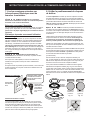
B. Drill Pilot Holes and Fasten
Bracket - Drill a 1/8” (3 mm)
pilot hole where screws are
to be located. If bracket is to
be mounted to the wall, drill
pilot hole at an approximate
20° downward angle. If
bracket is to be mounted to
masonry or ceramic oors,
drill a 5/32” (4 mm) pilot hole
1-3/4” (44 mm) deep. The
screws provided may be
used in wood or concrete material. Use a 5/16” (8 mm)
nut-driver or at head screwdriver to secure the bracket
in place.
C. Level and Position Range - Level range by adjusting the
(4) leveling legs with a wrench. Note: Aminimum clearance
of 1/8” (3 mm) is required between the bottom of the
range and the leveling leg to allow room for the bracket.
Use a spirit level to check your adjustments. Slide range
back into position. Visually check that rear leveling leg
is inserted into and fully secured by the Anti-Tip Bracket
by removing lower panel or storage drawer. For models
with a warmer drawer or broiler compartment, grasp the
top rear edge of the range and carefully attempt to tilt it
forward.
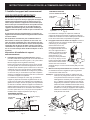
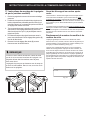
3. Anti-Tip Bracket Installation
Instructions
Important Safety Warning
To reduce the risk of tipping of the range, the range should
be secured to the oor by properly installed anti-tip bracket
and screws packed with the range. Failure to install the
anti-tip bracket will allow the range to tip over if excessive
weight is placed on an open door or if a child climbs upon
it. Serious injury might result from spilled hot liquids or from
the range itself.
If range is ever moved to a dierent location, the anti-tip
brackets must also be moved and installed with the range.
Instructions are provided for installation in wood or cement
fastened to either the oor or wall. When installed to the
wall, make sure that screws completely penetrate dry wall
and are secured in wood or metal. When fastening to the
oor or wall, be sure that screws do not penetrate electrical
wiring or plumbing.
A. Locate the Bracket Using the Template - (Bracket may be
located on either the left or right side of the range. Use
the information below to locate the bracket if template is
not available). Mark the oor or wall where left or right
side of the range will be located. If rear of range is against
the wall or no further than 1-1/4" (32 mm) from wall when
installed, you may use the wall or oor mount method. If
molding is installed and does not allow the bracket to t
ush against the wall, remove molding or mount bracket
to the oor. For wall mount, locate the bracket by placing
the back edge of the template against the rear wall and
the side edge of template on the mark made referencing
the side of the range. Place bracket on top of template
and mark location of the screw holes in wall. If rear of
range is further than 1-1/4" (32 mm) from the wall when
installed, attach bracket to the oor.
(31.75mm)
(31.75mm)
Fig. 4
Fig. 5
Fig. 6
Fig. 7
(17 mm)

6
30” GAS FRONT CONTROL FREESTANDING INSTALLATION INSTRUCTIONS
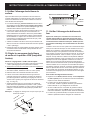
Fig. 9
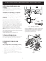
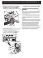
Be sure to stabilize the gas pressure regulator before
tightening ANY ttings to the pressure regulator. Do
not allow pressure regulator to turn on pipe when
tightening ttings (Refer to Fig. 9).
Fig. 8 - gas supply connections
Flare
union
adaptor
Flare
union
adaptor
Flexible appliance
conduit
Manual
shut-o
valve
Pressure
regulator
4. Provide an adequate gas
supply.
Please note: Operation at elevations above 2000 ft.,
appliance rating shall be reduced at the rate of 4 percent
for each 1000 ft. above sea level.
This appliance is pre-set to operate on 4” natural gas
manifold pressure. A convertible pressure regulator is
connected to the manifold and MUST be connected
in series with the gas supply line. If the LP/Propane
conversion kit has been used, follow instructions provided
with the kit for converting the pressure regulator to LP/
Propane use.
Care must be taken during installation of range not to
obstruct the ow of combustion and ventilation air.
For proper operation, the maximum inlet pressure to the
regulator should be no more than 14 inches of water
column pressure. The inlet pressure to the regulator must
be at least 1 inch greater than regulator manifold pressure.
Example: If regulator is set for natural gas 4 inch manifold
pressure, inlet pressure must be at least 5 inches; if
regulator has been converted for LP/Propane gas 10
inch manifold pressure, inlet pressure must be at least 11
inches.
Leak testing of the appliance shall be conducted according
to the instructions in step 4g.
The gas supply line should be 1/2” or 3/4” I.D.
5. Seal wall openings.
Seal any openings in the wall behind the range and in the
oor under the range after gas supply line is installed.
6. Connect range to gas
supply.
Note: To prevent leaks use pipe joint sealant on all male
(outside) pipe threads. Do not allow gas pressure reg-
ulator to turn on pipe when tightening ttings.
a. Install an external manual gas shut-o valve to gas
supply line in an accessible location outside of range.
Be sure you know where and how to shut o the gas
supply to the range (See Fig. 8).
b. Install 1/2” are union adapter to gas pressure
regulator using no more than 15ft./lbs. of torque (Refer
to Fig. 8).

7
30” GAS FRONT CONTROL FREESTANDING INSTALLATION INSTRUCTIONS
Checking manifold gas pressure
Do not use ame to check for gas leaks.
Disconnect the range and its individual shut-o valve from
the gas supply piping system during any pressure testing
of that system at test pressures greater than 14” of water
column pressure (approximately 1/2” psig).
The appliance must be isolated from the gas supply
piping system by closing its individual manual shut-o
valve during any pressure testing of the gas supply piping
system at test pressures equal to or less than 14” of water
column pressure (approximately 1/2” psig).
If it should be necessary to check the manifold gas
pressure, connect manometer (water gauge) or other
pressure device to the top burner right rear orice. Using
a rubber hose with inside diameter of approximately 1/4,”
hold tubing down tight over orice. Turn burner valve on.
For an accurate pressure check have at least two (2)
other top burners burning. Be sure the gas supply (inlet)
pressure is at least one inch above specied range
manifold pressure. The gas supply pressure should never
be over 14” water column. When properly adjusted for
Natural Gas the manifold pressure is 4”. For LP/Propane
Gas the manifold pressure is 10”.
c. Tighten the gas supply tting and/or appliance conduit
to are union adaptor on the right side of the pressure
regulator (refer to Fig. 10) using NO MORE THAN
15ft./lbs. of torque. Be sure to stabilize the 1/2” are
union adapter with an adjustable wrench before
tightening the gas supply tting and/or appliance
conduit.
d. Install are union adapter to external manual shut-o
valve (See Fig. 8).
e. Attach exible appliance conduit to are union adaptor
on shut-o valve (See Fig. 8).
f. Make sure the service shut-o valve on pressure
regulator is set to the ON position (See Fig. 11).
g. Check for gas leaks. Turn the gas supply on to the
range and use a liquid leak detector at all joints and
conduits to check for leaks in the system.
Fig. 10
Fig. 11
Pressure
regulator
Service shut-o valve
(shown in ON position)

8
30” GAS FRONT CONTROL FREESTANDING INSTALLATION INSTRUCTIONS
Grounding instructions:
The power cord of this appliance is equipped with a
3-prong (grounding) plug which mates with a standard
3-prong grounding wall receptacle to minimize the
possibility of electric shock hazard from this appliance.
The customer should have the wall receptacle and circuit
checked by a qualied electrician to make sure the
receptacle is properly grounded and polarized.
Do not, under any
circumstances, cut,
remove or bypass the
grounding prong.
Preferred method
Grounding
type wall
receptacle
Power
supply
cord with
3-prong
grounding
plug
Fig. 12
7. Read the following
electrical connection details
before connecting electricity
to range.
Before servicing, disconnect electrical sup-
ply at circuit breaker, fuse or power cord.
Electric requirements:
A dedicated, properly grounded and polarized branch
circuit protected by a 15 amp. circuit breaker or time delay
fuse. See serial plate for proper voltage.
Extension cord precautions:
Because of potential safety hazards under certain
conditions, we strongly recommend against the use of
any extension cord. However, if you still choose to use an
extension cord, it is absolutely necessary that it be a UL
listed 3-wire grounding type appliance extension cord and
that the current carrying rating of the cord in amperes be
equivalent to or greater than the branch circuit rating. Such
extension cords are obtainable through your local service
organization.
Please read carefully! For personal safety,
this product must be properly grounded.
Do not, under any circumstances, cut or remove the third
(ground) prong from the power cord (See Fig. 12).
Where a standard two-prong wall receptacle is
encountered, it is the personal responsibility and obligation
of the customer to have it replaced with a properly ground-
ed three-prong wall receptacle.
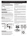
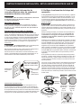
8. Check burner cap
placement.
It is very important to be sure that all surface burner caps
and burner grates are properly installed and in the correct
locations before operating the appliance. The cooktop is
not removeable. Do not attempt to remove or lift the cook-
top.
To prevent are-ups and avoid creation of
harmful by-products, do not use the cooktop without all
burner caps properly installed to insure proper ignition and
gas ame size.
Always keep the burner caps and burner heads in place
whenever the surface burners are in use. Do not allow
spills, food, cleaning agents or any other material to enter
the gas orice holder openings.
Check and be sure the size of each burner cap matches
the size of the burner head. Check and be sure that all
round style burner caps are correctly in place on round
burner heads.
Check and be sure that all oval style burner caps are cor-
rectly in place on oval burner heads (if equipped). Check
and be sure that all dual or twin style burner caps are cor-
rectly in place on dual or twin burner heads (if equipped).
On round style burners, the burner cap lip (See Fig. 13)
should t snug into the center of burner head and be level.
Refer to Figs. 14 & 15 for correct and incorrect burner cap
placement.
Once in place, you may check the t by gently sliding the
burner cap from side to side (Fig. 16) to be sure it is cen-
tered and rmly seated. Please note that the burner cap
should NOT move o the center of the burner head when
sliding from side to side.
Fig. 13
Correct burner
cap placement
Fig. 14
Incorrect burner
cap placement
Fig. 15
Fig. 16
Burner
cap
Burner
head
Ignitor
Orice

9
30” GAS FRONT CONTROL FREESTANDING INSTALLATION INSTRUCTIONS
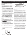
Fig. 17
Burner ame size
5/8”
Cooktop
Fig. 18
9. Check ignition of surface
burners.
Operation of electric igniters should be checked after
range and supply line connectors have been carefully
checked for leaks and range has been connected to
electric power.
a. To check for proper ignition, push in and turn a
surface burner knob counterclockwise to the LITE
position. You will hear the igniter sparking.
b. The surface burner should ignite when gas is available
to the burner. Purge air from supply lines by leaving
knob in the LITE position until burner ignites. Each
burner should light within four (4) seconds in normal
operation after air has been purged from supply lines.
c. Visually check that burner has a ame. Once the
burner ignites, the control knob should be turned out of
the LITE position.
d. Try each surface control knob separately until all
surface burners have been checked. Each burner
location is equipped with a separate electrode.
10. Adjust LOW setting of
surface burner valves (linear
ow).
Test to verify if LOW setting should be adjusted:
a. Push in and turn control to LITE until burner ignites.
b. Push in and quickly turn knob to lowest position.
c. If burner goes out, reset control to OFF.
d. Remove the surface burner control knob.
e. Insert a thin-bladed screwdriver into the hollow valve
stem and engage the slotted screw inside. Flame size
can be increased or decreased with the turn of the
screw (see Fig. 17 and Fig. 18).
DO NOT remove the adjustment screw
from the valve stem.
f. Adjust ame until you can quickly turn knob from
LITE to lowest position without extinguishing the
ame. Flame should be as small as possible without
extinguishing.
Note: Air mixture adjustments are not required on surface
burners.
11. Check ignition of oven
burners.
The operation of oven igniters should be checked after
range and supply line connectors have been carefully
checked for leaks and range has been connected to elec-
tric power. Be sure all packing materials and literature are
removed from oven.
The oven burner is equipped with an electric control sys-
tem as well as an electric oven burner igniter. If your model
is equipped with an upper oven burner, it will also have
an electric burner igniter. These control systems require
no adjustment. When the oven is set to operate, current
will ow to the igniter. It will “glow” similar to a light bulb.
When the igniter has reached a temperature sucient to
ignite gas, the electrically controlled oven valve will open
and ame will appear at the oven burner. There is a time
lapse from 30 to 60 seconds after the thermostat is turned
ON before the ame appears at the oven burner. When the
oven reaches the set temperature, the glowing igniter will
cycle o. The burner ame will turn o in 20 to 30 seconds
after the igniter turns o. To maintain any set oven
temperature, this cycle will continue as long as the oven
control is set to operate.
To check oven burner ignition:
a. Set oven to Bake at 300ºF. See User’s Manual for
operating instructions.
b. Within 60 seconds the oven burner should ignite.
Check for proper ame, and allow the burner to cycle
once. Reset control to OFF.
c. If your model is equipped with a waist-high broiler,
set oven to Broil. See User’s Manual for operating
instructions.
d. Within 60 seconds the broil burner should ignite.
Check for proper ame. Reset control to OFF.

10
30” GAS FRONT CONTROL FREESTANDING INSTALLATION INSTRUCTIONS
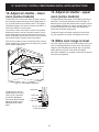
13. Adjust air shutter - upper
oven (some models)
The approximate ame length of the upper (broil) burner
should be 1 inch having a distinct inner, blue ame. To
determine if the upper broil burner ame is proper, set the
oven to Broil. If the ame is yellow, increase upper oven
air shutter opening size. If the ame is a distinct blue,
reduce the air shutter opening size.
To adjust the upper air shutter loosen lock screw (See
Fig. 20), reposition air shutter, and tighten lock screw.
14. Make sure range is level.
Level the range by placing a level horizontally on an oven
rack. Check diagonally from front to back, then level the
range by either adjusting the leveling legs or by placing
shims under the corners of the range as needed.
Note: After installation is complete, make sure all controls
are left in the o position.
12. Adjust air shutter - lower
oven (some models)
To determine if the oven burner ame is proper, remove
the oven bottom panel and lower burner bae (Refer to
Fig. 19) and set the oven to Bake at 300°F. The approx-
imate ame length of the lower oven burner should be 1
inch with a distinct inner blue ame.
To remove the lower oven bottom, remove oven bottom
hold down screws at rear of oven bottom panel. Pull up
at rear, disengage front of oven bottom from oven front
frame, and pull the oven bottom out of the oven. Remove
lower burner bae to observe oven burner ame.
If the ame is yellow in color, increase the lower oven air
shutter opening size. If the ame is a distinct blue, reduce
the air shutter opening size.
To adjust lower oven air
shutter loosen lock screw
(See Fig. 20), reposition
air shutter, and tighten
lock screw. When nished
adjusting replace burner
bae and oven bottom
panel.
Air shutter
Lock screw
Oven burner
Orice hood
Fig. 20 - typical oven
burner air shutter
Fig. 19 - oven burner locations
Upper oven burner
Upper oven burner
air shutter
Fig. 19 - oven burner locations
Upper oven burner
Upper oven burner
air shutter

11
30” GAS FRONT CONTROL FREESTANDING INSTALLATION INSTRUCTIONS
16. Care, Cleaning and
Maintenance
Refer to the Use & Care Manual for cleaning instructions.
If removing the range is necessary for cleaning or
maintenance, shut o gas supply. Disconnect the gas
and electrical supply. If the gas or electrical supply is
inaccessible, lift the range slightly at the front and pull out
away from the wall. Pull out only as far as necessary to
disconnect the gas and electrical supply. Finish removing
the range for servicing and cleaning. Reinstall in reverse
order making sure to level the range and check gas
connections for leaks. Be sure to read and follow step 1 for
proper Anti-tip installation.
Some models have a cold air intake vent at
the back of the unit. Do not cover this vent.
15. Install ller trim kit
Note: Installation of the ller trim kit is not required.
Disconnect electrical power to range before
beginning installation. Before servicing any part of the
appliance, make sure the appliance is o and the surfaces
are cool. Attempting to service the appliance while hot may
cause burns or other injury.
Filler Trim Attachment Instructions:
1. Remove the 7 screws on the vent trim on the back.
Range with ller trim installed.
2. Place the ller trim over the back by lining up the 7
screw holes of the ller trim with the vent trim and
tighten screws.
3. When ller trim is secured it will be ush with the top of
the range.

12
30” GAS FRONT CONTROL FREESTANDING INSTALLATION INSTRUCTIONS
Before You Call for Service
Read the "Before You Call" and operating instruction sections
in your Use & Care Manual. It may save you time and expense.
The list includes common occurrences that are not the result
of defective workmanship or materials in this appliance.
Refer to the warranty in your Use & Care Manual for our
toll-free service number and address. Please call or write if
you have inquiries about your range product and/or need to
order parts.
18. Model and Serial Number
Location
The serial plate is located on the right-hand surface of the
oven front frame at the storage or warmer drawer; or the
lower panel area.
When ordering parts for or making inquires about your range,
always be sure to include the model and serial numbers and
a lot number or letter from the serial plate on your range.
Your serial plate also tells you the Kilowatt rating (power
requirements) and Voltage ratings.
Serial plate is located on the lower right front frame
of the appliance. Alternate location may be under
cooktop.
Serial Plate Locations:
17. Door Handle Mounting In-
structions (some models)
1. Remove handles from carton and any other protective
packaging.
2. Position handle end caps over left and right pre-
installed shoulder bolts (A) that are fastened to the
door, ensuring the holes for the set screws are facing
down.
3. While holding handle rmly against door, loosely tighten
right Allen set screw (B) with supplied Allen wrench until
there is no gap between handle and door.
4. Still holding the handle rmly to the door, rmly tighten left
Allen set screw (B) with supplied Allen wrench.
5. Return to the right Allen set screw (B) and rmly tighten with
supplied Allen wrench.
All set screws should be tightened so the screw is
below the surface of the handle. The handle should be
drawn tight to the door with no gaps.
The door handle may loosen over time or if it was
installed improperly. If this happens, tighten the set
screws on the handles.
NOTE


14
INSTRUCTIONS D’INSTALLATION DE LA COMMANDE AVANT À GAZ DE 30 PO
Type de gaz approprié
Avant de commencer : Votre cuisinière est préréglée en usine
pour fonctionner au gaz naturel. Si une conversion au GPL est
nécessaire, communiquez avec votre fournisseur de GPL pour
obtenir de l’aide.
Il se peut qu’un nécessaire de conversion au GPL se trouve sur
le panneau du bas, à l’arrière de la cuisinière. Si ce nécessaire
de conversion n’est pas fourni, communiquez avec votre march-
and pour obtenir le nécessaire approprié.
809127208 Rev A (2020/06)
POUR VOTRE SÉCURITÉ :
— QUE FAIRE SI VOUS DÉTECTEZ UNE ODEUR
DE GAZ :
• Ne mettez pas d’appareil en marche.
• Ne touchez à aucun commutateur électrique;
ne vous servez pas du
téléphone de la maison.
• En utilisant le téléphone d’un voisin, appelez
immédiatement le fournisseur de gaz. Suivez
les directives données par votre fournisseur
de gaz.
• Si vous ne pouvez joindre votre fournisseur
de gaz, appelez les pompiers.
— L’installation et l’entretien de cet appareil
doivent être réalisés par un installateur qualié,
un technicien de service ou le fournisseur de
gaz.
• Assurez-vous d’enclencher le dispositif anti-renversement lorsque la
cuisinière est déplacée sur le plancher ou contre le mur.
• Ne faites pas fonctionner la cuisinière si le dispositif anti-
renversement n’est pas en place et enclenché.
• Le non-respect de ces instructions peut causer des blessures fatales
ou de graves brûlures aux enfants et aux adultes.
Pour vérier si le support anti-renversement est correctement installé,
attrapez le bord arrière de la cuisinière à deux mains. et essayez
doucement de faire basculer la cuisinière vers l’avant. Lorsque le
support est correctement installé, la cuisinière ne doit pas basculer
vers l’avant.
Reportez-vous aux instructions d’installation du support anti-
renversement fournies avec la cuisinière pour vous assurer que
l’installation est eectuée de façon appropriée.
Pied de mise
à niveau de la
cuisinière
Support anti-
renversement
• Un enfant ou un adulte peut faire basculer la
cuisinière et en décéder.
• Vériez que le dispositif anti-renversement a
été xé au plancher ou au mur.
Risque de basculement
L’INSTALLATION ET L’ENTRETIEN DOIVENT ÊTRE RÉALISÉS
PAR UN INSTALLATEUR QUALIFIÉ.
IMPORTANT : CONSERVEZ CES INSTRUCTIONS EN PRÉVISION D’UN USAGE ÉVENTUEL PAR
L’INSPECTEUR EN ÉLECTRICITÉ DE VOTRE LOCALITÉ. VEUILLEZ LIRE ET CONSERVER CES
INSTRUCTIONS POUR VOUS Y REPORTER ULTÉRIEUREMENT.
POUR VOTRE SÉCURITÉ :
Vous ne devez ni entreposer, ni utiliser
d’essence ou d’autres vapeurs ou liquides
inammables à proximité de cet appareil ou
de tout autre appareil électroménager.
INSTALLATION INSTRUCTIONS
FRONT CONTROL FREESTANDING GAS RANGE
Remarques importantes pour l’installateur
• Lisez toutes les instructions contenues dans ce guide avant de
procéder à l’installation de la cuisinière.
• Retirez tout le matériel d’emballage des compartiments du four
avant de connecter la cuisinière à l’alimentation en gaz et à
l’alimentation en électricité.
• Respectez tous les codes et tous les règlements.
• Assurez-vous de laisser ces instructions à l’utilisateur.
Remarque importante pour l’utilisateur
• Conservez ces instructions avec le guide d’utilisation et
d’entretien pour vous y reporter ultérieurement.
• Assurez-vous que votre cuisinière est installée et mise à la
terre de façon appropriée par un installateur qualié ou un
technicien de service.
• Assurez-vous que les revêtements muraux autour de la cui-
sinière peuvent résister à la chaleur générée par la cuisinière.
• Pour éliminer la nécessité d’atteindre au-dessus des éléments
de surface, l’espace de stockage de l’armoire au-dessus des
éléments doit être évité.

15
INSTRUCTIONS D’INSTALLATION DE LA COMMANDE AVANT À GAZ DE 30 PO
IMPORTANTES MESURES DE SÉCURITÉ
• L’installation de cette cuisinière doit être faite conformément
aux codes locaux ou, si ce type de code n’existe pas, au code
national sur le gaz combustible ANSI Z223.1 (dernière édition
si l’appareil est installé aux États-Unis).
• Si la cuisinière est installée dans une maison préfabriquée
(maison mobile), l’installation doit être conforme à la norme
Manufactured Home Construction and Safety Standard,
titre 24 CFR, partie 3280 (anciennement désignée comme la
Federal Standard for Mobile Home Construction and Safety,
titre 24, HUD [partie 280]) ou, si cette norme ne s’applique
pas, l’installation doit être conforme à la norme ANSI/NCSBCS
A225.1 de la Standard for Manufactured Home Installations,
ou aux codes locaux.
• La conception de cette cuisinière a été approuvée par CSA
Group. Comme dans le cas de tous les appareils fonctionnant
au gaz et produisant de la chaleur, il est nécessaire de suivre
certaines règles de sécurité. Vous les trouverez dans le Guide
d’utilisation et d’entretien. Lisez-les attentivement.
• Vériez que votre cuisinière est installée et mise à la terre
de façon appropriée par un installateur qualié ou un tech-
nicien de service.
• Cette cuisinière doit être mise à la terre conformément
aux codes locaux ou, en l’absence de tels codes, con-
formément au National Electrical Code ANSI/NFPA n
o
70
(dernière édition lorsque l’installation est faite aux États-
Unis). Reportez-vous aux instructions de mise à la terre se
trouvant à la page 8.
• Tous les matériaux utilisés dans la construction des armoires,
des enceintes et des supports entourant le produit doivent
avoir une température supérieure à 200 ° F (94 ° C).
• Avant d’installer la cuisinière dans un endroit recouvert
de linoléum ou de tout autre type de revêtement de sol
synthétique, assurez-vous que ce revêtement peut
supporter une chaleur se situant au moins à 50 ºC (90 ºF)
au-dessus de la température de la pièce sans qu’il ne
rétrécisse, ne gauchisse ou ne se décolore. N’installez pas
la cuisinière sur de la moquette, à moins que vous placiez une
plaque isolante en contreplaqué d’une épaisseur de 0,6 cm
(1/4 po) entre l’appareil et la moquette.
• Assurez-vous que le revêtement des murs qui se trouve
autour de la cuisinière peut supporter la chaleur produite
par celle-ci.
• N’obstruez pas le débit d’air ni au niveau de l’évent du
four, ni autour de sa base. Ne bloquez pas non plus le
panneau avant inférieur de la cuisinière. Évitez de touch-
er aux ouvertures de l’évent ou à la région située près des
surfaces, car celles-ci peuvent devenir très chaudes lorsque
le four fonctionne. Cette cuisinière nécessite de l’air frais pour
permettre une bonne combustion des brûleurs.
• Les rideaux d’air ou autres hottes de cuisinière en hauteur qui
projettent de l’air vers la cuisinière en contrebas ne doivent pas
être utilisés avec des cuisinières à gaz, sauf si la hotte et la
cuisinière ont été conçues, testées et répertoriées par un labo-
ratoire d’essais indépendant et peuvent fonctionner conjointe-
ment.
N’ESSAYEZ PAS DE FAIRE
FONCTIONNER LE FOUR À ALLUMAGE ÉLECTRIQUE
DURANT UNE PANNE D’ÉLECTRICITÉ. REMETTEZ TOUTES
LES COMMANDES DU FOUR À LA POSITION « OFF »
(ARRÊT) EN CAS DE PANNE D’ÉLECTRICITÉ.
L’allumeur électrique rallumera automatiquement le brûleur
du four lorsque l’électricité reviendra, si les commandes du ther-
mostat du four ont été laissées à « ON » (marche).
Lorsqu’une panne d’électricité survient durant l’utilisation, les
brûleurs de surface continueront de fonctionner.
Durant une panne d’électricité, les brûleurs de surface peuvent
être allumés au moyen d’une allumette. Pour ce faire, tenez une
allumette allumée près du brûleur, puis faites tourner lentement
le bouton à la position « LITE » (allumage). Faites preuve d’une
grande prudence lorsque vous allumez les brûleurs de cette
façon.
Ne laissez jamais un enfant seul ou
sans surveillance à proximité d’un appareil électroménager
en marche. Enseignez aux enfants la manière d’utiliser les
appareils électroménagers de façon appropriée et sécuritaire. Ne
laissez jamais la porte du four ouverte lorsque celui-ci est laissé
sans surveillance.
Grimper, s’appuyer ou s’asseoir sur
les portes ou les tiroirs de la cuisinière peut causer des bles-
sures graves aux personnes ainsi que des dommages
à la cuisinière.
• Ne rangez pas d’articles pouvant intéresser les enfants
dans les armoires se situant au-dessus de la cuisinière.
En voulant atteindre ces articles, les enfants risqueraient de se
brûler gravement.
• Pour éliminer le besoin d’avoir à se pencher au-dessus
des brûleurs de surface, vous devriez éviter de ranger des
articles dans les armoires situées au-dessus des brûleurs.
• Réglez la amme du brûleur de surface pour qu’elle ne dé-
passe pas du bord de l’ustensile de cuisson. Les ammes
excessives sont dangereuses.
• N’utilisez pas le four comme espace de rangement. Cela
pourrait créer une situation potentiellement dangereuse.
• N’utilisez jamais votre cuisinière pour réchauer ou
chauer une pièce. Une utilisation prolongée de la cuisinière
sans aération adéquate peut s’avérer dangereuse.
• N’entreposez pas et n’utilisez pas d’essence ni d’autres
liquides et vapeurs inammables près de la cuisinière ou
de tout autre appareil électroménager. Cela pourrait causer
des explosions ou des incendies.
• Remettez toutes les commandes à la position « OFF »
(arrêt) après avoir utilisé la fonction de programmation de
la minuterie.
• Contrairement à celle de certaines cuisinières, la table de
cuisson n’est pas amovible. Ne tentez pas de retirer cette table
de cuisson.

16
INSTRUCTIONS D’INSTALLATION DE LA COMMANDE AVANT À GAZ DE 30 PO
1. Dégagements et dimensions
a. Veillez à créer un dégagement susant entre la cuisinière et les surfaces combustibles adjacentes.
b. Emplacement – Vériez l’emplacement où sera installée la cuisinière. Conrmez la présence d’une source appropriée
d’électricité et de gaz ainsi que la stabilité du plancher.
c. Les dimensions données sur l’image doivent être respectées. Les dimensions données procurent un dégagement minimal.
La surface qui supportera l’appareil doit être solide et de niveau.
12.7cm
76.2cm Minimum*
.
91.4 cm
45.7 cm
33 cm
76.2 cm
Minimum
76.2 cm
Minimum
Vue de
face
Vue de
côté
Installation typique d'une armoire
Minimum au mur
de chaque côté
de la plage au-dessus de
91.4cm de hauteur
Minimum aux
armoires de
chaque côté
de la
cuisinière
Profondeur maxi-
male pour les
armoires au-dessus
de la cuisinière.
63.5 cm
Maximum
0 cm espace sous le plan de cuisson et à
l'arrière de la cuisinière
* AU MOINS 762 mm (30 po) DE DÉGAGEMENT ENTRE LE HAUT
DE LA SURFACE DE CUISSON ET LE BAS D’UNE ARMOIRE EN
BOIS OU EN MÉTAL NON PROTÉGÉE; OU AU MOINS 610 mm (24
po) LORSQUE LE BAS DE L’ARMOIRE EN BOIS OU EN MÉTAL
EST PROTÉGÉ PAR UN CELLODERME IGNIFUGE D’AU MOINS 6
mm (1/4 po) COMPORTANT UNE FEUILLE D’ACIER Nº 28, D’ACIER
INOXYDABLE D’AU MOINS 0,4 mm (0,015 po), D’ALUMINIUM D’AU
MOINS 0,6 mm (0,024 po) OU DE CUIVRE D’AU MOINS 0,5 mm
(0,020 po). 0 mm (0 po) CORRESPOND AU DÉGAGEMENT MINIMAL
POUR L’ARRIÈRE DE LA CUISINIÈRE. RESPECTEZ TOUTES LES
EXIGENCES CI-DESSUS RELATIVES AUX DIMENSIONS POUR
ÉVITER DES DOMMAGES À LA PROPRIÉTÉ, DES RISQUES
D’INCENDIE ET DES DÉCOUPES DE COMPTOIR ET D’ARMOIRE
INCORRECTES.
POUR ÉLIMINER LES RISQUES DE BRÛLURE OU D’INCENDIE
QUI PEUVENT SURVENIR EN VOUS PENCHANT AU-DESSUS
D’UN ÉLÉMENT DE SURFACE CHAUD, VOUS DEVRIEZ ÉVITER
DE RANGER DES ARTICLES DANS LES ARMOIRES AU-DESSUS
DE LA CUISINIÈRE. SI VOUS UTILISEZ DES ARMOIRES SITUÉES
AU-DESSUS DE LA CUISINIÈRE POUR LE RANGEMENT, VOUS
POUVEZ RÉDUIRE LES RISQUES D’ACCIDENT EN INSTALLANT
UNE HOTTE QUI DÉPASSE D’AU MOINS 127 mm (5 po) À
L’HORIZONTALE EN DESSOUS DES ARMOIRES.
N’ESSAYEZ PAS DE FAIRE
FONCTIONNER LE FOUR À ALLUMAGE ÉLECTRIQUE DURANT
UNE PANNE D’ÉLECTRICITÉ. REMETTEZ TOUTES LES
COMMANDES DU FOUR À LA POSITION « OFF » (ARRÊT) EN CAS
DE PANNE D’ÉLECTRICITÉ.
L’allumeur électrique rallumera automatiquement le brûleur du four
lorsque l’électricité reviendra, si les commandes du thermostat du four
ont été laissées à « ON » (marche).
75.9 cm
Maximum
93.0 cm
± 0.6 cm
67.9 cm
119.4 cm
Porte ouverte
Fig.1
Fig.2
Mur
ou
rmoire
Mur
ou
armoire
SOL
Emplacement du gaz
Espace
ouvert pour
le gaz
Cet espace
doit
rester dégagé
20.3 cm
30.6 cm
61.0 cm
57.5 cm
10 cm
Fig.3
16.5
cm
11 cm

17
INSTRUCTIONS D’INSTALLATION DE LA COMMANDE AVANT À GAZ DE 30 PO
2. Outils nécessaires
(Portez des lunettes de sécurité lorsque vous utilisez les outils) :
Pour l’ajustement des pieds de mise à niveau et l’installation
du support anti-renversement :
• Clé à molette ou pince multiprise ordinaire (Fig. a)
• Tournevis à douille de 5/16 po ou tournevis à lame plate
(Fig. b)
• Perceuse électrique munie d’une mèche de 1/8 po
(si l’installation est faite dans le béton, utilisez une mèche
à maçonnerie de 3/16 po) (Fig. c)
• Niveau (Fig. d)
Pour le raccord d’alimentation en gaz :
• Clé à molette et clé à tuyau (Fig. a et e)
Pour le réglage de la amme du brûleur :
• Tournevis Phillips et petit tournevis à lame plate (Fig. f et g)
Matériel requis :
• Pâte à joint pour tuyau résistant au gaz propane/GPL (Fig. h)
• Robinet d’arrêt manuel sur la conduite d’alimentation en gaz
(Fig. i)
• Conduite exible neuve en métal pour appareil électroménager
(1,3 cm [1/2 po] de NPT x 1,9 cm [3/4 po] ou 1,3 cm [1/2 po]
de diam. int.) approuvée par CSA International Étant donné
que les tuyaux rigides empêchent la cuisinière de bouger,
nous recommandons l’utilisation d’une conduite exible neuve
(mesurant de 121,9 cm à 152,4 cm [4 pi à 5 pi]) pour chaque
nouvelle installation ou réinstallation (Fig. j).
• Utilisez des raccords-unions évasés neufs
(1/2 po de NPT x 3/4 po ou 1/2 po de DI) (Fig. k).
Matériel fourni avec l’appareil :
• Gabarit pour support anti-renversement (Fig. l)
• Support anti-renversement avec deux vis de montage (Fig. m)
Outils
Fig. f
Matériel
PÂTE À
JOINT
Fig. h
Fig. i
Fig. j
Fig. k
Fig. d
Fig. c
Fig. g
Fig. b
Fig. a
Fig. e
SUPPORT ANTI-
RENVERSEMENT
GABARIT
SUPPORT ANTI-
RENVERSEMENT
SUPPORT ANTI-
RENVERSEMENT
Fig. l
Fig. m
Matériel fourni avec l’appareil
Instructions particulières pour les appareils installés dans l’État
du Massachusetts :
Cet appareil ne peut être installé dans l’État du Massachusetts
que par un plombier ou un monteur d’installations au gaz qualié
de cet État. Si vous utilisez un raccord de gaz exible, celui-ci
ne doit pas excéder 0,91 m (3 pi) de longueur. Un robinet de gaz
manuel en « T » doit être installé à la conduite de gaz qui est
branchée à cet appareil.
Lorsqu’une panne d’électricité survient durant l’utilisation, les brûleurs
de surface continueront de fonctionner.
Durant une panne d’électricité, les brûleurs de surface peuvent être
allumés au moyen d’une allumette. Pour ce faire, tenez une allumette
allumée près du brûleur, puis faites tourner lentement le bouton à la
position « LITE » (allumage). Faites preuve d’une grande prudence
lorsque vous allumez les brûleurs de cette façon.

18
INSTRUCTIONS D’INSTALLATION DE LA COMMANDE AVANT À GAZ DE 30 PO
3. Installer le support anti-renversement
AVIS DE SÉCURITÉ IMPORTANT!
An de réduire les risques de renversement, la cuisinière
doit être xée au plancher de façon appropriée au moyen du
support anti-renversement et des vis fournis avec la cui-
sinière. Ne pas installer le support anti-renversement peut
faire en sorte que la cuisinière bascule si un poids excessif
est placé sur la porte ouverte ou si un enfant grimpe sur
l’appareil. Des blessures graves peuvent être causées par
le renversement de liquides chauds ou par la cuisinière elle-
même.
Si vous devez changer l’emplacement de la cuisinière, les
supports anti-renversement doivent également être installés
au nouvel endroit.
Des instructions sont fournies pour l’installation dans le
bois ou dans le ciment, sur le plancher ou sur le mur. Lor-
sque vous faites l’installation sur le mur, assurez-vous que
les vis sont bien enfoncées dans la cloison sèche et qu’elles
sont xées dans du bois ou du métal. Lorsque vous faites
l’installation sur le plancher ou sur le mur, assurez-vous que
les vis ne s’enfoncent pas dans des ls électriques ou de la
tuyauterie.
Instructions d’installation du support
anti-renversement
a. Installation du support à l’aide du gabarit (le support
peut être installé sur le côté gauche ou sur le côté droit de la
cuisinière. Reportez-vous aux Figures 4, 5 et 7 pour l’instal-
lation du support si aucun gabarit n’est fourni).
Faites une marque sur le plancher ou sur le mur à l’endroit
où le côté gauche ou le côté droit de l’appareil se trouvera.
Si l’arrière de la cuisinière repose contre le mur ou se trouve
à moins de 3,2 cm (1-1/4 po) de celui-ci une fois installée,
vous pouvez utiliser la méthode de montage sur le plancher
ou sur le mur. S’il y a une moulure et que celle-ci empêche
d’appuyer complètement le support contre le mur, enlevez-la
ou montez le support sur le plancher.
Pour eectuer le montage sur le mur (Fig. 4), installez le
support en plaçant le bord arrière du gabarit contre le mur
qui se trouve à l’arrière de la cuisinière et le bord latéral du
gabarit sur la marque servant de repère pour l’emplacement
du côté de la cuisinière. Placez le support sur le dessus du
gabarit et faites des marques sur le mur pour indiquer à quel
endroit seront insérées les vis. Si l’arrière de la cuisinière
se trouve à plus de 3,2 cm (1-1/4 po) du mur lorsqu’elle est
installée, xez le support au plancher (voir Fig. 5).
SUPPORT ANTI-
RENVERSEMENT
Pour eectuer le montage sur le plancher, installez le
support en plaçant le bord arrière du gabarit à l’endroit où
l’arrière de la cuisinière se trouvera. Marquez les endroits où
les vis seront enfoncées, tel qu’illustré sur le gabarit.
b. Perçage d’avant-trous et xation du support - Percez un
avant-trou de 0,3 cm (1/8 po) à l’endroit où les vis seront
insérées (Fig. 6). Si le support
doit être monté sur le mur,
percez les avant-trous dans
un angle descendant d’environ
20º. Si le support doit être in-
stallé sur un plancher en béton
ou en céramique, percez des
avant-trous de 0,5 cm
(3/16 po) et d’une profondeur
de 4,5 cm (1-3/4 po). Les vis
fournies peuvent être utilisées
dans le bois ou dans le béton.
Servez-vous d’un tournevis à
douille de 5/16 po ou d’un tournevis à lame plate pour viser
le support.
c. Mise à niveau et positionnement de la cuisinière - Mettez
la cuisinière de niveau en réglant les quatre (4) pieds de
mise à niveau à l’aide d’une clé.
Remarque : Il est nécessaire de laisser un espace libre d’au
moins 0,3 cm (1/8 po) entre le bas de la cuisinière
et les pieds de mise à niveau pour le support.
Faites glisser la cuisinière pour la remettre en place
(Fig. 7). Retirez le panneau inférieur ou le tiroir de
rangement pour vérier si le pied de mise à niveau
arrière est inséré et solidement xé à l’aide du sup-
port. Dans le cas des modèles comportant un tiroir
chauant ou un tiroir-gril, agrippez le bord supérieur
arrière de la cuisinière et, avec précaution, tentez
de la pencher vers l’avant.
Fig. 4
Fig. 6
Fig. 5
1,7 cm
(
11
/
16
po)
Côté de
la cuisinière
Glissez la
cuisinère
en place
SUPPORT ANTI-
RENVERSEMENT
Fig. 7
FIXATION DU SUPPORT
(SUR LE PLANCHER OU SUR LE MUR)
Pied de mise
à niveau
Arrière
de la
cuisinière
3,2 cm (1-1/4 po)
max.
Fixation sur
le mur
Montant
Support anti-renversement
Fixation sur
le plancher
Plus de
3,2 cm
(1-1/4 po)
FIXATION DU SUPPORT
(SUR LE PLANCHER SEULEMENT)
Mur
Fixation sur
le plancher
Pied de mise
à niveau
Arrière
de la
cuisinière
Support anti-renversement

19
INSTRUCTIONS D’INSTALLATION DE LA COMMANDE AVANT À GAZ DE 30 PO
6. Raccorder la cuisinière à la conduite
d’alimentation en gaz
Remarque : Pour éviter les fuites, utilisez de la pâte à joint
pour tuyau sur tous les raccords de tuyau de type mâle (vers
l’extérieur). Empêchez le détendeur de gaz de s’ouvrir lorsque
vous eectuez le serrage des raccords.
a. Installez un robinet d’arrêt manuel externe sur la conduite
d’alimentation en gaz dans un endroit accessible situé à l’ex-
térieur de la cuisinière. Assurez-vous de connaître l’endroit où
se trouve le robinet d’arrêt ainsi que la façon d’arrêter l’alimen-
tation en gaz de la cuisinière (voir Fig. 8).
b. Installez un adaptateur à raccord-union de 1,3 cm (1/2 po) sur
le détendeur sans serrer à plus de 15 pi/lb (voir Fig. 8).
4. Prévoir une alimentation en gaz
adaptée
Remarque : Si l’altitude est supérieure à 610 m (2 000 pi), les
caractéristiques nominales de l’appareil doivent être réduites de
4 % pour chaque tranche de 305 m (1 000 pi) d’altitude au-des-
sus du niveau de la mer.
Cette cuisinière est préréglée pour fonctionner au moyen d’une
pression au collecteur de 10,2 cm (4 po). Un détendeur convert-
ible est raccordé au collecteur et DOIT être branché en série
avec la conduite d’alimentation en gaz. Si vous utilisez le néces-
saire de conversion au gaz propane/GPL, suivez les instructions
fournies dans ce nécessaire pour faire la conversion du déten-
deur.
Lors de l’installation de la cuisinière, il est important de s’assurer
que le débit d’air nécessaire à la combustion et à la ventilation
n’est pas obstrué.
Pour assurer le bon fonctionnement de la cuisinière, la pres-
sion d’admission maximale allant vers le détendeur ne doit pas
dépasser 35,6 cm (14 po) par rapport à la colonne d’eau. La
pression d’admission allant vers le détendeur doit être supérieure
d’au moins 2,5 cm (1 po) à la pression au collecteur du déten-
deur.
Exemple : Si le détendeur est réglé à une pression au collecteur
de 10,2 cm (4 po) pour le gaz naturel, la pression d’admission
doit être d’au moins 12,7 cm (5 po); si le détendeur a été converti
au gaz propane/GPL et est réglé à une pression au collecteur
de 25,4 cm (10 po), la pression d’admission doit être d’au moins
27,9 cm (11 po).
Veuillez procéder à la détection des fuites en suivant les instruc-
tions de l’étape 4g.
La conduite d’alimentation en gaz doit être d’un diamètre intérieur
de 1,3 cm (1/2 po) ou de 1,9 cm (3/4 po).
5. Boucher les ouvertures qui se trouvent
dans le mur
Après avoir installé la conduite d’alimentation en gaz, bouchez
toutes les ouvertures qui se trouvent dans le mur situé derrière la
cuisinière ainsi que ceux se trouvant dans la partie du plancher
située sous la cuisinière.
Fig. 8 - Branchement de l’alimentation
Veillez à stabiliser le côté gauche du détendeur de gaz
avant de serrer TOUS les autres raccords qui lui sont
rattachés. Empêchez le détendeur de s’ouvrir lorsque vous
eectuez le serrage des raccords (voir Fig. 9).
Détendeur
Conduit exible pour
électroménager
Adaptateur
à raccord-
union
Adaptateur
à raccord-
union
Robinet
d’arrêt
manuel
MARCHE
ARRÊT
Fig. 9

20
INSTRUCTIONS D’INSTALLATION DE LA COMMANDE AVANT À GAZ DE 30 PO
Vérier la pression de gaz au collecteur
N’utilisez pas de amme pour détecter
les fuites de gaz.
Débranchez la cuisinière et son robinet d’arrêt de la canalisation
de gaz si la vérication de la pression de l’alimentation en gaz
indique une pression qui dépasse 35,6 cm (14 po) à la colonne
d’eau, soit environ 3,54 kPa (1/2 lb/po
2
).
L’appareil doit être isolé de la canalisation de gaz en fermant son
robinet d’arrêt manuel si la vérication de la pression de la canali-
sation de gaz indique une pression égale ou inférieure à 35,6 cm
(14 po) à la colonne d’eau, soit environ 3,54 kPa
(1/2 lb/po²).
S’il s’avère nécessaire de vérier la pression de gaz au collec-
teur, branchez un manomètre (hydromètre) ou un autre appareil
de vérication de pression au gicleur du brûleur de surface
arrière droit. Tenez un tuyau en caoutchouc d’environ 0,6 cm
(1/4 po) de diamètre intérieur relié à l’appareil de vérication,
bien serré contre le gicleur. Ouvrez la soupape du brûleur.
Pour obtenir une vérication précise de la pression, faites
fonctionner au moins deux (2) autres brûleurs de surface pendant
la vérication. Assurez-vous que la pression d’alimentation en
gaz (pression d’admission) est supérieure d’au moins 2,5 cm
(1 po) à la pression du collecteur. La pression de l’alimentation
en gaz ne doit jamais être supérieure à 35,6 cm (14 po) à la
colonne d’eau. La pression au collecteur est de 10,2 cm (4 po)
lorsque celle-ci est ajustée de façon appropriée pour le gaz
naturel. Pour le gaz propane/GPL, la pression au collecteur doit
être de 25,4 cm (10 po).
c. Serrez le raccord d’alimentation en gaz ou la conduite de
l’appareil en le branchant à l’adaptateur de raccord-union
qui se trouve du côté droit du détendeur (voir Fig. 10) SANS
SERRER À PLUS DE 15 pi/lb. Veillez à stabiliser le raccord-
union évasé de 1,3 cm (1/2 po) au moyen d’une clé à molette
avant d’eectuer le serrage des raccords de l’alimentation en
gaz ou de la conduite de l’appareil.
d. Raccordez l’adapteur de raccord-union au robinet d’arrêt
manuel externe (voir Fig. 8).
e. Fixez la conduite de l’appareil à l’adaptateur de raccord-union
raccordé au robinet d’arrêt (voir Fig. 8).
f. Vériez que le robinet d’arrêt d’entretien qui se trouve sur
le détendeur est bien en position « ON » (marche)
(voir Fig. 11).
g. Vériez s’il y a des fuites. Ouvrez l’alimentation en gaz de la
cuisinière et servez-vous d’un détecteur de fuite de liquide
au niveau de tous les joints et de toutes les conduites pour
vérier s’il y a des fuites dans le système.
Fig. 11
Détendeur
Robinet d’arrêt d’entretien
(montre en position ON)
La page est en cours de chargement...
La page est en cours de chargement...
La page est en cours de chargement...
La page est en cours de chargement...
La page est en cours de chargement...
La page est en cours de chargement...
La page est en cours de chargement...
La page est en cours de chargement...
La page est en cours de chargement...
La page est en cours de chargement...
La page est en cours de chargement...
La page est en cours de chargement...
La page est en cours de chargement...
La page est en cours de chargement...
La page est en cours de chargement...
La page est en cours de chargement...
La page est en cours de chargement...
La page est en cours de chargement...
La page est en cours de chargement...
La page est en cours de chargement...
-
 1
1
-
 2
2
-
 3
3
-
 4
4
-
 5
5
-
 6
6
-
 7
7
-
 8
8
-
 9
9
-
 10
10
-
 11
11
-
 12
12
-
 13
13
-
 14
14
-
 15
15
-
 16
16
-
 17
17
-
 18
18
-
 19
19
-
 20
20
-
 21
21
-
 22
22
-
 23
23
-
 24
24
-
 25
25
-
 26
26
-
 27
27
-
 28
28
-
 29
29
-
 30
30
-
 31
31
-
 32
32
-
 33
33
-
 34
34
-
 35
35
-
 36
36
-
 37
37
-
 38
38
-
 39
39
-
 40
40


Frigidaire PCFG3078AF Guide d'installation
- Catégorie
- Micro-ondes
- Taper
- Guide d'installation
