Bertazzoni MAST305GASXE Guide d'installation
- Catégorie
- Cuisinières
- Taper
- Guide d'installation

BERTAZZONI
INSTALLATION MANUAL
FREESTANDING GAS RANGES
3100290
WWW.BERTAZZONI.COM

2
/ Table of contents
TABLE OF CONTENTS
WARNINGS ___________________________________________________________________
DATA RATING LABEL ___________________________________________________________
BEFORE INSTALLATION ________________________________________________________
VENTILATION PREPARATION ____________________________________________________
SPECIFICATIONS ______________________________________________________________
CLEARENCE DIMENSIONS ______________________________________________________
INSTALLATION REQUIREMENTS _________________________________________________
Electrical ___________________________________________________________________
Gas ________________________________________________________________________
ELECTRICAL CONNECTION _____________________________________________________
WIRING DIAGRAM _____________________________________________________________
GAS CONNECTION _____________________________________________________________
Manual shut-off valve _________________________________________________________
Flexible connections __________________________________________________________
Pressure test-point stopper valve _______________________________________________
Pressure regulator ____________________________________________________________
INSTALLATION ________________________________________________________________
Unpackaging the range ________________________________________________________
Removing the oven door _______________________________________________________
Installing the legs _____________________________________________________________
Installing the worktop frontguard ________________________________________________
Installing the island trim _______________________________________________________
Installing backguard (optional) __________________________________________________
INSTALLING THE ANTI-TIP DEVICES ______________________________________________
Anti-tip brackets ______________________________________________________________
Anti-tilt chain ________________________________________________________________
GAS CONVERSION _____________________________________________________________
INSTALLATION CHECKLIST ______________________________________________________
FINAL PREPARATION ___________________________________________________________
BERTAZZONI SERVICE _________________________________________________________
4
6
6
7
7
9
10
10
10
10
11
12
12
12
12
13
14
14
14
15
15
16
16
17
17
17
18
22
22
23

3
/ Models
Models
MAST304GASXV
MAST304GASXVLP
MAST305GASBIE
MAST305GASNEE
MAST305GASXE
MAST305GASXELP
MAST365GASBIE
MAST365GASNEE
MAST365GASXE
MAST365GASXELP
MAST366GASXT
MAST366GASXTLP
MAST486GGASBIE
MAST486GGASNEE
MAST486GGASXE
MAST486GGASXELP
MAST486GGASXT
MAST486GGASXTLP
Models
PROF304GASART
PROF304GASBIT
PROF304GASGIT
PROF304GASNET
PROF304GASROT
PROF304GASXT
PROF304GASXTLP
PROF366GASART
PROF366GASBIT
PROF366GASGIT
PROF366GASNET
PROF366GASROT
PROF366GASXT
PROF366GASXTLP
PROF486GGASART
PROF486GGASBIT
PROF486GGASGIT
PROF486GGASNET
PROF486GGASROT
PROF486GGASXT
PROF486GGASXTLP

4
/ Warnings
WARNINGS
To ensure proper and safe operation, the applian-
ce must be properly installed and grounded by a
qualifi ed technician. DO NOT attempt to adjust,
repair, service, or replace any part of your ap-
pliance unless it is specifi cally recommended in
this manual. All other servicing should be referred
to a qualifi ed servicer. Have the installer show you
the location of the gas shutoff valve and how to
shut it off in an emergency. A certifi ed technician
is required for any adjustments or conversions to
Natural or LP gas.
FOR THE INSTALLER: Before installing the Ber-
tazzoni appliance, please read these instructions
carefully. This appliance shall be installed in ac-
cordance with the manufacturer’s installation in-
structions. Leave these instructions with the ow-
ner, who should save them for local inspector’s
use and for future reference. DO NOT remove
permanently affi xed labels, warnings, or plates
from product. This may void the warranty.
Installation must conform with all local codes. In
the absence of codes:
• United States: installation must conform with
the National Fuel Gas Code ANSI Z223.1
INFPA54
• Massachusetts: All gas products must be
installed by a “Massachusetts” licensed plum-
ber or gasfi tter. A “T” type handle manual valve
must be installed in the gas supply line to the
appliance.
• Canada: Installation must be in accordance
with the current CAN/CGA B149.1 & 2 Gas
Installation codes and/or local codes. Electri-
cal installation must be in accordance with the
current CSA C22.1 Canadian Electrical Codes
Part 1 and/or local codes.
This range is NOT designed for installation in
manufactured (mobile) homes or recreational
park trailers.
DO NOT install this range outdoors.
This appliance must be properly grounded.
Grounding reduces the risk of electric shock by
providing a safe pathway for electric current in the
event of a short circuit.
Warning!
To avoid risk of property damage, personal
injury or death; follow information in this ma-
nual exactly to prevent a fi re or explosion.
Warning!
To avoid risk of property damage, personal injury
or death; follow information in this manual exact-
ly to prevent a fi re or explosion. DO NOT store
or use gasoline or other fl ammable vapors and
liquids nearbythis or any appliance.
WHAT TO DO IF YOU SMELL GAS: Do not
light any appliance. Do not touch any electri-
cal switch. Do not use any phone in your buil-
ding. Immediately call your gas supplier from
a neighbor’s phone. Follow the gas supplier’s
instructions. If you cannot reach your gas
supplier, call the fi re department.
NOTE: Installation and service must be perfor-
med by a qualifi ed installer, service agency or the
gas supplier.
DANGER!!! ELECTRIC SHOCK HAZARD!!!
To avoid risk of electrical shock, personal injury
or death, verify that the appliance has been pro-
perly grounded in accordance with local codes or
in absence of codes, with the National Electrical
Code (NEC). ANSI/NFPA 70- latest edition.
DANGER!!! GAS LEAK HAZARD!!!
To avoid risk of personal injury or death, leak-te-
sting of the appliance must be conducted accor-
ding to the manufacturer’s instructions. Before
placing appliance in operation, always check for
gas leaks with water and soap solution.
DO NOT USE AN OPEN FLAME TO
CHECK FOR GAS LEAKS.
Warning - tipping hazard
Children and adults can tip over the range if it has
not been secured.This may lead to fatal injuries.
To reduce the risk of the appliance tipping, it must
be secured and connected using the anti-tip devi-
ce according to the installation instructions.

5
/ Warnings
Re-engage the anti-tip device if the range is
moved. Do not operate the range without te
anti-tipdevice in place and engaged. Do not
use the range if the anti-tip device has not been
properly installed and engaged. See installation
instructions for details.
Failure to observe the information con-
tained in the installation instructions can
lead to serious or fatal injuries for chil-
dren and adults.

6
/ Data rating label / Before installation
The data rating label shows the model and serial
number of the range. It is located under the con-
trol panel and in the last page of this manual.
• This appliance shall only be installed by an au-
thorized professional.
• This appliance shall be installed in accordance
with the manufacturer’s installation instructions.
• This appliance must be installed in accordance
with the norms & standards of the country whe-
re it will be installed.
• The installation of this appliance must conform
to local codes and ordinances. In the absence
of local codes, Installations must conforms to
American National Standards, National Fuel
Gas Code ANSI Z223.1 – latest edition/NFPA
54 or B149.1.
• The appliance, when installed, must be electri-
cally grounded in accordance with local codes
or, in the absence of local codes, with the Natio-
nal Electrical Code, ANSI/NFPA 70.
If local codes permit, a fl exible metal appliance
connection conduit with the new AGA or CGA cer-
tifi ed design, max. 5 feet (1,5 m) long, ½” I.D. is
recommended for connecting this appliance to the
gas supply line. Do not bend or damage the fl exi-
ble connector when moving the appliance.
This appliance must be used with the pressure
regulator provided.
The regulator shall be properly installed in order to
be accessible when the appliance is installed in its
fi nal location. The pressure regulator must be set
for the type of gas to be used. The pressure regu-
lator has ½” female pipe thread. The appropriate
fi tting must be determined based on the size of
your gas supply line, the fl exible metal connector
and the shutoff valve.
The appliance must be isolated from the gas sup-
ply piping system by closing its individual manual
shutoff valve during any pressure testing of the
gas supply piping system at test pressures equal
to or less than 1/2 PSI (13,8” w.c. or 3,5 kPa).
All opening and holes in the wall and fl oor, back
and under the appliance shall be sealed before
installation of the appliance.
A manual valve shall be installed in an accessible
location in the gas line external to the appliance
for the purpose of turning on or shutting off gas to
the appliance.
Type of gas
This range can be used with Natural or LP/Pro-
pane gas. The range is shipped from the factory
for use with the gas indicated on the rating label
positioned on the lower face of the control panel
and in the last page of this manual. A step by step
conversion procedure is also included in this ma-
nual and in each conversion kit.
Gas pressure
The maximum inlet gas supply pressure incoming
to the gas appliance pressure regulator is 1/2 PSI
(13,8’’ w.c. or 3,5 kPa). The minimum gas supply
pressure for checking the regulator setting shall
be at least 1“ w.c. (249 Pa) above the inlet speci-
fi ed manifold pressure to the appliance; this ope-
rating pressure is 4” w.c. (1.00 kPa) for Natural
Gas and 11” w.c. (2.75 kPa) for LP Gas.
Room ventilation
An exhaust fan may be used with the appliance;
in each case it shall be installed in conformity
with the appropriate national and local standards.
Exhaust hood operation may aff ect other vented
appliances; in each case it shall be installed in
conformity with the appropriate national and local
standards.
Warning
This appliance should not be installed with a
ventilation system that directs air in a downward
direction toward the range. This type of ventila-
tion system may cause ignition and combustion
problems with the appliance resulting in personal
injury, property damage, or unintended operation.
Ventilating systems that direct the air upwards do
not have any restriction.
Do not use aerosol sprays in the vicinity of
this appliance while it is in operation.
DATA RATING LABEL
BEFORE INSTALLATION

7
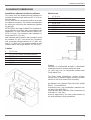
This range will best perform when installed with
Bertazzoni exhaust hoods. These hoods have
been designed to work in conjunction with the
Bertazzoni range and have the same fi nish for a
perfect look.
Before installation of the exhaust hood, consult lo-
cal or regional building and installation codes for
additional specifi c clearance requirements.
Refer to the range hood installation instructions
provided by the manufacturer for additional infor-
mation.
Select Hood and Blower Models:
• For wall installations, the hood should be equal
or larger width than the range. Where space
permits, a hood larger than the range may be
desirable for improved ventilation performance.
• For island installations, the hood width should
overhang the range by a minimum of 3” (76
mm) on each side.
Hood Placement:
• For best removal of smoke and odors, the
lower edge of the hood should be installed
between 25 1/2” (65 cm) and 31 1/2” (80 cm)
above the range cooking surface.
• If the hood contains any combustible materials
(i.e. a wood covering), it must be installed at a
minimum of 36” (914 mm) above the cooking
surface.
Consider Make-Up Air:
Due to the high volume of ventilation air, a sour-
ce of outside replacement air is recommended.
This is particularly important for tightly sealed
and insulated homes. A qualifi ed heating and
ventilating contractor should be consulted.
/ Ventilation preparation / Specifi cations
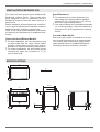
VENTILATION PREPARATION
SPECIFICATIONS
A
27''
/8
37''
1/2
MAX
1''
15/16
25''
/16
2''
1''
5/8
32''
3''
3/4
- 5''
1/2
5''
1''
5/8
1''
1/8
''
/
23''
7/8
3''
7/16
3 ''
11/16
2''
7/16
A
A
30’’ 36’’ 48’’

8
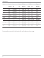
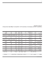
/ Specifi cations
Burner
Auxiliary
Semi-rapid
Rapid
Dual burner
MAIN oven
30’’/48’’
Broiler
30’’/48’’
Oven 36’’
Broiler 36’’
AUX. Oven
48’’
Injector
diam.[mm]
0.90
0.54
1.18
0.70
1.55
0.92
0.80+2.10
0.50+1.20
1.85
1.10
1.40
0.98
2.00
1.16
1.60
0.98
1.25
0.75
Gas
Type
NG
LP (Propane)
NG
LP (Propane)
NG
LP (Propane)
NG
LP (Propane)
NG
LP (Propane)
NG
LP (Propane)
NG
LP (Propane)
NG
LP (Propane)
NG
LP (Propane)
Pressure
[iwc]
4’’
10’’
4’’
10’’
4’’
10’’
4’’
10’’
4’’
10’’
4’’
10’’
4’’
10’’
4’’
10’’
4’’
10’’
Max Rate
[Btu/hr]
3,500
3,300
5,900
5,500
10,400
9,500
19,000
19,000
14,000
14,500
9,000
10,500
17,000
15,000
11,000
11,000
7,000
7,000
Min Rate
[Btu/hr]
900
900
1,500
1,500
2,500
2,500
1,300
1,300
3,500
3,500
only max
only max
4,100
4,100
only max
only max
2,400
2,400
[W]
1,025
967
1,729
1,611
3,047
2,783
5,567
5,567
4,102
4,248
2,637
3,076
4,981
4,395
3,223
3,223
2,051
2,051
[W]
264
264
439
439
732
732
381
381
1,025
1,025
only max
only max
1,201
1,201
only max
only max
703
703
By-pass
diam.[mm]
Regulated
0.29
Regulated
0.36
Regulated
0.47
Regulated
0.34/0.65
Regulated
0.60
No by-pass
No by-pass
Regulated
0.62
No by-pass
No by-pass
Regulated
0.49
See use and care manual for the layout of the surface burners of your range
B
urner In
j
ector
G
a
s
Pre
ss
ure Max Rate Min Rate
By
-pas
s

9
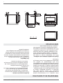
/ Clearence dimensions
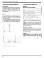
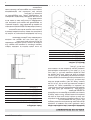
CLEARENCE DIMENSIONS
Installation adjacent to kitchen cabinets
This range may be installed directly adjacent to
existing countertop high cabinets (36” or 91.5 cm
from the fl oor).
For the best look, the worktop should be level with
the cabinet countertop. This can be accomplished
by raising the unit using the adjustment spindles
on the legs.
ATTENTION: the range CANNOT be installed di-
rectly adjacent to kitchen walls, tall cabinets, tall
appliances, or other vertical surfaces above 36”
(91.4 cm) high. The minimum side clearance in
such cases is 6” (15.2 cm).
Wall cabinets with minimum side clearance must
be installed 18” (45.7 cm) above the countertop
with countertop height between 35 ½” (90.2 cm)
and 37 ¼” (94.6 cm). The maximum depth of wall
cabinets above the range shall be 13” (33.0 cm).
Cabinet
Shaded area behind range indicates minimum
clearance to combustible surfaces, combustible
materials cannot be located within this area.
12” (305 mm) min. to combustible surface with
Flush Island Trim
For Flush Island installations, counter surface
should have a cantilever edge meeting the back
section of the Flush Island Trim accessory.
As defi ned in the “National Fuel Gas Code” (ANSI
Z223.1, Current Edition).
Clearances from non-combustible materials are
not part of the ANSI Z21.1
scope and are not certifi ed by CSA. Clearances of
less than 12” (305 mm)
must be approved by the local codes and/or by
the local authority having jurisdiction.
Metal hood
A
B
C
D
E
F
G
A
B
C
D
E
F
G
H
30’’ (76,2 cm)
36’’ (91,5 cm) hood with combustible materials
13’’ (33,0 cm)
18’’ (45,7 cm)
35’’ 1/2(90,2 cm) / 37”
1/4
(94,6 cm)
6’ (15,2 cm)
12”(30,50 cm)
30’’ (76,2 cm)
25 1/2’’(65 cm) and 31 1/2’’ (80 cm)
13’’ (33,0 cm)
18’’ (45,7 cm)
35’’ 1/2(90,2 cm) / 37”
1/4
(94,6 cm)
6’ (15,2 cm)
12”(30,50 cm)
1” 9/16(4 cm)

10
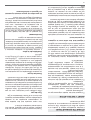
/ Installation requirements / Electrical connection
ELECTRICAL
A properly-grounded horizontally- mounted electri-
cal receptacle should be installed no higher than
3” (7.6 cm) above the fl oor, no less than 2” (5 cm)
and no more than 8” (20,3 cm) from the left side
(facing product).
Check all local code requirements.
GAS
An agency-approved, properly-sized manual
shut-off valve should be installed no higher than
3” (7.6 cm) above the fl oor and no less than 2” (5
cm) and no more than 8” (20.3 cm) from the right
side (facing product).
To connect gas between shut-off valve and regula-
tor, use agency-approved, properly sized fl exible
or rigid pipe. Check all local code requirements.
Warning!
ELECTRICAL SHOCK HAZARD
Disconnect electrical power at the circuit bre-
aker box or fuse box before installing the ap-
pliance.
Provide appropriate ground for the appliance.
Use copper conductors only.
Failure to follow these instructions could re-
sult in serious injury or death.
This unit is manufactured for a polarized, groun-
ded 120 volt/60 Hz, 16 amp system.
Electric power consumption is about 300 W for
30” and 36”, 1200W for 48”
The minimum of 102 VAC is required for proper
operation of gas ignition systems.
The circuit must be grounded and properly pola-
rized.
The unit is equipped with a SJT power cord and
a NEMA 5-15P plug. In case of replacement, the
power cord shall be replaced with one of the same
type, size and length.
Electrical grounding
This appliance is equipped with a three-prong
plug for your protection against shock hazard and
should be plugged directly into a properly groun-
ded socket. Do not cut or remove the grounding
prong from this plug.
Caution
Label all wires prior to disconnecting when
servicing controls. Wiring errors can cause
improper and dangerous operation.
Verify proper operation after servicing.
INSTALLATION REQUIREMENTS ELECTRICAL CONNECTION
installation area for the connection

11
/ Wiring diagram
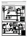
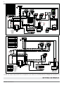
WIRING DIAGRAM
The electric wiring diagrams and schematics are attached behind the range, and should not be removed
except by a service technician, then replaced after service.
MV
1
2
3
4
P
2
P
1
P
3
P
4
COM
Comm.2+0
G
L
N
GV
M
Simb. Description
rRed
gr Green (earth)
v Violet
aOrange
n Black (line)
bi White (neutral)
COLOURS
Simb. Description
IGN Ignition Micro switches
INV Fan Oven Interlock
COM Oven Function Selector
G Spark Generator
ILF Oven lamp switch
KI Termal switch
LF Oven lamp
M Terminal Block
MV Fan motor
MVT Cooling fan motor
T-Z T-zero
LEGENDA
a
a
r
r
bi
m
n
bi
gv
bi
n
gv
MVT
KI
bi
n
J13
J1 J2 J3 J4 J5 J6
MAGNET UNITS &
TERMOCOUPLES
J12 J11J10 J9 J8 J7
T-Z
MV
IGN
INV
ILF
LF
LF
IGN
v
r
n
n
gr
gv
3071063
MV
1
2
3
4
P
2
P
1
P
3
P
4
COM
Comm.2+0
G
L
N
GV
M
Simb. Description
rRed
gr Green (earth)
bBlue
v Violet
aOrange
n Black (line)
bi White (neutral)
COLOURS
Simb. Description
IGN Ignition Micro switches
INV Fan Oven Interlock
COM Oven Function Selector
G Spark Generator
GE Griddle Thermostat
ILF Oven lamp switch
KI Termal switch
LF Oven lamp
M Terminal Block
MV Fan motor
MVT Cooling fan motor
RGR Griddle element
TSS Safety Thermostat
T-Z T-zero
LEGENDA
a
a
r
r
bi
n
bi
gv
bi
gv
bi
J13
J1 J2 J3 J4 J5 J6
MAGNET UNITS &
TERMOCOUPLES
J12 J11J10 J9 J8 J7
T-Z
MV
IGN
left
INV
ILF
left
LF
left
LF
left
IGN
v
r
n
n
gv
gv
RGR
TSS
1
2
ILF
right
LF
right
MVT
right
S
GE
IGN
right
KI
MVT
left
b
a
a
n
n
bi
bi
n
bi
bi
r
r
a
r
n
3071064

12
/ Gas connection
Warning!
DO NOT USE AN OPEN FLAME WHEN
CHECKING FOR LEAKS!
Leak testing of the appliance shall be conducted
according to the manufacturer’s instructions. Be-
fore placing the oven into operation, always check
for leaks with soapy water solution or other accep-
table method.
Check for gas leakage with soapy water solution or
other acceptable methods in all gas connections
installed between inlet gas pipe of the appliance,
gas regulator, till to the manual shut-off valve.
All gas connections must comply with national and
local codes. The gas supply line (service) must be
the same size or greater than the inlet line of the
appliance. This range uses a 1/2” NPT inlet (see
drawing below for details of gas connection). On
all pipe joints use appropriate sealant resistant to
gas to joint the adapter to range manifold use only
the blue gasket supplied.
If necessary, the appliance must be converted by
the dealer, by a factory-trained professional or by
a qualifi ed licensed plumber or gas service com-
pany.
Gas conversion is important for safe and eff ecti-
ve use of the appliance. It is the responsibility of
the dealer and the owner of the range to perform
the appropriate gas conversion following the di-
rections of the manufacturer.
THE GAS CONVERSION PROCEDURE IS
DESCRIBED IN THIS MANUAL AND IN THE
PACKAGE CONTAINING THE CONVERSION
NOZZLES SHIPPED WITH EVERY RANGE.
Please provide the service person with this ma-
nual before work is started on the range.
MANUAL SHUT-OFF VALVE
THIS VALVE IS NOT SHIPPED WITH THE AP-
PLIANC AND MUST BE SUPPLIED BY THE IN-
STALLER.
The manual shut-off valve must be installed in the
gas service line between the gas hook-up on the
wall and the appliance inlet, in a position where it
can be reached quickly in the event of an emer-
gency.
In Massachusetts: A ‘T’ handle type manual
gas valve must be installed in the gas supply line
to this appliance.
FLEXIBLE CONNECTIONS
In case of installation with fl exible couplings and/
or quick-disconnect fi ttings, the installer must use
a heavy-duty, AGA design-certifi ed commercial
fl exible connector of at least 1/2” (1.3 cm) ID NPT
(with suitable strain reliefs) in compliance with
ANSI Z21.41 and Z21.69 standards.
In Massachusetts: The unit must be installed
with a 36” (3-foot) long fl exible gas connector.
In Canada: use CAN 1-6.10-88 metal connec-
tors for gas appliances and CAN 1-6.9 M79 quick
disconnect device for use with gas fuel.
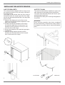
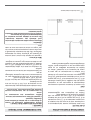
PRESSURE TEST-POINT STOPPER
VALVE
To avoid gas leaks, the pressure test-point stop-
per valve and gasket supplied with the range must
be installed on the gas fi tting at the back of the
range according to the diagram below.
GAS CONNECTION
GAS PIPE
BASKET
PRESSURE TEST-POINT
STOPPER
GAS CONNECTION ADAPTOR
1/2’’NPT WITH PRESSURE TEST
POINT 1/8’’ NPT (TO BE FIXED
TOWARD EXTERNAL SIDE OF
THE APPLIANCE)

13
/ Gas connection
PRESSURE REGULATOR
Since service pressure may fl uctuate with local
demand, every gas cooking appliance must be
equipped with a pressure regulator on the inco-
ming service line for safe and effi cient operation.
The pressure regulator shipped with the applian-
ce has two female threads ½” NPT. The regulator
shall be installed properly in order to be accessible
when the appliance is installed in its fi nal position.
Manifold pressure should be checked with a ma-
nometer and comply with the values indicated be-
low:
Natural gas 4.0” W.c.P.
LP/Propane 11.0” W.C.P.
Incoming line pressure upstream from the regu-
lator must be 1” W.c.P. higher than the manifold
pressure in order to check the regulator.
The regulator used on this range can withstand a
maximum input pressure of 1/2 PSI (13,8” w.c. or
3,5 kPa) If the line pressure exceeds that amount,
a stepdown regulator is required.
The appliance, its individual shut-off valve, and
the pressure regulator must be disconnected from
the gas line during any pressure testing of that sy-
stem at pressures in excess of 1/2 PSI (13,8” w.c.
or 3,5 kPa).
The individuaL manual shut-off valve must be in
the OFF position during any pressure testing of
the gas supply piping system at test pressures
equal to or less than 1/2 PSI (13,8” w.c. or 3,5
kPa).
Warning
Before carrying out any servicing operation di-
sconnect the appliance from gas and electric
supply and extra appliance from fi nal installation
place in order to have access to the appliance for
proper servicing intervention.

14
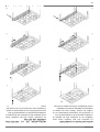
/ Installation
APPLIANCE INSTALLATION
Unpacking the range
• Remove all packing materials from the ship-
ping pallet but leave the adhesive-backed foam
layer over brushed-metal surfaces to protect it
from scratches until the range is installed in its
fi nalposition. Only the fi lm on the side panels
should be removed before inserting the range
between the cabinets.
• Examine the appliance after unpacking it. In the
event of transport damage, do not plug it. Take
pictures of the damage and report it immedia-
tely to the freight forwarder.
• Remove the oven door(s). This will reduce the
weight of the range.
• The grates, griddle plate, burner caps, and oven
racks should be removed to facilitate handling.
• Before moving the range, protect the fl oor to
prevent damage.
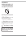
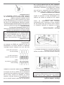
REMOVING THE OVEN DOOR
Prepare the door for removal. Flip up the locking
clamps on each door hinge. Slowly shut the door
until the protruding clamps stop the movement.
Pull oven door upwards and remove.
Do not lift or carry the oven door by its handle!
This may damage the hinges.
INSTALLATION
2
1
3

15
/ Installation
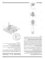
INSTALLING THE LEGS
Bertazzoni ranges must be used only with the legs
properly installed.
Four height-adjustable legs are supplied with the
range in the polysterene container situated over
the appliance.
Before installing the legs, position the appliance
near its fi nal location as the legs are not suitable
for moving the appliance over long distances.
After unpacking the range, raise it enough to in-
sert the legs in the appropriate receptacles situa-
ted on the lower part of the appliance. Lower the
range gently to keep any undue strain from legs
and mounting hardware. If possible use a pallet or
lift jack instead of tilting the unit.
Adjust leg height to the desired level by twisting
the inside portion of the leg assembly until the pro-
per height is reached. Check with a level that the
cooktop is perfectly level.
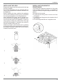
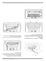
INSTALLING THE WORKTOP
FRONTGUARD
To increase the clearance between the front edge
of the worktop and the burners it is possible to
install the worktop frontguard shipped with the ap-
pliance.
To install the front guard,
• Locate the two fi xing holes on the end of the
frontguard
• Locate the two fi xing holes in the bottom side of
the worktop
• Fix the frontguard with the 2 supplied screw
1
2
3
4

16
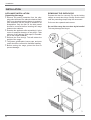
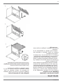
INSTALLING THE ISLAND TRIM
The island trim must be installed prior to operation
of the appliance for appropriate ventilation of the
oven compartment.
The island trim is only placed on the cooktop, re-
move all tape and packaging before installing it.
INSTALLING BACKGUARD (OPTIONAL)
The backguard must be installed prior to opera-
tion of the appliance for appropriate ventilation of
the oven compartment.
The backguard is an optional contact you dealer
for buying it.
/ Installation
1 1
2 2
3
3
4 4

17
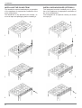
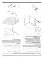
ANTI-TIP BRACKETS
The anti-tip bracket shipped with the range must
be properly secured to the rear wall as shown in
the picture below.
The height of the bracket from the fl oor must be
determined after the range legs have been adju-
sted to the desired height and after the range has
been levelled.
• Measure the distance from the fl oor to the
bottom of the anti-tip bracket receptacle on the
back of the appliance.
• Position the anti-tip brackets on the wall at
the desired height plus 1/8” (0.32 cm). The
brackets must be placed at 2”5/16 (6,0 cm)
from the side of the range.
• Secure the brackets to the wall with appropria-
te hardware.
• Slide the range against the wall until the
brackets are fully inserted into their recepta-
cles on the back of the range.
ANTI/TILT CHAIN
The anti-tilt chain shall be installed on right or left
side alternatively according below instructions.
The chain shall be hand pulled and fi xed to open
hook through closed ring.
Disengage the chain prior to moving the appliance
for service.
Attention:
Once servicing operation have been completed
the anti-tilt devices ( brackets and chain) shall be
re-engaged according above instruction/installa-
tions.
INSTALLING THE ANTI/TIP DEVICES
1
2
CLOSED RING OPEN HOCK
/ Installing the anti/tip devices

18
GAS CONVERSION
Warning!
Before carrying out this operation, disconnect the
appliance from gas and electricity.
Gas conversion shall be conducted by a fac-
tory-trained professional.
Call the customer service hotline to identify a fac-
tory-trained professional near your home.
The gas conversion procedure for this range in-
cludes 6 steps:
• Pressure regulator
• Surface burners
• Oven burner
• Broiler burner
• Visual checks prior to closure of oven bottom
panel
• Adjustment of minimum setting
The conversion is not completed if all 6 steps have
not been concluded properly.
Before performing the gas conversion, locate the
package containing the replacement nozzle ship-
ped with every range.
IMPORTANT: Each nozzle has a number indica-
ting its fl ow diameter printed on the body. Consult
the table number 1 for matching nozzles to bur-
ners.
Save the nozzles removed from the range for fu-
ture use.
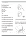
Step 1: pressure regulator
The pressure regulator supplied with the applian-
ce is a convertible type pressure regulator for use
with Natural Gas at a nominal outlet pressure of
4” w.c. or LP gas at a nominal outlet pressure of
11” w.c. and it is pre-arranged from the factory to
operate with one of these gas/pressure as indica-
ted in the labels affi xed on the appliance, package
and Instruction booklet.
To convert the regulator for use with the other gas:
Unscrew by hand the upper cap of the regula-
tor, remove the white plastic attachment from the
cap, reverse its direction and screw it again fi rm-
ly against the cap. The white plastic attachment
has arrows indicating the position for natural gas
(NAT) and LP gas (LP).
Screw by hand the metal cap in the original posi-
tion on the regulator.
Step 2: surface burners
To replace the nozzles of the surface burners, lift
up the burners and unscrew the nozzles shipped
with the range using a 7 mm (sochet wrench).
Replace nozzles using the conversion set sup-
plied with the range or by a Bertazzoni authori-
zed parts warehouse. Each nozzle has a number
indicating its fl ow diameter printed on the body.
Consult the table number 1 and matching nozzles
to burners.
/ Gas conversion
LP
NAT

19
DISEGNI
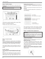
Step 3: oven burner (main or auxiliary)
To replace the nozzles of the main oven bur-
ner, start by removing the door and the bot-
tom panel of the oven.
Remove the screw located on the right side of the
burner and pull out the burner from its support.
ATTENTION: pay extra attention to avoid damage
to the igniter and thermocouple.
Unscrew the nozzle located inside the gas fi tting
using a 7 mm [ socket wrench].
Replace the nozzle as table number 1.
/ Gas conversion
1
2
3
4

20
Step 4: broiler burner
Remove the screw and pull out the burner from
its support.
ATTENTION: pay extra attention to avoid damage
to the igniter and thermocouple.
Unscrew the nozzle located inside the gas fi tting
using a 7 mm [socket wrench].
Replace the nozzle as table number 1.
Step 5: visual checks
Oven
Before reinstalling the bottom panel, the following
visual check must be performed to ensure that the
conversion has been carried out properly and wi-
thout damage to other components of the range.
Verify that the fl ame of the oven/broiler burner be
completely blue and with regular aspect as shown
below.
Surface burners
The burner fl ame color should be blue with no yel-
low on the tips. It is not uncommon to see orange
in the
fl ame color; this indicates the burning of airborne
impurities in the gas and will disappear with use.
With propane (LP) gas, slight yellow tips on the
primary icone are normal.
The fl ame should burn completely around the bur-
ner cap. If it doesn’t, check that the cap is posi-
tioned
correctly on the base and that the ports are not
blocked.
The fl ame should be stable with no excessive noi-
se or fl uttering.
After performing all these visual checks, reinstall
the bottom panel of the oven compartment and
proceed to setting the minimum for each burner.
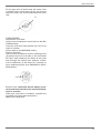
Step 6: minimum fl ame adjustment
WARNING!
These adjustments should be made only for use
of the appliance with natural gas. For use with li-
quid propane gas, the choke screw must be fully
turned in a clockwise direction.
SURFACE BURNERS
Light one burner at a time and set the knob to the
MINIMUM position (small fl ame).
Remove the knob.
The range is equipped with a safety valve. Using
a small-size slotted screwdriver, locate the choke
valve on the valve body and turn the choke screw
to the right or left until the burner fl ame is adjusted
to desired minimum.
Make sure that the fl ame does not go out when
switching quickly from the MAXIMUM to the MINI-
MUM position.
yellow fl ames:
further adjustment is required
yellow tips on outer cones:
normal for LP gas
soft blue fl ames:
normal for natural gas
/ Gas conversion
1
2
La page est en cours de chargement...
La page est en cours de chargement...
La page est en cours de chargement...
La page est en cours de chargement...
La page est en cours de chargement...
La page est en cours de chargement...
La page est en cours de chargement...
La page est en cours de chargement...
La page est en cours de chargement...
La page est en cours de chargement...
La page est en cours de chargement...
La page est en cours de chargement...
La page est en cours de chargement...
La page est en cours de chargement...
La page est en cours de chargement...
La page est en cours de chargement...
La page est en cours de chargement...
La page est en cours de chargement...
La page est en cours de chargement...
La page est en cours de chargement...
La page est en cours de chargement...
La page est en cours de chargement...
La page est en cours de chargement...
La page est en cours de chargement...
La page est en cours de chargement...
La page est en cours de chargement...
La page est en cours de chargement...
La page est en cours de chargement...
-
 1
1
-
 2
2
-
 3
3
-
 4
4
-
 5
5
-
 6
6
-
 7
7
-
 8
8
-
 9
9
-
 10
10
-
 11
11
-
 12
12
-
 13
13
-
 14
14
-
 15
15
-
 16
16
-
 17
17
-
 18
18
-
 19
19
-
 20
20
-
 21
21
-
 22
22
-
 23
23
-
 24
24
-
 25
25
-
 26
26
-
 27
27
-
 28
28
-
 29
29
-
 30
30
-
 31
31
-
 32
32
-
 33
33
-
 34
34
-
 35
35
-
 36
36
-
 37
37
-
 38
38
-
 39
39
-
 40
40
-
 41
41
-
 42
42
-
 43
43
-
 44
44
-
 45
45
-
 46
46
-
 47
47
-
 48
48


Bertazzoni MAST305GASXE Guide d'installation
- Catégorie
- Cuisinières
- Taper
- Guide d'installation
dans d''autres langues
Documents connexes
-
Bertazzoni PRO244GASXV Le manuel du propriétaire
-
Bertazzoni PRO486BTFGMXT Le manuel du propriétaire
-
Bertazzoni PRO304BFEPXT Le manuel du propriétaire
-
Bertazzoni PROF304DFSBIT Guide d'installation
-
-
Bertazzoni PROF244GASXELP Guide d'installation
-
Bertazzoni MAST365DFMXE Installation Manual Electric oven ranges
-
-
Bertazzoni MAST366GASXT Use & Care Full Gas Ranges
-
Bertazzoni MAST305GASXE Le manuel du propriétaire
