
en Installation Instructions
fr Notice d’installation
es Instrucciones de instalación
Customer Service:
1-800-944-2904
These instuctions are intended
for use by qualified installers only

2

3
To avoid possible injury or property damage, OBSERVE ALL WARNINGS
AND CAUTIONS.
These instructions are intended for use by qualied installers only. The
dishwasher must be installed by a qualied service technician or installer.
• In addition to these instructions, the dishwasher shall be installed to
meet all electrical and plumbing codes and ordinances (both national
and local).
Read these installation instructions completely and follow them
carefully. They will save you time and eort and help to ensure safety and
optimum dishwasher performance.
IMPORTANT
• The dishwasher drain hose must be installed with a portion of it at least
33″ (84 cm) o the cabinet oor; otherwise the dishwasher may not
drain properly.
• This dishwasher is intended for indoor residential use only, and should
not be used in commercial food service establishments.
• This dishwasher is designed to be enclosed on the top and both sides
by cabinetry.
• NEW INSTALLATION - If the dishwasher is a new installation, ensure
all connections are properly made before the dishwasher is moved into
place.
• REPLACEMENT - If the dishwasher is replacing another dishwasher,
check the existing dishwasher connections for compatibility with the
new dishwasher, and replace parts as necessary.
• This appliance has been found to be in compliance with CAN/CSA-C22.2
No. 167/UL 749. It is the responsibility of the owner and the installer
to determine if additional requirements and standards apply in specic
installations.
• Not for outdoor use.
Important Safety Instructions:
Please READ and SAVE this information

4
Avoiding General Hazards
Do not use the dishwasher until it is completely installed. When opening
the door on an uninstalled dishwasher, carefully open the door while
supporting the rear of the unit. Failure to follow this warning can cause the
dishwasher to tip over and result in serious injury.
Before installing the “L”-shaped supplied countertop mounting brackets
(select models), decide which method will be used to secure the dish-
washer into its opening. Once these mounting brackets are installed on
the dishwasher, removing them is dicult and will damage the mounting
brackets and the dishwasher.
In some conditions, hydrogen gas can form in a hot water system that
has not been used for weeks. Hydrogen gas is explosive. Before lling a
dishwasher from a system that has been o for weeks, run the water from
a nearby faucet in a well ventilated area until there is no sound or evidence
of gas.
Temperatures required for soldering and sweating will damage the
dishwasher’s base and water inlet valve. If plumbing lines are to be
soldered or sweated, keep the heat source at least 6 inches (152.4 mm)
away from the dishwasher’s base and water inlet valve.
Removing any cover or pulling the dishwasher from the cabinet can
expose hot water connections, electrical power and sharp edges or points.
Handle with care.
Avoiding Electrical Shock/Fire Hazards
Do not allow the electrical and water supply lines to touch.
Do not work on an energized circuit. Doing so could result in serious
injury or death. Only qualied electricians should perform electrical work.
Do not attempt any work on the dishwasher electric supply circuit until
you are certain the circuit is de-energized.
Make sure electrical work is properly installed. There should be no loose
electrical connections. Ensure all electrical connections are properly
made.
WARNING

5
The customer has the responsibility of ensuring that the dishwasher
electrical installation is in compliance with all national and local electrical
codes and ordinances. The dishwasher is designed for an electrical supply
of 120 V, 60 Hz, AC, connected to a dishwasher-dedicated, properly
grounded electrical circuit with a fuse or breaker rated for 15 amps.
Electrical supply conductors shall be a minimum #14 AWG copper only
wire rated at 75°C (167°F) or higher.
This appliance must be connected to a grounded metal, permanent wiring
system, or an equipment-grounding conductor must be run with the circuit
conductors and connected to the equipment-grounding terminal or lead on
the appliance. Do not use extension cords.
Avoiding Plumbing/Scalding Hazards
Do not perform any work on a charged hot water line. Serious injury could
result. Only a qualied plumber should perform plumbing work. Do not
attempt any work on the dishwasher hot water supply plumbing until you
are certain the hot water supply is shut o.
Do not over tighten the 90° elbow. Doing so may damage the water inlet
valve and cause a water leak.
Check local plumbing codes for approved plumbing procedures and ac-
cessories. All plumbing should be done in accordance with national and
local codes.
These instructions depict an installation method for stainless steel braided
hose or PEX hot water supply lines. If using copper tubing or other material
for water supply, defer to a licensed plumber for proper installation.
Inspect the Dishwasher
After unpacking the dishwasher and prior to installation, thoroughly inspect
the dishwasher for possible freight or cosmetic damage. Report any
damage immediately. Cosmetic defects must be reported within 30 days
of installation.
NOTE: Do not discard any bags or items that come with the original package
until after the entire installation has been completed.

6
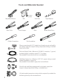
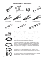
Elbow connection with 3/4” female hose threads on one end and fits
your water supply line (copper tubing, compression fitting, or braided
hose) on the other.
Electrical Supply Cable - Minimum #14 AWG, 2 conductor, 1 ground,
insulated copper conductors rated 75° C or higher.
Only needed if house electrical line is not adequate.
Hot Water Supply Line - Minimum 3/8″ O.D. copper tubing or metal
braided dishwasher supply line.
Only needed if house water supply line is not sucient.
Shut-o valve and fittings appropriate for hot water supply line
(copper tubing/compression fitting, or braided hose).
UL listed conduit connector or strain relief is required if you attach the
field wiring directly to the terminal block.
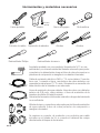
Tools and Materials Needed
Wire Cutter
Needle Nose Pliers
Pliers
Wire Stripper
ø1/16 in
(2 mm)
Adjustable Wrench
Tape Measure
Drill
Hole Saw
Flat Screwdriver
Level
Phillips Screwdriver

7
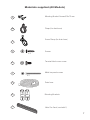
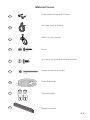
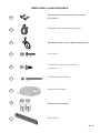
Materials supplied (All Models)
Screw Clamp (for drain hose)
X 5
Mounting Brackets
Mounting Bracket Screws Ø 4x13 mm
D
E
F
B
A
C
G
H
Clamp (for drain hose)
Screws
Terminal block cover screw
Metal toe panel screws
Drain hose
X 2
Metal Toe Panel (used with F)
I

8
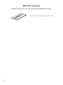
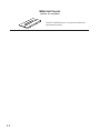
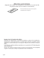
Materials Supplied
(Model Dependent; for fully integrated dishwashers only)
Installation Guide for Fully Integrated Door Panel

9
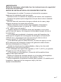
IMPORTANT!
Before you begin, you must read the safety instructions.
PRE-INSTALL CHECKLIST
� Unpack unit. Retain packing material until successful installation is
complete.
� Remove all packing material from inside the dishwasher.
� Inspect parts to ensure you have all the necessary materials.
� Flush household hot water supply for at least two minutes.
� Measure the enclosure area.
� Is the opening at least 34" (863.6 mm) high and 24" (609.6 mm) wide?
� Is the opening near enough to the sink for the water line and drain
hoses to access plumbing?
� Will the unit be installed close enough to the sink so that drain hose
length does not exceed 92" (2336.8 mm) and so that a portion of the
drain hose is raised at least 33" (840 mm) above the oor?
� Do the openings for electric cable, water line, and drain hose routing
through cabinet t within the shaded area in Figure 1?
� Are the openings sanded smooth if wood or covered by a protective
gasket if metal?
� Is your water heater set at 120°F (49°C) and does water pressure
measure 15-145 psi (1-10 bar)?
� If installing in a corner, will the dishwasher door clear cabinet
hardware?
� Determine mounting method based on dishwasher model and
countertop type (see Figures 19-22).
� Only use included hardware for install. If replacing dishwasher,
dispose of old hose and other equipment properly.

10
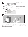
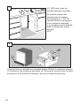
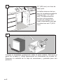
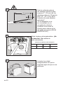
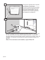
24" (600 mm) with side
strips removed.
Minimum hole size for drain
hose is 1 1/2" (38.1 mm).
Minimum hole size if drain
hose and inlet hose are
through same hole is 2"
(50.8 mm).
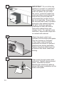
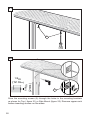
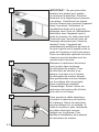
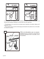
Remove the toe panel (Part I) from the front of the unit and retain for
attachment to the front at a later time. Loosen the leg levelers slightly.
Remove junction box cover and retain for later use (2). Discard the small
piece of protective styrofoam.
4
" (102 mm)
2" (51 mm)
24 - 24
1
/
4
" (610-616 mm)*
90°
24" (610 mm)
33
7
/
8
" (86 cm) min
1
2
I
2

11
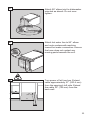
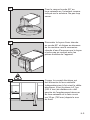
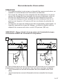
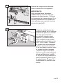
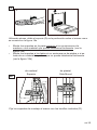
Attach 90° elbow joint to dishwasher
oriented as shown. Do not over-
tighten.
Attach hot water line to 90° elbow
and route underneath machine
toward hot water connection. Ensure
the hose does not contact any
moving parts beneath the unit.
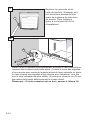
Turn power o at fuse box. Extend
cable approximately 21" (533.4 mm)
from the opening’s left side. Extend
the cable 30" (762 mm) from the
back wall.
3
4
21"
(533.4 mm)
30"
(762 mm)
5

12
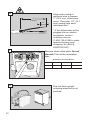
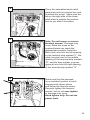
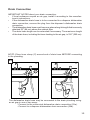
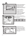
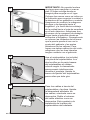
Strip outer casing of
electrical wire to expose
3" (76.2 mm) of the inner
wires. Then strip 1/2" (12.7
mm) casing from each
individual wire.*
* If the dishwasher will be
plugged into an electric
receptacle, contact
customer service
(1-800-735-4328) to order
approved power cord
accessory kit (SKU #
SGZPC001UC).
Flip unit back upright,
ensuring waterline is not
pinched.
Remove strain relief plate. Do not
discard! This will be reinstalled
later.
1/2"
(13mm)
3"
(76mm)
6
8
Do Not Over-tighten or
Remove Terminal Screws
7
Dishwasher Electrical Rating
VoltsHertz AmperesWatts
12060121,450 (max)

13
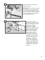
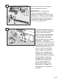
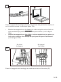
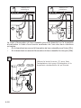
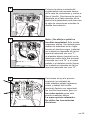
Orient the drain hose toward
direction of sink.
IMPORTANT: Route hose toward
sink PRIOR TO connection. Do
not turn after attachment. Attach
drain hose elbow (Part G) to back
of unit using pliers to install the
spring clamp (Part B).
B
G
B
G
9
Pre-level unit before
positioning under counter
by turning feet clockwise
to raise or counter-
clockwise to lower.
Maximum height the unit
can be raised with feet
fully extended is 34.5"
(876.3 mm). Position
unit under counter to
verify that it is level. If
adjustment is needed,
remove unit from under
counter and adjust as
necessary. Once the
unit is at a satisfactory
height, insert leg leveler
locking screw (Part D)
in back foot. Step 18 will
complete the leveling
process.
D
10

14
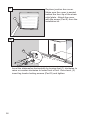
IMPORTANT: Do not allow leg
levelers to scratch or mark oor.
Place hands where pictured to
push into place. As you slide
the unit in, guide the water line
and drain hose toward the sink,
and electric line beneath the
unit toward the junction box at
the front right side. Ensure that
the excess drain hose is pushed
through to the cabinet housing
the sink. Units are typically
positioned so that the door is
ush with cabinet door and
drawer fronts. For optimal noise
reduction, ensure side strips are
in contact with cabinet.
Attach the strain relief (not
included) to the strain relief plate.
The two screws on the back
of the strain relief should be
positioned as shown to prevent
interferences during assembly.
Tighten the strain relief lock nut
to prevent the strain relief from
turning.
Pass wires through strain relief
and plate. Tighten clamp around
wires, oriented as shown.
Bending the electrical cable as
shown will ease installation of the
strain relief plate.
11
12
13

15
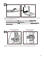
Place the assembled strain relief
plate back into the junction box and
re-attach the screw. Make sure the
tab on the right side of the strain
relief plate is outside the junction
box as you slide it into place.
Do Not Over-tighten or
Remove Terminal Screws
14
Note: Do not loosen or remove
terminal screws! Damage may
occur. Bend the wires so the
exposed leads can reach the
appropriate contacts. Insert the
black (hot) wire into the left opening
on the terminal strip marked “L”, the
white (neutral) wire in the middle
opening of the terminal strip marked
“N”, and the bare copper or green
(ground) wire into the right opening
of the terminal strip marked “G”.
Do Not Over-tighten or
Remove Terminal Screws
15
Make sure that the exposed
(non-insulated) portion of each
stripped wire shows above
and below the terminal screw.
Securely tighten the terminal
screws, but do not over-tighten
or damage may occur.
Hand tighten only. Do not use
power tools.
16

16
Replace junction box cover.
Make sure the cover is seated
behind the front lip of the strain
relief plate. Attach the cover
with the screw (Part E) from the
installation kit.
Warning
............................
..........................................
..........................................
..........................................
..........................................
..........................................
E
17
Level the dishwasher horizontally by turning feet (1) clockwise to
raise or counter-clockwise to lower front of unit. Once level, (2)
insert leg leveler locking screws (Part D) and tighten.
(1)
(2)
D
18

17
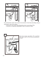
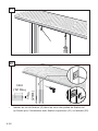
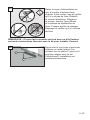
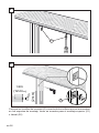
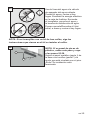
Grasp mounting bracket (H) with pliers and fold bracket at the perforation over
onto itself as shown in 19a.
• Mount brackets on the top if your countertop is wood or other
material that can easily be drilled into. (see gure 19b)
• Mount brackets on the sides if your countertop is stone or any very
hard material that cannot be easily drilled into. (see gure 19b)
19
Attach mounting brackets to the frame with included screws (D).
20
a
Wood Countertop/
Top Mount
Stone Countertop/
Side Mount

18
Drive the mounting screws (A) through the holes in the mounting brackets
as shown for Top ( gure 21) or Side Mount (gure 22). Remove upper rack
before inserting screws on the sides.
21
22
A
A

19
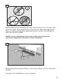
The dishwasher drain hose may be connected to the drain plumbing using
an air gap in one of two ways:
- Connect to the under sink dishwasher drain connection (25a).
- Connect to a disposer dishwasher drain connection (25b).
NOTE: Place hose clamp (C) around end of drain hose BEFORE connecting
to the plumbing.
23
a b
C
C
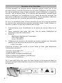
IMPORTANT NOTES about your drain connection:
• If local ordinance require an air gap, install it according to the manufac-
turer’s instructions.
• If the dishwasher drain hose is to be connected to a disposer dishwasher
drain connection, remove the plug from the disposer’s dishwasher drain
connection.
• The dishwasher drain hose must have one place along its length that is securely
attached 33″ (84 cm) above the cabinet oor.
• The drain hose length can be extended if necessary. The maximum length
of the drain hose, including the hose leading to the air gap, is 150″ (380 cm).
Drain Connection

20
min 33” (84 cm)
max 43” (110 cm)
min 33” (84 cm)
max 43” (110 cm)
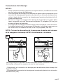
The dishwasher drain hose may be connected to the drain plumbing using a
high loop in one of two ways:
- Connect to the under sink dishwasher drain connection (25c).
- Connect to a disposer dishwasher drain connection (25d).
c
d
C
C
Use the clamp provided (C) to attach
the drain hose to the house plumbing as
shown.
24
C
La page est en cours de chargement...
La page est en cours de chargement...
La page est en cours de chargement...
La page est en cours de chargement...
La page est en cours de chargement...
La page est en cours de chargement...
La page est en cours de chargement...
La page est en cours de chargement...
La page est en cours de chargement...
La page est en cours de chargement...
La page est en cours de chargement...
La page est en cours de chargement...
La page est en cours de chargement...
La page est en cours de chargement...
La page est en cours de chargement...
La page est en cours de chargement...
La page est en cours de chargement...
La page est en cours de chargement...
La page est en cours de chargement...
La page est en cours de chargement...
La page est en cours de chargement...
La page est en cours de chargement...
La page est en cours de chargement...
La page est en cours de chargement...
La page est en cours de chargement...
La page est en cours de chargement...
La page est en cours de chargement...
La page est en cours de chargement...
La page est en cours de chargement...
La page est en cours de chargement...
La page est en cours de chargement...
La page est en cours de chargement...
La page est en cours de chargement...
La page est en cours de chargement...
La page est en cours de chargement...
La page est en cours de chargement...
La page est en cours de chargement...
La page est en cours de chargement...
La page est en cours de chargement...
La page est en cours de chargement...
La page est en cours de chargement...
La page est en cours de chargement...
La page est en cours de chargement...
La page est en cours de chargement...
-
 1
1
-
 2
2
-
 3
3
-
 4
4
-
 5
5
-
 6
6
-
 7
7
-
 8
8
-
 9
9
-
 10
10
-
 11
11
-
 12
12
-
 13
13
-
 14
14
-
 15
15
-
 16
16
-
 17
17
-
 18
18
-
 19
19
-
 20
20
-
 21
21
-
 22
22
-
 23
23
-
 24
24
-
 25
25
-
 26
26
-
 27
27
-
 28
28
-
 29
29
-
 30
30
-
 31
31
-
 32
32
-
 33
33
-
 34
34
-
 35
35
-
 36
36
-
 37
37
-
 38
38
-
 39
39
-
 40
40
-
 41
41
-
 42
42
-
 43
43
-
 44
44
-
 45
45
-
 46
46
-
 47
47
-
 48
48
-
 49
49
-
 50
50
-
 51
51
-
 52
52
-
 53
53
-
 54
54
-
 55
55
-
 56
56
-
 57
57
-
 58
58
-
 59
59
-
 60
60
-
 61
61
-
 62
62
-
 63
63
-
 64
64


dans d''autres langues
- English: Bosch SHE3AR75UC Installation guide
- español: Bosch SHE3AR75UC Guía de instalación
- português: Bosch SHE3AR75UC Guia de instalação
Documents connexes
-
Bosch SHV68R53UC/63 Guide d'installation
-
Bosch SHE43P02UC/59 Manuel utilisateur
-
Bosch SHX98M09UC/49 Manuel utilisateur
-
Gaggenau SHE56C02UC/38 Manuel utilisateur
-
Bosch SHE3AR72UC/22 Guide d'installation
-
Bosch SHX3AR76UC/10 Guide d'installation
-
Bosch SHE4AM16UC/05 Guide d'installation
-
Bosch SGZ1005UC(00) Guide d'installation