Toro 824XL Power Throw Snowthrower Manuel utilisateur
- Catégorie
- Souffleuses à neige
- Taper
- Manuel utilisateur

Operator’s Manual
Manuel de l’Utilisateur
FORM NO. 3321–778
824
XL Power Throw
Snowthrower
Model No. 38084 – 9900001 & Up
824
XL Power Throw
Déneigeuse
Modèle n° 38084 – 9900001 et suivants

EThe Toro Company – 1998
All Rights Reserved
Printed in USA
i
Figures
m-2665
English
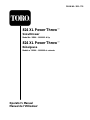
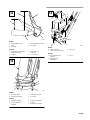
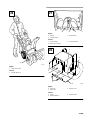
1. Model
and serial number decal
Français
1.
Numéros de modèle et de série
653
English
1. Handle
2.
Capscrews and curved
washers
3.
Axle pin
Français
1. Mancheron
2. Boulons
à tête et rondelles
ondulées
3. Goupille
d’essieu
1 2

ii
m-2669
English
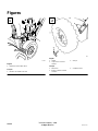
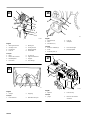
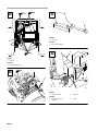
1. T
raction rod
2.
Lower traction rod
Français
1. T
ige de traction
2. T
ige de traction inférieure
m-2665
English
1.
Chute control rod
2. T
raction rod
3. Engine
Français
1. T
ige d’orientation de
l’éjecteur
2. T
ige de traction
3. Moteur
473
English
1.
Axle pin
2.
Outer axle hole
3.
Inner axle hole and wheel
hub
Français
1.
Goupille d’essieu
2. T
rou extérieur de l’essieu
3. T
rou intérieur de l’essieu
et moyeu
m-2672
English
1.
Speed selector arm
2.
Speed selector rod
3.
Flat washer and cotter pin
Français
1.
Bras de changement de
vitesse
2. T
ige de changement de
vitesse
3.
Rondelle plane et goupille
fendue
3
4
5
6

iii
m-2670
1
2
English
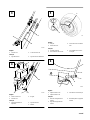
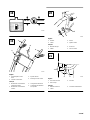
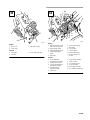
1.
Speed selector rod
2. Trunnion
Français
1. T
ige de changement de
vitesse
2. Tourillon
m-2665
2
1
3
English
1. T
raction control rod
2. Spring
3.
Flange lock nut
Français
1. T
ige de commande de
traction
2. Ressort
3.
Ecrou-frein à collet
1
2
m-2628
3
4
English
1. T
raction control lever
2. Handgrip
3.
Approximately 5 inches
4.
Three to four inches
Français
1.
Manette de commande de
traction
2. Poignée
3.
Environ 12,7 cm
(5 pouces)
4.
7,5 à 10 cm
(3 à 4 pouces)
4
m-2676
1
5
3
2
English
1.
Hex flange nut
2.
Flange lock nut
3.
Upper control rod
4.
Lower control rod
5.
Lower link
Français
1.
Ecrou six pans à collet
2.
Contre-écrou à collet
3. T
ige de commande
supérieure
4. T
ige de commande
inférieure
5. T
ringle inférieure
7
8
9
10

iv
1
2
m-2628
3
4
English
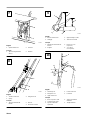
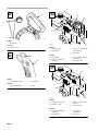
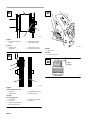
1.
Auger/impeller control
lever
2. Handgrip
3.
Approximately four inches
4. T
wo inches
Français
1.
Manette de commande de
tarière/roue hélice
2. Poignée
3.
Environ 12,7 cm
(4 pouces)
4.
5 cm (2 pouces)
m-168
2
3
1
4
English
1.
Discharge chute
2.
Plastic chute retainer
3.
Chute retainer plate
4.
Chute ring
Français
1.
Goulo
tte d’éjection
2.
Cale de goulotte en
plastique
3.
Plaque de retenue de
goulotte
4.
Anneau de la goulotte
2
m-2665
1
3
English
1.
Chute control rod
2.
Chute control rod bracket
3.
Screw (2)
Français
1. T
ige d’orientation de
l’éjecteur
2.
Support de tige
d’orientation
3. V
is (2)
11
12
13

v
7
1
m-2666
5
8
6
4
3
2
English
1. W
orm gear bracket
2.
Carriage screw
3.
Flat washer
4.
Lock nut
5. W
orm gear
6.
Chute gear rod
7.
Mounting flange
8.
Slotted hole
Français
1. Etrier
2.
Boulon de carrossier
3.
Rondelle plane
4. Ecrou-frein
5. V
is sans fin
6. T
ige d’actionnement
7. Support
8. T
rou allongé
1
171
2
English
1. Scraper 2.
Pipe plug
Français
1.
Lame racleuse
2.
Obturateur de tuyau
5
474
2
1
3
3
4
English
1.
Flange bolt (2)
2. Skid
3.
Flat washer (2)
4.
Lock nut
5. Sideplate
Français
1.
Boulon à collerette (2)
2. Patin
3.
Rondelle plane (2)
4.
Ecrou de blocage
5.
Panneau latéral
2
1
m-2673
English
1. Dipstick 2.
Fuel tank cap
Français
1. Jauge 2.
Bouchon du réservoir
d’essence
14
15
16
17

vi
m-2689
1/4-1/2”
6-13 mm
1
2
3
m-4035
4
English
1.
Auger/impeller control
lever
2. T
raction control lever
3.
Speed selector
4.
Discharge chute control
Français
1.
Manette de commande de
tarière/roue hélice
2.
Manette de commande de
traction
3.
Changement de vitesse
4.
Commande d’orientation
de l’éjecteur
3
1
m-4034
4
2
English
1. Throttle
2. Choke
3. Primer
4.
Ignition switch
Français
1.
Manette des gaz
2. Starter
3. Amorceur
4.
Clé de contact
2
1
3
m-2236
English
1.
Fuel shut–of
f valve
2.
Hose clamp
3.
Fuel line
Français
1.
Robinet d’essence
2. Collier
3.
Conduite d’alimentation
18
19
20
21

vii
934
1
English
1.
Recoil starter
Français
1.
Lanceur à corde
2
1
176
English
1.
Chute deflector handle
2.
Discharge chute
Français
1.
Poignée du déviateur
2. Ejecteur
3
m-2674
2
1
4
English
1.
Spark plug wire
2. Muf
fler guard
3.
Screw (2), lock washer (2)
and washer (2)
4.
Engine bolt
Français
1.
Fil de bougie
2.
Grille de protection du
silencieux
3. V
is (2), rondelles-frein (2)
et rondelles (2)
4.
Boulon du moteur
1
2
m-2675
3
4
English
1.
Carburetor heater box
2.
Phillips screw (2)
3.
Hex head screw and lock
washer
4.
Hex head screw
Français
1.
Boîtier de chauf
fage du
carburateur
2. V
is Phillips (2)
3. V
is six pans et
rondelle-frein
4. V
is six pans
22
23
24
25

viii
m-2680
1
English
1.
Large screw head
Français
1.
Grande tête de vis
1
171
2
3
English
1. Scraper
2.
Carriage screw
3.
Auger blades
Français
1.
Lame racleuse
2.
Boulon de carrossier
3.
Lames de tarière
m-2682
English
1.
Screw (8)
2. Back cover
3.
Bottom cover
Français
1. V
is (8)
2.
Plaque inférieure
3.
Plaque arrière
26 27
28

ix
m-2679
English
1.
Axle gear
Français
1.
Engrenage de l’essieu
m-3331
m-4036
English
1.
Drain plug
Français
1.
Bouchon de vidange
m-26712
1
English
1.
Upper belt cover
2.
Screw (3)
Français
1.
Carter de courroie
supérieur
2. V
is (3)
29
30
31
32

x
m-2678
1
2
3
English
1.
Rear screw
2.
Front screw
3.
Idler pulley spring
Français
1. V
is arrière
2. V
is avant
3.
Ressort de poulie folle
4
1
2
3
5
6
7
m-3331
8
910
11
English
1.
Engine crankshaft screw
,
lock washer and washer
2.
Engine pulley sheave
3.
Auger/impeller drive belt
4.
Large auger/impeller
pulley
5.
Idler pulley
6.
Center engine pulley
7.
Belt guide
8. T
raction belt
9. T
raction pulley
10. T
raction idler pulley
11. Screw
, washer
, lock
washer
Français
1. V
is du vilebrequin,
rondelle-frein et rondelle
2.
Poulie moteur à gorge
3.
Courroie d’entraînement
de tarière/roue hélice
4.
Grande poulie de
tarière/roue hélice
5.
Poulie folle
6.
Poulie moteur centrale
7. Guide-courroie
8.
Courroie de traction
9.
Poulie de traction
10.
Poulie folle de traction
11. Vis,
rondelle,
rondelle-frein
33 34

xi
m-2677
1
2
3
English
1. Indexing
rib in indexing
notch
2.
Engine pulley sheave
3.
Center engine pulley
Français
1.
Relief et creux
d’indexation
2.
Poulie moteur à gorge
3.
Poulie moteur centrale
m-2681
1
2
3
4
English
V
iew from left side of unit
1.
Brake pad
2.
Angled cut-of
f
3.
Auger/impeller drive belt
4. T
raction drive belt
Français
V
ue du côté gauche
1.
Patin de frein
2.
Pan coupé
3.
Courroie d’entraînement
de tarière/roue hélice
4.
Courroie d’entraînement
de traction
m-2678
1
English
1. T
abs in holes
Français
1.
Ergots dans les trous
0.030"
(0.76 mm)
110
35
36
37
38

GB–1
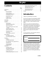
Contents
Page
Introduction 1.
. . . . . . . . . . . . . . . . . . . . . . . . . . .
Safety 2
. . . . . . . . . . . . . . . . . . . . . . . . . . . . . . . . .
Before Operating 2
. . . . . . . . . . . . . . . . . . . .
While Operating 3
. . . . . . . . . . . . . . . . . . . . .
Maintaining Snowthrower 4
. . . . . . . . . . . . .
Sound Pressure Level 4
. . . . . . . . . . . . . . . . .
Sound Power Level 4
. . . . . . . . . . . . . . . . . .
Vibration Level 4
. . . . . . . . . . . . . . . . . . . . .
Symbol Glossary
6
. . . . . . . . . . . . . . . . . . . .
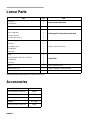
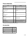
Loose Parts 10
. . . . . . . . . . . . . . . . . . . . . . . . . . . . .
Accessories 10
. . . . . . . . . . . . . . . . . . . . . . . . . . . .
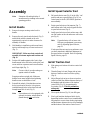
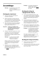
Assembly 11
. . . . . . . . . . . . . . . . . . . . . . . . . . . . . .
Install Handle 11
. . . . . . . . . . . . . . . . . . . . . . .
Install Speed Selector Rod 11
. . . . . . . . . . . . .
Install Traction Rod 11
. . . . . . . . . . . . . . . . . .
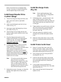
Install Auger/Impeller Drive Control
Linkage 12
. . . . . . . . . . . . . . . . . . . . . . . . . .
Install Dischar
ge Chute
12
. . . . . . . . . . . . . . .
Install Chute Control Gear 12
. . . . . . . . . . . . .
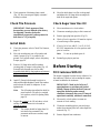
Check Tire Pressure 13
. . . . . . . . . . . . . . . . . .
Install Skids 13
. . . . . . . . . . . . . . . . . . . . . . . .
Check Auger Gear Box Oil 13
. . . . . . . . . . . .
Before Starting 13
. . . . . . . . . . . . . . . . . . . . . . . . . .
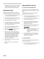
Fill Crankcase With Oil 13
. . . . . . . . . . . . . . .
Fill Fuel Tank W
ith Gasoline
14
. . . . . . . . . . .
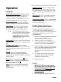
Operation 15
. . . . . . . . . . . . . . . . . . . . . . . . . . . . . .
Controls 15
. . . . . . . . . . . . . . . . . . . . . . . . . . .
Starting/Stopping Engine 15
. . . . . . . . . . . . . .
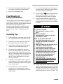
Free Wheeling Or Self–propelled Drive 17
. .
Operating Tips 17
. . . . . . . . . . . . . . . . . . . . . .
Adjusting Scraper 18
. . . . . . . . . . . . . . . . . . . .
Adjusting Skids
18
. . . . . . . . . . . . . . . . . . . . .
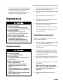
Maintenance 19
. . . . . . . . . . . . . . . . . . . . . . . . . . . .
Draining Gasoline 19
. . . . . . . . . . . . . . . . . . .
Lubricating Snowthrower 19
. . . . . . . . . . . . .
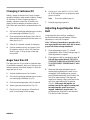
Changing Crankcase Oil
20
. . . . . . . . . . . . . .
Auger Gear Box Oil 20
. . . . . . . . . . . . . . . . . .
Adjusting Auger/Impeller Drive Belt 20
. . . .
Replacing Auger/Impeller Drive Belt 21
. . . .
Replacing Traction Drive Belt 22
. . . . . . . . . .
Adjusting Traction Drive 23
. . . . . . . . . . . . . .
Adjusting Speed Selector 23
. . . . . . . . . . . . . .
Replacing Spark Plug 23
. . . . . . . . . . . . . . . . .
Storage 23
. . . . . . . . . . . . . . . . . . . . . . . . . . . . . . . .
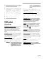
Introduction
Thank you for purchasing a Toro product.
All of us at Toro want you to be completely satisfied
with your new product, so feel free to contact your
local Authorized Service Dealer for help with service,
genuine Toro parts, or other information you may
require.
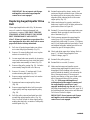
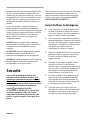
Whenever you contact your Authorized Service
Dealer or the factory, always know the model and
serial numbers of your product. These numbers will
help the Service Dealer or Service Representative
provide exact information about your specific
product. You will find the model and serial number
decal located in a unique place on the product
(Fig. 1).
For your convenience, write the product model and
serial numbers in the space below.
Model No:
Serial No.
Read this manual carefully to learn how to operate
and maintain your product correctly. Reading this
manual will help you and others avoid personal injury
and damage to the product. Although Toro designs,
produces and markets safe, state-of-the-art products,
you are responsible for using the product properly
and safely. You are also responsible for training
persons who you allow to use the product about safe
operation.

GB–2
The Toro warning system in this manual identifies
potential hazards and has special safety messages that
help you and others avoid personal injury, even death.
DANGER, WARNING and CAUTION are signal
words used to identify the level of hazard. However,
regardless of the hazard, be extremely careful.
DANGER signals an extreme hazard that will cause
serious injury or death if the recommended
precautions are not followed.
WARNING signals a hazard that may cause serious
injury or death if the recommended precautions are
not followed.
CAUTION signals a hazard that may cause minor or
moderate injury if the recommended precautions are
not followed.
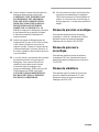
Safety
T
o ensur
e maximum safety, best performance, and
to gain knowledge of the product, it is essential
that you or any other operator of the snowthrower
read and understand the contents of this manual
before the motor is ever started. Pay particular
attention to the safety alert symbol
which
means CAUTION, WARNING OR DANGER —
“personal safety instruction.” Read and
understand the instruction because it has to do
with safety. Failure to comply with instruction
may result in personal injury.
This snowthrower is designed and tested to offer safe
and effective service, provided it is operated in strict
accordance with the following Safety Instructions.
Failure to comply with the following instructions
MA
Y RESUL
T IN PERSONAL INJUR
Y.
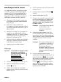
Before
Operating
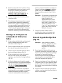
1. Read and understand the contents of this manual
before operating the snowthrower. Become
familiar with all controls and know how to stop
the engine quickly.
2. Keep everyone, especially children and pets,
away from snowthrower and area of operation.
Never allow children to operate the
snowthrower. Adults should operate the
snowthrower only after reading this manual.
3. Thoroughly inspect area thoroughly where
snowthrower will be used. Remove doormats,
sleds, boards, sticks, wire, and any other foreign
objects which might be picked up and thrown by
the snowthrower.
4. Keep all shields and safety devices in place. If a
shield, safety device or decal is illegible,
damaged or lost, repair or replace it before
beginning operation. Also, tighten any loose
nuts, bolts or screws.
5. Wear adequate winter clothing and rubber boots
that will ensure proper footing on slippery
surfaces. Do not wear loose fitting clothing that
could possibly get caught in moving parts.
6. Always wear safety glasses or eye shields during
operation or while performing an adjustment or
repair to protect eyes from foreign objects that
may be thrown from the machine.
7. Adjust both skids so auger housing clears gravel
or crushed rock surfaces.
8. Before starting the engine, ensure auger drive
control and traction (wheel drive) control are in
disengaged position.
9.
Use extension cords and receptacles
10. Always use a grounded, three wire plug and cord
to start snowthrower equipped with an electric
starter. Extension cord must be connected to a
properly grounded outlet.
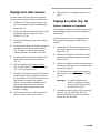
11. Fill fuel tank with gasoline before starting the
engine. A
void spilling any gasoline. Because
gasoline is highly flammable, handle it carefully.
DO NOT SMOKE WHILE HANDLING
GASOLINE.
A. Use an approved gasoline container.

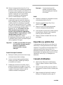
GB–3
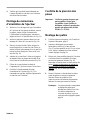
B. Fill fuel tank outdoors, not indoors.
NEVER ADD FUEL T
O AN ENGINE
THAT IS RUNNING OR HOT. Engine
must be cool to reduce potential fire hazard.
C. Open doors if engine will be started in the
garage because exhaust fumes are
dangerous and could possibly be deadly. Do
not run engine indoors.
D. Wipe up any spilled gasoline. Reinstall
gasoline container cap and snowthrower
fuel tank cap securely before starting the
engine.
While
Operating
12. ROTATING
IMPELLER OR AUGER CAN
CUT OFF OR INJURE FINGERS OR
HANDS. STA
Y BEHIND THE HANDLES
AND AWAY FROM DISCHARGE
OPENING WHILE OPERA
TING THE
SNOWTHROWER. KEEP FACE, HANDS,
FEET, AND ANY OTHER PART OF YOUR
BODY OR CLOTHING A
WAY FROM
CONCEALED, MOVING OR ROT
ATING
PARTS.
13.
BEFORE ADJUSTING, CLEANING,
REP
AIRING, AND INSPECTING THE
SNOWTHROWER, AND BEFORE
UNCLOGGING THE DISCHARGE
CHUTE, SHUT ENGINE OFF AND WAIT
FOR ALL MOVING PAR
TS T
O STOP.
ALSO, PULL WIRE OFF SPARK PLUG
AND KEEP WIRE A
WAY FROM THE
PLUG T
O PREVENT ACCIDENT
AL
STARTING. USE A STICK, NOT YOUR
HAND, T
O REMOVE OBSTRUCTIONS
FROM DISCHARGE CHUTE.
14. Before leaving the operator’
s position—behind
the handles—remove key from switch.
15. Allow engine to warm up outdoors before
clearing snow
.
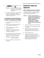
16. Operate the snowthrower only when there is
good visibility or light. Always maintain secure
footing and balance and keep a firm grip on the
handles, especially when operating in reverse.
Walk; never run.
17. Be attentive when using the snowthrower, and
stay alert for holes in the terrain and other
hidden hazards. Be careful when clearing snow
from a gravel drive because stones could be
picked up and thrown if skids are not adjusted so
auger housing clears all rocks.
18. Do not make any adjustments while the engine is
running, with the exception of carburetor
adjustments.
19. Never direct discharge of snow or operate
snowthrower near bystanders, glass enclosures,
automobiles and trucks, window wells or a
drop–off without proper adjustment of the snow
chute and deflector angle.
20. Clear snow from slopes by going up and down,
never across the face. Use caution when
changing directions. Use lower gear when
operating on slopes. Never clear snow from
steep slopes.
21. Do not overload the snowthrower by clearing
snow at too fast a rate.
22. Do not use snowthrower on a roof.
23. If a foreign object is hit or snowthrower vibrates
abnormally, stop engine by turning key to OFF
and wait for all moving parts to stop. Pull wire
off spark plug and check snowthrower
immediately for possible damage, an obstruction
or loose parts. Vibration is generally a sign of
trouble. Repair any damage before starting
engine and operating snowthrower again.

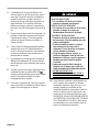
GB–4
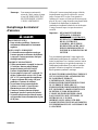
24. Do not touch engine while it is running or soon
after it is stopped because the engine will be hot
enough to cause a burn. Do not add oil or check
oil level in crankcase when engine is running.
25. Never operate snowthrower at high transport
speeds on slippery surfaces. Use care when
backing.
26. Disengage power to the collector/impeller when
snowthrower is transported or not in use.
Maintaining
Snowthrower
27. Perform only those maintenance instructions
described in this manual. Shut engine off before
performing any maintenance service or
adjustment. Additionally, pull wire off spark
plug and keep wire away from plug to prevent
accidental starting. If major repairs are ever
needed, contact your local Authorized TORO
Service Dealer for assistance.
28. Keep snowthrower in safe operating condition
by keeping nuts, bolts, and screws tight. Check
engine mounting bolts frequently to assure they
are tight.
29. Maintain or replace safety and instruction labels,
as necessary
.
30. Do not overspeed the engine by changing
governor settings. Recommended maximum
engine speed is 3450 rpm. To assure safety and
accuracy, check maximum engine speed
(3450 rpm) with a tachometer.
31. Run the machine a few minutes after throwing
snow to prevent freeze-up of the
collector/impeller.
32. Allow engine to cool before storing in an
enclosure such as a garage or storage shed.
NEVER ST
ORE SNOWTHROWER IN
HOUSE (LIVING AREA) OR BASEMENT
BECAUSE GASOLINE AND FUMES ARE
HIGHL
Y FLAMMABLE, EXPLOSIVE,
AND DANGEROUS IF INHALED. Do not
store snowthrower near any open flame or where
gasoline fumes may be ignited by a spark.
33. When storing the snowthrower for an extended
time—off season storage or 30 days—drain
gasoline from fuel tank to prevent a potential
hazard. Store gasoline in a safety–approved fuel
container. Remove key from ignition switch
when storing snowthrower. Store key in a
memorable place.
34. At the time of manufacture, the snowthrower
conformed with or exceeded OPEI safety
standards in effect for snowthrowers. Therefore,
to ensure best performance and safety, purchase
genuine TORO replacement parts and
accessories to keep the TORO all TORO.
NEVER USE “WILL FIT” REPLACEMENT
PAR
TS AND ACCESSORIES.
35.
For safety reasons, use only those accessories
and attachments recommended by The TORO
Company to ensure continued safety certification
of the product. Using unapproved accessories
and attachments could contribute to a potential
hazard.
Sound
Pressure Level
This unit has a sound pressure at the operator’s ear of
93 dB(A), based on measurements of identical
machines per Directive 81/1051/EEC.
Sound
Power Level
This unit has a sound power level of 105 LwA, based
on measurements of identical machines per Directive
79/113/EEC.
Vibration
Level
This unit has a maximum hand-arm vibration level of
15.8 m/s@, based on measurements of identical
machines per EN 1033.

GB–5
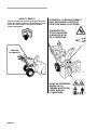
Read and understand the contents of this manual
before operating the snowthrower. Become familiar
with all controls and know how to stop the engine
quickly.
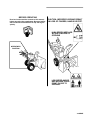
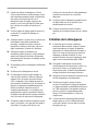
BEFORE OPERATING
OPERATOR'S
POSITION
CAUTION: IMPROPER USE MAY RESULT
IN LOSS OF FINGERS, HANDS OR FEET.
HIGH SPEED IMPELLER
WITHIN 2 INCHES OF
LOW SPEED AUGER
HAS MOVING PINCH
POINT, CLOSE TO
OPENING.
OPENING

GB–6
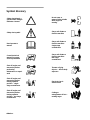
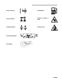
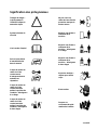
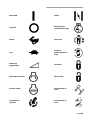
Symbol
Glossary
Safety
alert triangle —
symbol within triangle
indicates a hazard
Do not open or
remove safety shields
while engine is
running
Safety alert symbol
Stay a safe distance
from the machine
Read operator
’s
manual
Stay a safe distance
from the machine –
single stage
snowthrower
Consult technical
manual for proper
service procedures
Stay a safe distance
from the machine –
two stage
snowthrower
Shut off engine and
remove key before
performing
maintenance or repair
work
Thrown or flying
objects — Whole body
exposure
Shut off engine and
remove key before
leaving operator
position – single
stage snowthrower
Electrical shock –
electrocution
Shut off engine and
remove key before
leaving operator
position – two stage
snowthrower
Cutting or
entanglement of foot –
rotating auger

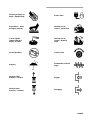
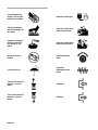
GB–7
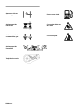
Severing of fingers or
hand – impeller blade
Electric start
Hot surfaces – burns
to fingers or hands
Machine loss of
control – uphill slope
Caustic liquids –
chemical burns to
fingers or hands
Machine loss of
control – downhill
slope
Do not tip battery T
raction drive
Keep dry
Snowthrower collector
auger
Machine travel
direction – forward
Engage
Machine travel
direction – rearward
Disengage

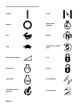
GB–8
On/start Choke
Off/stop
Engine speed
(Throttle)
Fast Neutral
Slow
Snowthrower collector
auger
Decreasing/Increasing Lock
Engine start
Unlock
Engine stop
Lever operation
Snowthrower chute
direction
Lever operation
La page est en cours de chargement...
La page est en cours de chargement...
La page est en cours de chargement...
La page est en cours de chargement...
La page est en cours de chargement...
La page est en cours de chargement...
La page est en cours de chargement...
La page est en cours de chargement...
La page est en cours de chargement...
La page est en cours de chargement...
La page est en cours de chargement...
La page est en cours de chargement...
La page est en cours de chargement...
La page est en cours de chargement...
La page est en cours de chargement...
La page est en cours de chargement...
La page est en cours de chargement...
La page est en cours de chargement...
La page est en cours de chargement...
La page est en cours de chargement...
La page est en cours de chargement...
La page est en cours de chargement...
La page est en cours de chargement...
La page est en cours de chargement...
La page est en cours de chargement...
La page est en cours de chargement...
La page est en cours de chargement...
La page est en cours de chargement...
La page est en cours de chargement...
La page est en cours de chargement...
La page est en cours de chargement...
La page est en cours de chargement...
La page est en cours de chargement...
La page est en cours de chargement...
La page est en cours de chargement...
La page est en cours de chargement...
La page est en cours de chargement...
La page est en cours de chargement...
La page est en cours de chargement...
La page est en cours de chargement...
La page est en cours de chargement...
La page est en cours de chargement...
La page est en cours de chargement...
La page est en cours de chargement...
-
 1
1
-
 2
2
-
 3
3
-
 4
4
-
 5
5
-
 6
6
-
 7
7
-
 8
8
-
 9
9
-
 10
10
-
 11
11
-
 12
12
-
 13
13
-
 14
14
-
 15
15
-
 16
16
-
 17
17
-
 18
18
-
 19
19
-
 20
20
-
 21
21
-
 22
22
-
 23
23
-
 24
24
-
 25
25
-
 26
26
-
 27
27
-
 28
28
-
 29
29
-
 30
30
-
 31
31
-
 32
32
-
 33
33
-
 34
34
-
 35
35
-
 36
36
-
 37
37
-
 38
38
-
 39
39
-
 40
40
-
 41
41
-
 42
42
-
 43
43
-
 44
44
-
 45
45
-
 46
46
-
 47
47
-
 48
48
-
 49
49
-
 50
50
-
 51
51
-
 52
52
-
 53
53
-
 54
54
-
 55
55
-
 56
56
-
 57
57
-
 58
58
-
 59
59
-
 60
60
-
 61
61
-
 62
62
-
 63
63
-
 64
64


Toro 824XL Power Throw Snowthrower Manuel utilisateur
- Catégorie
- Souffleuses à neige
- Taper
- Manuel utilisateur
dans d''autres langues
Documents connexes
-
Toro 724 Snowthrower Manuel utilisateur
-
Toro 622 Snowthrower Manuel utilisateur
-
-
-
-
Toro 1232 Power Shift Snowthrower Manuel utilisateur
-
-
Toro Power Max 724 OE Snowthrower Manuel utilisateur
-
Toro 1028 Power Shift Snowthrower Manuel utilisateur
-