Bosch HBN3450UC/09 Guide d'installation
- Catégorie
- Micro-ondes
- Taper
- Guide d'installation

installation Manual
Guide d'installation
Manual de instalaci6n
Built-in Ovens
Models: HBL33, HBL34, HBN34, HBL35, HBN35, HBL54, HBN54,
HBL56, HBN56, HBL57, HBL8450, HBL8650, HBL8750
@
,,lllllllllllllllh_
_,,_ ,, ,
,,,,,,,,,,,,,,,,,,
....._,_f;'
\
' ,,,u
_' illlllllllllllllllll,i.... _
,,,,,,,,,,,,,,,,,,.....
,,,,,,,,,,,,,,,,,,,,,,,,,,,,,,

Table of Contents
Safety ....................................................... 1
Important Safety Instructions ..................................... 1
Preparation .................................................. 2
Before you Begin ............................................... 2
Tools and Parts Needed ...................................................... 2
Parts Included .............................................................. 2
General Information .......................................................... 2
Dimensions for 27" Wall-Mounted Units ............................. 3
Dimensions for 27" under the counter ............................................ 4
Dimensions for 30" Wall-Mounted Units ............................. 5
Dimensions for 30" under the counter ............................................ 7
Removing Packaging ............................................ 7
For Convection Microwave Combination Units ..................................... 7
Preparing Oven ............................................................. 8
Microwave Combination Units Adjustment Feature .................................. 9
Installation ................................................. 10
Electrical Installation ........................................... 10
Oven Installation ............................................... 11
Testing Operation .............................................. 11
Service ..................................................... 12
Before Calling Service ....................................................... 12
This Bosch Appliance is made by BSH
Home Appliances Corporation
1901 Main Street, Suite 600
Irvine, CA 92614
Questions?
1-800-944-2904
www.boschappliances.com
We look forward to hearing from you!

Safety
Important Safety
Instructions
READ AND SAVE THESE
INSTRUCTIONS
WARNING:
If the information in this manual is not followed exactly, fire
or shock may result causing property damage or personal
injury.
WARNING:
Do not repair or replace any part of the appliance unless
specifically recommended in the manuals. Improper
installation, service or maintenance can cause injury or
property damage. Refer to this manual for guidance. All
other servicing should be done by a qualified technician.
Appliance Handling Safety
Do not lift appliance by door handle. Remove the door for
easier handling and installation. See instructions in Use
and Care Manual.
Unit is heavy and requires at least two people or proper
equipment to move.
Hidden surfaces may have sharp edges. Use caution when
reaching behind or under appliance.
Safety Codes and Standards
This appliance complies with one or more of the following
Standards:
• UL 858, The Standard for the Safety of Household
Electric Ranges
• UL 923, The Standard for the Safety of Microwave
Cooking Appliances
• UL 507, The Standard for the Safety of Electric Fans
ANSI Z21.1, The American National Standard for
Household Cooking Gas Appliances
CAN/CSA-C22.2 No. 113-M1984 Fans and Ventilators
CAN/CSA-C22.2 No. 61-M89 Household Cooking
Ranges
It is the responsibility of the owner and the installer to
determine if additional requirements and/or standards
apply to specific installations.
Electric Safety
Before you plug in an electrical cord, be sure all controls
are in the OFF position.
If required by the National Electrical Code (or Canadian
Electrical Code), this appliance must be installed on a
separate branch circuit.
Installer - show the owner the location of the circuit
breaker or fuse. Mark it for easy reference.
Important - Save these instructions for the local electrical
inspector's use.
Before installing, turn power OFF at the service panel. Lock
service panel to prevent power from being turned ON
accidentally.
Refer to data plate for more information. See "Data Plate"
under "Service" for data plate location.
Be sure your appliance is properly installed and grounded
by a qualified technician. Installation, electrical connections
and grounding must comply with all applicable codes.
Related Equipment Safety
Remove all tape and packaging before using the appliance.
Destroy the packaging after unpacking the appliance.
Never allow children to play with packaging material.
Never modify or alter the construction of the appliance. For
example, do not remove leveling legs, panels, wire covers
or anti-tip brackets/screws.
English 1

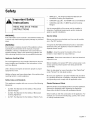
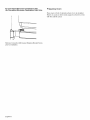
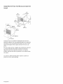
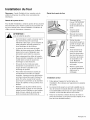
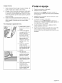
Transport
To avoid damage to the oven vent, use the transport
method shown in the picture below.
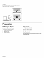
Preparation
Before you Begin
Tools and Parts Needed
• Phillips head screwdriver
• Measuring tape
• Drill with bit (1/8")
Parts Included
• Phillips head screws (6)
General Information
Power Requirements
The outlet must be properly grounded in accordance with
all applicable codes.
English 2

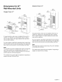
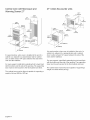
Dimensions for 27"
Wall-Mounted Units
Single Oven 27"
24"
(610ram)
251/2"
24t3/16"
23W8" (606mm)
(718mm)
J 22" (559mm)
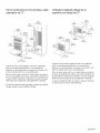
It is good practice, when oven is installed at the end of a
cabinet run, adjacent to a perpendicular wall or cabinet
door, to allow at least 114" space between the side of the
oven and the wall/door.
For oven support, install 2x4's extending front to back flush
with the bottom and the side of the opening. The supporting
base must be well secured to the floor/cabinet and level.
Note:
The conduit box must be installed either above or below the
unit. If the conduit box is installed below the unit, a 2"
diameter hole or space is required between the back wall
and the right rear of the 2x4 supports.
The cabinet base must be flat and capable of supporting a
weight of at least 193 Ibs (87 kg).
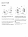
Double Oven 27"
251/2"
513f4"
(131 imm)
It is good practice, when oven is installed at the end of a
cabinet run, adjacent to a perpendicular wall or cabinet
door, to allow at least 114"space between the side of the
oven and the wall/door.
For oven support, install 2x4's extending front to back flush
with the bottom and the side of the opening. The supporting
base must be well secured to the floor/cabinet and level.
Note:
The conduit box must be located above the unit to facilitate
connecting and servicing.
The cabinet base must be flat and capable of supporting a
weight of at least 361 Ibs (164 kg).
English 3

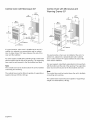
Combo Oven with Microwave and
Warming Drawer 27"
6 1 318"
(1559mm)
595/8"
(1514turn)
mino 43N"
max, 12318"(315mm)
It is good practice, when oven is installed at the end of a
cabinet run, adjacent to a perpendicular wall or cabinet
door, to allow at least 114" space between the side of the
oven and the wall/door.
For oven support, install 2x4's extending front to back flush
with the bottom and the side of the opening. The supporting
base must be well secured to the floor/cabinet and level.
The cabinet base must be flat and capable of supporting a
weight of at least 369 Ibs (167 kg).
27" Under-the-counter units
24"
(610ram)
43/4"
(121mm)
It is good practice, when oven is installed at the end of a
cabinet run, adjacent to a perpendicular wall or cabinet
door, to allow at least 114"space between the side of the
oven and the wall/door.
For oven support, install 2x4's extending front to back flush
with the bottom and the side of the opening. The supporting
base must be well secured to the floor/cabinet and level.
The cabinet base must be flat and capable of supporting a
weight of at least 193 Ibs (87 kg).
English 4

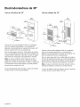
Dimensions for 30"
Wall-Mounted Units
Single Oven 30"
281/2"
It is good practice, when oven is installed at the end of a
cabinet run, adjacent to a perpendicular wall or cabinet
door, to allow at least 114" space between the side of the
oven and the wall/door.
For oven support, install 2x4's extending front to back flush
with the bottom and the side of the opening. The supporting
base must be well secured to the floor/cabinet and level.
Note:
The conduit box must be installed either above or below the
unit. If the conduit box is installed below the unit, a 2"
diameter hole or space is required between the back wall
and the right rear of the 2x4 supports.
The cabinet base must be flat and capable of supporting a
weight of at least 212 Ibs (96 kg).
Double Oven 30"
2713/16"
(706ram)
28112"
It is good practice, when oven is installed at the end of a
cabinet run, adjacent to a perpendicular wall or cabinet
door, to allow at least 114"space between the side of the
oven and the wall/door.
For oven support, install 2x4's extending front to back flush
with the bottom and the side of the opening. The supporting
base must be well secured to the floor/cabinet and level.
Note:
The conduit box must be located above the unit to facilitate
connecting and servicing.
The cabinet base must be flat and capable of supporting a
weight of at least 390 Ibs (177 kg).
English 5

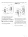
Combo Oven with Microwave 30"
(1270mm)
It is good practice, when oven is installed at the end of a
cabinet run, adjacent to a perpendicular wall or cabinet
door, to allow at least 114" space between the side of the
oven and the wall/door.
For oven support, install 2x4's extending front to back flush
with the bottom and the side of the opening. The supporting
base must be well secured to the floor/cabinet and level.
Note:
The conduit box must be located above the unit to facilitate
connecting and servicing.
The cabinet base must be flat and capable of supporting a
weight of at least 310 Ibs (141 kg).
Combo Oven with Microwave and
Warming Drawer 30"
It is good practice, when oven is installed at the end of a
cabinet run, adjacent to a perpendicular wall or cabinet
door, to allow at least 114"space between the side of the
oven and the wall/door.
For oven support, install 2x4's extending front to back flush
with the bottom and the side of the opening. The supporting
base must be well secured to the floor/cabinet and level.
Note:
The conduit box must be located above the unit to facilitate
connecting and servicing.
The cabinet base must be flat and capable of supporting a
weight of at least 429 Ibs (195 kg).
English 6

Dimensions for 30" Under-the-counter
Units
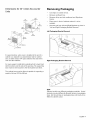
Removing Packaging
• Cut straps on outside of box.
• Remove cardboard box.
• Remove all top and side cardboard and Styrofoam
braces.
• Place oven in front of cabinets where it is to be
installed.
• Unscrew unit from Left and Right Brackets as show in
"Left and Right Packaging Bracket Removal."
Left Packaging Bracket Removal
It is good practice, when oven is installed at the end of a
cabinet run, adjacent to a perpendicular wall or cabinet
door, to allow at least 114" space between the side of the
oven and the wall/door.
For oven support, install 2x4's extending front to back flush
with the bottom and the side of the opening. The supporting
base must be well secured to the floor/cabinet and level.
The cabinet base must be flat and capable of supporting a
weight of at least 212 Ibs (96 kg).
Right Packaging Bracket Removal
Note:
Different models use different packaging materials. Actual
brackets may look differently. Bracket remains in packaging
base. Unit should stay on packaging base until ready to be
lifted into cabinet cutout.
English 7

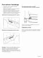
For Convection Microwave Combination Units
(for Convection Microwave Combination Units Only)
Preparing Oven
Place oven in front of cabinets where it is to be installed.
Rest it on a jack or other sturdy support so that it is in line
with the cabinet cutout.
Remove Convection Microwave Shipping Bracket Screw
prior to installation.
English 8

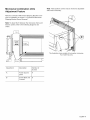
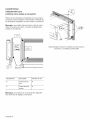
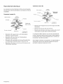
Microwave Combination Units
Adjustment Feature
Remove Convection Microwave Shipping Bracket screw
prior to installation as shown in "Convection Microwave
Shipping Bracket Screw Removal."
Note: To adjust the fit between the microwave frame and
kitchen cabinet, refer to the following diagrams and
charts.
Note: Fixed position screws may be moved to adjustable
slots when necessary.
This illustration shows models with convection microwave.
Your model may vary.
Adjustment Description Number of
Screws
A Frame Up and 4
Down
B Frame Back and 8
Forward
English 9

..................................................................................................................................................................................................................................................................................................._iii_iii_!ii_!ii_!ii_!ii_!ii_!ii_!ii_!ii_!ii_!ii_!ii_!ii_!ii_!ii_!ii_!ii_!ii_!ii_!ii_!ii_!ii_!ii_!ii_!ii_!ii_!ii_!ii_ _iiiiii!_ii!_ii!_ii!_ii!_ii!_ii!_ii!_ii!_ii!_ii!_ii!_ii!_ii!_ii!_ii!_ii!_ii!_ii!_ii!_ii!_ii!_ii!_ii!_ii!_ii!_ii!_ii!_iiiiii__i_
Installation
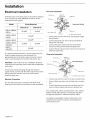
Electrical Installation
All model ovens on the front cover are dual rated, designed
to be connected to either 208/240V AC, 60 Hz, 4 wire,
single-phase power supply.
Model Circuit Required
208V, 60 Hz 240V, 60 Hz
HBL33, HBN34, 25 AMP 30 AMP
HBL34
HBN54, HBL54
30 AMP
HBL84
HBN35, HBL35 40 AMP
HBN56, HBL56, 30 AMP 40 AMP
HBL8650,
HBL57, 50 AMP
HBL8750
The electrical supply should be a 4-wire single-phase AC.
Install a suitable conduit box (not furnished). An
appropriately-sized, UL-listed conduit connector must be
used to correctly attach the conduit to the junction box.
Important: Local Codes may vary; installation, electrical
connections and grounding must comply with all applicable
local codes.
If local codes permit grounding through the electrical
supply neutral, connect both the white neutral wire and the
bare ground wire from the oven to the white neutral
electrical supply wire.
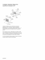
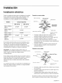
Electrical Connection
The four-wire connection is preferred, but where local
codes permit, the three wire connection is also acceptable.
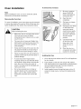
Four-wire Connection
Junction box.\ Cable from
\\ power supply
Red wires
White wires
Ungrounded Neutral
"""-..\ Black wires
Bare or green wires Cable
from oven "\ U.L.-listed conduit connector
• Connect the red oven wire to the red electrical supply
wire (hot wire).
• Connect the black oven wire to the black electrical
supply wire (hot wire).
• Connect the white neutral oven wire to the white
neutral (not bare ground) electrical supply wire.
• Connect the bare ground oven wire to the bare ground
electrical supply wire.
Three-wire Connection
Juncti°n b°x _eer f_°pmply
Whitewires Redwires_ _ _ Grounded Neutral
from oven
• Connect red wire from oven to red wire in junction box.
• Connect black wire from oven to black wire in junction
box.
• Connect both green ground wire and white wire from
oven to white (or gray) neutral wire in junction box.
The conduit cable, where connected at the oven, swivels.
Rotate conduit cable upward (or downward) and direct
through hole prepared in cabinet to attach to J-Box.
To maintain serviceability, the flex conduit must not be
shortened and should be routed to permit temporary
removal of the oven.
English 10

Oven Installation
Note:
Before installing the oven, be sure to verify the cabinet
dimensions and electrical connections.
Removing the Oven Door
For ease of installation, some oven doors may be removed
to reduce the weight of the oven by 30 Ibs (14 kg) per door,
before installing into the cabinet. See instructions below.
,_ CAUTION:
When removing the door:
Make sure oven is cool and power to the
oven has been turned off before
removing the door. Failure to do so could
result in burns.
• The oven door is heavy and fragile. Use
both hands to remove the oven door. The
door front is glass. Handle carefully to
avoid breaking.
• Grasp only the sides of the oven door. Do
not grasp the handle as it may swing in
your hand and cause damage or injury.
• Failure to grasp the oven door firmly and
properly could result in personal injury or
product damage.
• To avoid injury from hinge bracket
snapping closed, be sure that both levers
are securely in place before removing the
door. Also, do not force door open or
closed - the hinge could be damaged and
injury could result.
• Do not lay removed door on sharp or
pointed objects as this could break the
glass. Lay on a flat, smooth surface,
positioned so that the door cannot fall
over.
To remove the oven door:
, Be sure to read the
above CAUTION
before attempting to
remove the door.
2. Open the door
completely.
3. Flip levers on hinges
toward you.
4. Holding the door firmly
on both sides and
using both hands,
close the door gently
until it stops against
the levers, about 30°
from the closed
position.
5. Carefully lift the door
up and out of the
hinge slots. Hold
firmly; the door is
heavy.
6. Place the door in a
convenient and stable
location for cleaning.
Installing the Oven
1. Liftor slide unit into cabinet cutout. Do not lift appliance
by door handle.
2. Push straight in until oven trim is flush with cabinet
wall, being careful not to crimp flexible conduit between
oven and cabinet back wall. The oven should be
straight and level, not crooked.
3. Install supplied screws through tap holes in trim. (2
screws for single ovens, 4 screws for double/combo
ovens)
English 11

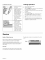
To replace the oven door:
J
,
2.
,
Hold the door firmly in
both hands.
Hold the door at a 30°
angle from the closed
position and insert
hinges into the slots.
You may need to rock
the door forward and
backward slightly to
seat the hinge feet.
The door may need to
be removed and re-
inserted until the
hinges sit correctly in
the slots.
4. Open door all the way
to expose hinges,
levers, and slots.
5. Push levers forward
and down until seated
on the bracket.
,
Close and open door
slowly to be sure it is
correctly and securely
in place. Door must be
straight, not crooked.
Testing Operation
1. Turn on power at the breaker.
2. Test the oven mode.
Select the BAKE mode. See the Use and Care Manual
for detailed operation instructions.
3. Verify that the oven light comes on and the oven begins
to preheat.
4. Test the door lock.
Set the SELF CLEAN mode. Confirm that the door
locks when the lock icon appears in the display.
5. If installing a double oven, test the second oven as
well.
6. If any of the tests do not result as explained above,
contact Bosch service for assistance. Otherwise, the
installation is complete at this time.
Service
Before Calling Service
See Use and Care Manual for troubleshooting information.
Refer to the Warranty in the Use and Care Manual.
To reach a service representative, see the contact
information at the front of the manual. Please be prepared
with the information printed on your product data plate
when calling.
Data Plate
The data plate shows the model and serial number. Refer
to the data plate on the appliance when requesting service.
The data plate is located on the underside of the control
panel:
English 12

English13

Table des mati res
Sdcuritd ..................................... 1
Consignes de securit6 importantes ................................... 1
Prdparation .................................. 3
Avant de commencer ............................................. 3
Outils et pieces necessaires ................................................... 3
Pieces incluses ............................................................. 3
Appareils electrom6nagers de 27 po ................................. 3
Informations generales ....................................................... 3
Appareils electrom6nagers de 30 po ................................. 6
Pourenlever I'emballage ........................................... 9
Caracteristique d'adjustement pour combine micro-ondes a convection ........... 9
Installation ................................. 11
Installation electrique ............................................ 12
Raccordement electrique ..................................................... 12
Installation du four ............................................... 13
Test de contr61e ................................................ 14
Ddpannage ................................. 15
Avant d'appeler le service de depannage ........................................ 15
Cet appareil 61ectromenager de Bosch est fait par
BSH Home Appliances Ltd.
6696 Financial Drive, Unit 3
Mississauga, ON L5N 7J6
Questions ?
1-800-944-2904
www. bosch-home.ca
Nous attendons de vos nouvelles !

S6curitd
Consignes de
sdcuritd
importantes
LIRE ET CONSERVER CES
CONSIGNES
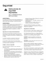
AVERTISSEMENT:
si les informations de ce manuel ne sont pas suivies _ la
lettre, un incendie ou un choc 61ectrique peuvent se
produire et sont susceptibles de causer des dommages
mat@iels ou des 16sions corporelles.
AVERTISSEMENT:
ne pas r6parer ni remplacer des pi_ces de I'appareil
moins que cela ne soit express6ment recommand6 dans le
manuel. Toute installation, r6paration ou maintenance
inad6quate peut entrafner des blessures ou des
dommages mat@iels. Consulter ce manuel pour obtenir
des conseils sur la fagon de proc6der. Tousles travaux
d'entretien doivent 6tre confi6s _ un technicien qualifi6.
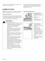
Securite de manipulation de rappareil
Ne pas soulever I'appareil par la poign6e de la porte.
Enlever la porte pour faciliter la manipulation et I'installation
de I'appareil. Voir les instructions du Manuel d'utilisation et
d'entretien.
Cet appareil est Iourd et il faut au moins deux personnes ou
1'6quipement appropri6 pour le d6placer.
Les surfaces cach6es peuvent comporter des ar_tes vives.
Faites attention en 6tendant le bras derri@e I'appareil ou
en dessous.
Codes et normes de securite
Cet appareil est conforme _ une ou plusieurs des normes
suivantes :
• UL 858, Norme pour la s6curit6 des cuisini_res
61ectriques domestiques
• UL 923, Norme pour la s6curit6 des appareils de
cuisson _ micro-ondes
• UL 507, Norme pour la s6curit6 des ventilateurs
61ectriques
• ANSI Z21.1, Norme nationale am6ricaine pour les
appareils de cuisson _ gaz domestiques
CAN/CSA-C22.2 No. 113-M 1984, Ventilateurs et
soufflantes
CAN/CSA-C22.2 No. 61-M89, Cuisini@es pour usage
m6nager
II incombe au propri6taire et _ I'installateur de d6terminer si
des exigences et/ou normes additionnelles s'appliquent
pour des installations sp6cifiques.
Securite electrique
Avant de brancher le cordon 61ectrique, v@ifier que toutes
les commandes sont dans la position "OFF" (Arr6t).
S'il y a lieu, conform6ment au Code national de 1'61ectricit6
(ou au Code canadien de 1'61ectricit6),cet appareil doit 6tre
install6 sur un circuit de d@ivation s6par6.
Installateur - indiquer au propri6taire I'emplacement du
disjoncteur ou du fusible. Identifier sa position pour pouvoir
le retrouver facilement plus tard.
Important - Conserver ces instructions pour I'usage de
I'inspecteur local en 61ectricit6.
Avant I'installation, couper le courant au panneau de
service. Verrouiller le panneau de service pour 6viter que le
courant ne soit accidentellement r6tabli.
Pour plus d'informations, se reporter _ la plaque
signal6tique. Pour connaftre I'emplacement de la plaque
signal6tique, voir "Plaque signal6tique" sous "Entretien".
S'assurer que I'appareil est ad6quatement install6 et mis
la terre par un technicien qualifi6. L'installation, les
connexions 61ectriques et la mise _ la terre doivent 6tre
conformes _ tousles codes applicables.
Securite apparentee concernant I'equipement
Retirer le ruban adh6sif et I'emballage avant d'utiliser
I'appareil. D6truire I'emballage apr_s avoir d6ball6
Frangais 1

I'appareil.Nejamaislaisserlesenfantsjoueravecles
mat@iauxdeconditionnement.
Nejamaismodifiernialt@erlaconfigurationdeI'appareil.
Parexemple,nepasretirerlespiedsdenivellement,les
panneaux,lescouverclesdec_blageoulesfixations/vis
antibasculement.
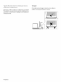
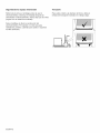
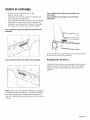
Transport
Pour 6viter tout dommage _ 1'6vent du four, utiliser la
m6thode de transport illustr6e ci-dessous.
Frangais 2

Prdparation
Avant de commencer
Outils et pieces necessaires
• Toumevis _ t_te Phillips
• Ruban _ mesurer
• Perceuse avec foret (1/8 po)
Pieces incluses
• Vis cruciformes (6)
Informations gen6rales
Exigences electriques
• La prise doit _tre correctement reli6e _ la terre selon
tous les codes applicables.
Fran9ais 3

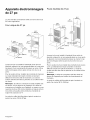
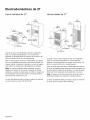
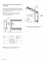
Appareils dlectromdnagers
de 27 po
La prise doit _tre correctement reli6e _ la terre selon tous
les codes applicables.
Four unique de 27 po
Fours doubles de 27 po
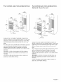
Lorsque le four est install6 _ I'extr6mit6 d'une s6rie de
placards, adjacent _ un mur perpendiculaire ou _ une porte
de placard, il est recommand6 de laisser au moins 1/4 po
(0,6 cm) d'espace entre la paroi du four et lemur ou la
porte.
Pour le soutien du four, installer des montants de 2 pouces
sur 4 qui s'6tendent de I'avant _ I'arri_re et viennent
affleurer le fond et le c6t6 de I'ouverture. Le socle de
soutien doit 6tre bien fix6 au plancher ou au coffret et 6tre
de niveau.
Remarque : la boTte de connexions doit _tre install6e soit
au-dessus, soit au-dessous de I'appareil. Si la boTte de
connexions est install6e sous I'appareil, un espace ou une
ouverture de 2 po (5,8 cm) de diam_tre est requis entre le
mur arri_re et la partie arri_re droite des montants de
support de 2 pouces sur 4.
Le socle du coffret doit _tre plate et apte _ soutenir un
poids d'au moins 193 Ib (87 kg).
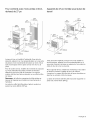
51314"
(!31imm)
Lorsque le four est install6 _ I'extr6mit6 d'une s6rie de
placards, adjacent _ un mur perpendiculaire ou _ une porte
de placard, il est recommand6 de laisser au moins 1/4 po
(0,6 cm) d'espace entre la paroi du four et lemur ou la
porte.
Pour le soutien du four, installer des montants de 2 pouces
sur 4 qui s'6tendent de I'avant _ I'arri_re et viennent
affleurer le fond et le c6t6 de I'ouverture. Le socle de
soutien doit 6tre bien fix6 au plancher ou au coffret et 6tre
de niveau.
Remarque : la bofte de connexions doit 6tre situ6e au-
dessus de I'appareil pour faciliter les branchements et
I'entretien.
Le socle du coffret doit _tre plate et apte _ soutenir un
poids d'au moins 361 Ib (164 kg).
Frangais 4
La page est en cours de chargement...
La page est en cours de chargement...
La page est en cours de chargement...
La page est en cours de chargement...
La page est en cours de chargement...
La page est en cours de chargement...
La page est en cours de chargement...
La page est en cours de chargement...
La page est en cours de chargement...
La page est en cours de chargement...
La page est en cours de chargement...
La page est en cours de chargement...
La page est en cours de chargement...
La page est en cours de chargement...
La page est en cours de chargement...
La page est en cours de chargement...
La page est en cours de chargement...
La page est en cours de chargement...
La page est en cours de chargement...
La page est en cours de chargement...
La page est en cours de chargement...
La page est en cours de chargement...
La page est en cours de chargement...
La page est en cours de chargement...
La page est en cours de chargement...
La page est en cours de chargement...
La page est en cours de chargement...
La page est en cours de chargement...
-
 1
1
-
 2
2
-
 3
3
-
 4
4
-
 5
5
-
 6
6
-
 7
7
-
 8
8
-
 9
9
-
 10
10
-
 11
11
-
 12
12
-
 13
13
-
 14
14
-
 15
15
-
 16
16
-
 17
17
-
 18
18
-
 19
19
-
 20
20
-
 21
21
-
 22
22
-
 23
23
-
 24
24
-
 25
25
-
 26
26
-
 27
27
-
 28
28
-
 29
29
-
 30
30
-
 31
31
-
 32
32
-
 33
33
-
 34
34
-
 35
35
-
 36
36
-
 37
37
-
 38
38
-
 39
39
-
 40
40
-
 41
41
-
 42
42
-
 43
43
-
 44
44
-
 45
45
-
 46
46
-
 47
47
-
 48
48


Bosch HBN3450UC/09 Guide d'installation
- Catégorie
- Micro-ondes
- Taper
- Guide d'installation
dans d''autres langues
- English: Bosch HBN3450UC/09 Installation guide
- español: Bosch HBN3450UC/09 Guía de instalación
Documents connexes
-
Bosch HBN5450UC/07 Guide d'installation
-
Bosch HBL35 Guide d'installation
-
Bosch HMC80251UC/01 Guide d'installation
-
Bosch HBN5620UC/01 Guide d'installation
-
-
Bosch HWD3060UC/02 Guide d'installation
-
-
-
Bosch HBN5450UC/06 Le manuel du propriétaire
-
Autres documents
-
 BoschHome HBN34 Guide d'installation
-
Siemens HF35M630/01 Guide d'installation
-
Thermador MEDMC301JS Guide d'installation
-
Gaggenau BM281710/01 Guide d'installation
-
KitchenAid KSSC36FMS01 Guide d'installation
-
Maytag MDBTT53AWB0 Guide d'installation
-
Amana ADB1600AWB2 Guide d'installation
-
Thermador PRD304EG/07 Guide d'installation
-
Kenmore 79040619800 Guide d'installation
-
Thermador ME271 Guide d'installation
