Asco Series 551 552 553 Solenoid Valves Le manuel du propriétaire
- Taper
- Le manuel du propriétaire

INSTALLATIONGB
MISE EN SERVICEFR
FONCTION
Electrodistributeurs 3/2 NF ou 5/2, taraudés 1/4-3/8-1/2 ou à plan de pose NAMUR
Les versions avec pilotes filetés 15/16"-26 UNS sont utilisables avec alimentation interne ou externe de la pression de pilotage.
Sauf demande spécifique (TPL20547), ce type d'électrodistributeur est livré d'origine avec alimentation interne.
RACCORDEMENT ALIMENTATION DE PILOTAGE (1/8)
1. Dévisser et enlever le bouchon protecteur (4) avec une clé 6 pans de 5 mm (fig.A1-A2)
2. Raccorder l'alimentation externe de pilotage (Pp) (fig.A1-A3). Pression d'alimentation du pilotage : 2 à 10 bar
NOTA : En cas de retour à l'alimentation interne de pilotage, procéder comme ci-dessus en veillant à placer correctement les joints de
sélection en position alimentation interne, déconnecter le (les) raccord(s) d'alimentation, replacer le (les) bouchon(s) 1/8 (4), étancher à
la loctite 542, couple maxi : 6 N.m
ADAPTATION EN ALIMENTATION EXTERNE
■ ELECTRODISTRIBUTEUR MONOSTABLE
1. Desserrer et enlever les 2 vis (1) de l'embout commande avec
une clé 6 pans de 3 mm (551) ou de 4 mm (552-553) (fig.A1)
2. 551- Retourner le joint de sélection (2) et le positionner en
respectant la position de l'oreillette obturée (3) voir fig.B
552/553 - Inverser la position des joints (6) et (5) suivant fig.D
3. Remonter l'embout de pilotage "commande"
4. Serrer les 2 vis (1). Couple de serrage maxi : 2 N.m.
Ne pas démonter le couvercle de droite (ressort !)
■ ELECTRODISTRIBUTEUR BISTABLE
1. Identifier les cotés commande et rappel
Ne pas démonter les deux embouts en même temps
2. Adaptation du coté commande : identique à la version monostable
décrite ci-contre (fig.A2)
3. Adaptation du coté rappel : desserrer les deux vis (1) de l'embout
avec une clé 6 pans de 3 mm (551) ou de 4 mm (552-553) (fig.A2)
4. 551- Retourner le joint de sélection (2) et le positionner en
respectant la position de l'oreillette obturée (3) voir fig.C
552/553 - Inverser la position des joints (6) et (5) suivant fig.E
5. Remonter l'embout de pilotage "rappel"
6. Serrer les 2 vis (1). Couple de serrage maxi = 2 N.m.
EINBAUANLEITUNGDE
FUNCTION
Solenoid spool valves 3/2 NC or 5/2, threaded 1/4-3/8-1/2 or with NAMUR interface .
The versions with 15/16"-26 UNS threaded pilots can be configured for internal or external pilot pressure supply.
Unless otherwise specified (TPL20547), this type of solenoid spool valve is supplied configured for internal pressure supply.
PILOT PRESSURE SUPPLY CONNECTION (1/8'')
1. Using a 5 mm hex key, unscrew and remove protective plug (4) (Fig. A1-A2)
2. Connect to 2-10 bar external pilot pressure supply (Pp) (Fig. A1-A3)
N.B. To re-configure for internal pressure supply, proceed as above, taking care to correctly position the selector seals for internal pressure supply,
disconnect the supply connection(s), reinstall the 1/8" plugs (4), make leaktight with Loctite 542 (max. torque load 6 N.m).
CONFIGURATION FOR EXTERNAL PRESSURE SUPPLY
■ MONOSTABLE VERSION
1. Unscrew and remove the two screws (1) from the pilot end cover
with a 3 mm hex key (551) or 4 mm hex key (552-553) (fig. A1).
2. 551 - Flip selector seal (2) and position it so that blanked position
(3) is orientated as shown in fig. B.
552/553 - Reverse the position of seals (6) and (5) as shown
in fig D.
3. Reinstall the pilot end cover.
4. Tighten the two screws (1) to the max. torque 2 N.m.
Do not remove the right side end cover (spring!).
■ BISTABLE VERSION
1. Locate the pilot and return operator sides.
Do not remove both end covers at the same time.
2. Configure the pilot operator side as indicated opposite for the
monostable version (fig. A2).
3. Configure the return operator side as follows: unscrew the two end
cover screws (1) with a 3 mm hex key (551) or 4 mm hex key (552-
553) (fig. A2).
4. 551 - Flip selector seal (2) and position it so that blanked position (3)
is orientated as shown in fig. C
552/553 - Reverse the position of seals (6) and (5) as shown in fig E.
5. Reinstall the return operator end cover.
6. Tighten the two screws (1) (max. torque 2 N.m)
FUNKTION
Magnetventile 3/2 NC oder 5/2 mit 1/4"-3/8"-1/2"-Gewindeanchlüssen oder Aufflanschbild entsprechend NAMUR.
Die Ausführung mit Pilotventilen mit 15/16"-26 UNS-Gewinde sind mit internem oder externem Vorsteuerdruck zu beaufschlagen.
Sofern nicht anders angegeben (TPL20547), werden diese Magnetventile ab Werk mit interner Vorsteuerung ausgeliefert.
ANSCHLUSS DER VORSTEUERDRUCKLUFT (1/8)
1. Schrauben Sie den Schutzstopfen (4) mit einem Sechskantschlüssel SW 5 mm ab (Abb. A1-A2).
2. Schließen Sie die externe Vorsteuerdruckluft (Pp) an (Abb. A1-A3). Vorsteuerdruck: 2 bis 10 bar.
ANMERKUNG: Die Anpassung auf die interne Vorsteuerung erfolgt wie oben angegeben, wobei darauf zu achten ist, dass die Wechsel-
dichtungen richtig für die interne Druckluftbeaufschlagung positioniert werden. Entfernen Sie den Druckluftanschluss, montieren Sie
wieder den 1/8-Stopfen (4), dichten Sie mit Loctite 542 ab. Max. Anziehdrehmoment: 6 N.m.
ANPASSUNG AUF EXTERNE VORSTEUERUNG
■ MONOSTABILES MAGNETVENTIL
1. Lösen und entfernen Sie die beiden Schrauben (1) auf der Endplatte
an der Ansteuerseite mit einem Sechskantschlüssel SW 3 mm (551)
oder 4 mm (552-553) (Abb. A1).
2. 551 - Drehen Sie die Wechseldichtung (2) um und positionieren Sie
sie unter Beachtung der mit einer Lasche abzudeckenden Öffnung (3)
wie in Abb. B angegeben.
552/553 - Kehren Sie die Position der Dichtungen (6) und (5) wie in
Abb. D. angegeben um.
3. Montieren Sie wieder die Endplatte auf der Ansteuerseite.
4. Ziehen Sie die 2 Schrauben (1) an. Max. Drehmoment: 2 N.m.
Die Abdeckung auf der rechten Seite (Feder!) ist nicht zu demontie-
ren.
■ BISTABILES MAGNETVENTIL
1. Identifizieren Sie die Ansteuer- und Rückstellseite. Die beiden End-
platten dürfen nicht gleichzeitig entfernt werden.
2. Anpassung auf der Ansteuerseite: wie bei der nebenstehend be-
schriebenen monostabilen Ausführung (Abb. A2).
3. Anpassung auf der Rückstellseite: Lösen Sie die beiden Schrauben (1)
an der Endplatte mit einem Sechskantschlüssel SW 3 mm (551) oder
4 mm (552/553) (Abb. A2).
4. Drehen Sie die Wechseldichtung (2) um und positionieren Sie sie
unter Beachtung der mit einer Lasche abzudeckenden Öffnung (3)
wie in Abb. C angegeben. Kehren Sie die Position der Dichtungen (6)
und (5) wie in Abb. E angegeben um.
5. Montieren Sie wieder die Endplatte auf der Rückstellseite.
6. Ziehen Sie die 2 Schrauben (1) an. Max. Drehmoment: 2 N.m.
2
GB
FR
DE
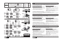
External pilot pressure supply configuration for
Series 551-552-553 threaded and NAMUR valves, with 15/16"- 26 UNS pilots
Adaptation en alimentation externe du pilotage
sur 551-552-553 taraudé et version NAMUR, avec pilotes 15/16"- 26 UNS
Anpassung der Baureihe 551-552-553 mit Gewindeanschlüssen oder NAMUR-
Aufflanschbild und 15/16" - 26 UNS-Pilotventilen auf
externe Ansteuerung
Series
Séries
Baureihe
551
552
553
IM903-09-X-R4
MONOSTABLE SOLENOID SPOOL VALVES - ELECTRODISTRIBUTEUR MONOSTABLE - MONOSTABILES MAGNETVENTIL
BISTABLE SOLENOID SPOOL VALVES - ELECTRODISTRIBUTEUR BISTABLE - BISTABILES MAGNETVENTIL
AJF/AJL: 383 45 29 AJN: 123-620-133
Rep. N.m in.Lb
a 2 17,5
b 6 52,5
TIGHTENING TORQUE
COUPLES DE SERRAGE
ANZIEHDREHMOMENTE
Fig.
Abb.
A3
552
553
551
3
2
5
6
6
5
3
3
2
3
3
2
2
3
3
3
3
2
2
3
3
3
551
552
553
5
6
5
6
5
6
5
6
a
5 mm
1
4
b
551 3mm
552-553 4mm
Pp
a
5 mm
1
4
b
Pp
551 3mm
552-553 4mm
4
3
12
1
Pp
2
5
4
12
1
2
53
10
Pp Pp
551
Pp
Pp
4
5
12
2
1
Pp
4
5
3
12
2
1
14
Pp Pp
3/2 5/2
3/2
5/2
2
3
12
1
Pp
2
3
5
14
4
12
1
Pp
1/4 -3/8 - 1/2
552
553
Pp
Pp
NAMUR
1/4 -3/8 - 1/2
1/4 -3/8 - 1/2
Fig.
Abb.
D
Fig.
Abb.
E
Fig.
Abb.
A2
Fig. /Abb. B
Fig.
Abb.
A1
Fig.
Abb.
C
I
I
II
I
II
II
I + II
Fig. /Abb. D
III
1/4 -3/8 - 1/2
NAMUR
I
II
I + II
Pilot - Commande - Ansteuerung
Pilot
Commande
Ansteuerung
Return
Rappel
Rückstellung
Pilot - Commande - Ansteuerung
Pilot
Commande
Ansteuerung
Return
Rappel
Rückstellung
INTERNA L- INTERNE
EXTERNA L- EXTERNE
INTERNAL
INTERNE
EXTERNAL
EXTERNE
threaded
taraudé
Gewindeanschlüssen
La page est en cours de chargement...
La page est en cours de chargement...
La page est en cours de chargement...
-
 1
1
-
 2
2
-
 3
3
-
 4
4


Asco Series 551 552 553 Solenoid Valves Le manuel du propriétaire
- Taper
- Le manuel du propriétaire
dans d''autres langues
- italiano: Asco Series 551 552 553 Solenoid Valves Manuale del proprietario
- English: Asco Series 551 552 553 Solenoid Valves Owner's manual
- español: Asco Series 551 552 553 Solenoid Valves El manual del propietario
- Deutsch: Asco Series 551 552 553 Solenoid Valves Bedienungsanleitung
- Nederlands: Asco Series 551 552 553 Solenoid Valves de handleiding
- português: Asco Series 551 552 553 Solenoid Valves Manual do proprietário
- dansk: Asco Series 551 552 553 Solenoid Valves Brugervejledning
- svenska: Asco Series 551 552 553 Solenoid Valves Bruksanvisning
- suomi: Asco Series 551 552 553 Solenoid Valves Omistajan opas