Lincoln Electric Red-D-Arc ZR-8 Mode d'emploi
- Catégorie
- Système de soudage
- Taper
- Mode d'emploi

RED-D-ARC
ZR-8
IM672-A
August, 2002
Red-D-Arc Spec-Built Welding Equipment
This RED-D-ARC welder is built to RED-D-ARC Extreme Duty
design specifications by Lincoln Electric.
Safety Depends on You
This welder is designed and built with safety in mind.
However, your overall safety can be increased by proper installation
... and thoughtful operation on your part.
DO NOT INSTALL, OPERATE OR REPAIR THIS EQUIPMENT
WITHOUT READING THIS MANUAL AND THE SAFETY
PRECAUTIONS CONTAINED THROUGHOUT.
And, most importantly, think before you act and be careful.
For use with machines having Code Numbers:
10706, 10938
North America’s Largest Fleet of Welding Equipment
1-800-245-3660
OPERATOR’S MANUAL

– i –
FOR ENGINE
powered equipment.
1.a. Turn the engine off before troubleshooting and maintenance
work unless the maintenance work requires it to be running.
____________________________________________________
1.b. Operate engines in open, well-ventilated
areas or vent the engine exhaust fumes
outdoors.
____________________________________________________
1.c. Do not add the fuel near an open flame
welding arc or when the engine is running.
Stop the engine and allow it to cool before
refueling to prevent spilled fuel from vaporiz-
ing on contact with hot engine parts and
igniting. Do not spill fuel when filling tank. If
fuel is spilled, wipe it up and do not start
engine until fumes have been eliminated.
____________________________________________________
1.d. Keep all equipment safety guards, covers and devices in
position and in good repair.Keep hands, hair, clothing and
tools away from V-belts, gears, fans and all other moving
parts when starting, operating or repairing equipment.
____________________________________________________
1.e. In some cases it may be necessary to remove safety
guards to perform required maintenance. Remove
guards only when necessary and replace them when the
maintenance requiring their removal is complete.
Always use the greatest care when working near moving
parts.
___________________________________________________
1.f. Do not put your hands near the engine fan.
Do not attempt to override the governor or
idler by pushing on the throttle control rods
while the engine is running.
___________________________________________________
1.g. To prevent accidentally starting gasoline engines while
turning the engine or welding generator during maintenance
work, disconnect the spark plug wires, distributor cap or
magneto wire as appropriate.
i
SAFETY
i
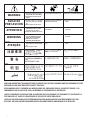
ARC WELDING CAN BE HAZARDOUS. PROTECT YOURSELF AND OTHERS FROM POSSIBLE SERIOUS INJURY OR DEATH.
KEEP CHILDREN AWAY. PACEMAKER WEARERS SHOULD CONSULT WITH THEIR DOCTOR BEFORE OPERATING.
Read and understand the following safety highlights. For additional safety information, it is strongly recommended that you
purchase a copy of “Safety in Welding & Cutting - ANSI Standard Z49.1” from the American Welding Society, P.O. Box
351040, Miami, Florida 33135 or CSA Standard W117.2-1974. A Free copy of “Arc Welding Safety” booklet E205 is available
from the Lincoln Electric Company, 22801 St. Clair Avenue, Cleveland, Ohio 44117-1199.
BE SURE THAT ALL INSTALLATION, OPERATION, MAINTENANCE AND REPAIR PROCEDURES ARE
PERFORMED ONLY BY QUALIFIED INDIVIDUALS.
WARNING
Mar ‘95
ELECTRIC AND
MAGNETIC FIELDS
may be dangerous
2.a. Electric current flowing through any conductor causes
localized Electric and Magnetic Fields (EMF). Welding
current creates EMF fields around welding cables and
welding machines
2.b. EMF fields may interfere with some pacemakers, and
welders having a pacemaker should consult their physician
before welding.
2.c. Exposure to EMF fields in welding may have other health
effects which are now not known.
2.d. All welders should use the following procedures in order to
minimize exposure to EMF fields from the welding circuit:
2.d.1.
Route the electrode and work cables together - Secure
them with tape when possible.
2.d.2. Never coil the electrode lead around your body.
2.d.3. Do not place your body between the electrode and
work cables. If the electrode cable is on your right
side, the work cable should also be on your right side.
2.d.4. Connect the work cable to the workpiece as close as
possible to the area being welded.
2.d.5. Do not work next to welding power source.
1.h. To avoid scalding, do not remove the
radiator pressure cap when the engine is
hot.
CALIFORNIA PROPOSITION 65 WARNINGS
Diesel engine exhaust and some of its constituents
are known to the State of California to cause can-
cer, birth defects, and other reproductive harm.
The engine exhaust from this product contains
chemicals known to the State of California to cause
cancer, birth defects, or other reproductive harm.
The Above For Diesel Engines
The Above For Gasoline Engines

– ii –
ii
SAFETY
ii
ARC RAYS can burn.
4.a. Use a shield with the proper filter and cover
plates to protect your eyes from sparks and
the rays of the arc when welding or observing
open arc welding. Headshield and filter lens
should conform to ANSI Z87. I standards.
4.b. Use suitable clothing made from durable flame-resistant
material to protect your skin and that of your helpers from
the arc rays.
4.c. Protect other nearby personnel with suitable, non-flammable
screening and/or warn them not to watch the arc nor expose
themselves to the arc rays or to hot spatter or metal.
ELECTRIC SHOCK can
kill.
3.a. The electrode and work (or ground) circuits
are electrically “hot” when the welder is on.
Do not touch these “hot” parts with your bare
skin or wet clothing. Wear dry, hole-free
gloves to insulate hands.
3.b. Insulate yourself from work and ground using dry insulation.
Make certain the insulation is large enough to cover your full
area of physical contact with work and ground.
In addition to the normal safety precautions, if welding
must be performed under electrically hazardous
conditions (in damp locations or while wearing wet
clothing; on metal structures such as floors, gratings or
scaffolds; when in cramped positions such as sitting,
kneeling or lying, if there is a high risk of unavoidable or
accidental contact with the workpiece or ground) use
the following equipment:
• Semiautomatic DC Constant Voltage (Wire) Welder.
• DC Manual (Stick) Welder.
• AC Welder with Reduced Voltage Control.
3.c. In semiautomatic or automatic wire welding, the electrode,
electrode reel, welding head, nozzle or semiautomatic
welding gun are also electrically “hot”.
3.d. Always be sure the work cable makes a good electrical
connection with the metal being welded. The connection
should be as close as possible to the area being welded.
3.e. Ground the work or metal to be welded to a good electrical
(earth) ground.
3.f.
Maintain the electrode holder, work clamp, welding cable and
welding machine in good, safe operating condition. Replace
damaged insulation.
3.g. Never dip the electrode in water for cooling.
3.h. Never simultaneously touch electrically “hot” parts of
electrode holders connected to two welders because voltage
between the two can be the total of the open circuit voltage
of both welders.
3.i. When working above floor level, use a safety belt to protect
yourself from a fall should you get a shock.
3.j. Also see Items 6.c. and 8.
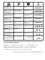
FUMES AND GASES
can be dangerous.
5.a. Welding may produce fumes and gases
hazardous to health. Avoid breathing these
fumes and gases.When welding, keep
your head out of the fume. Use enough
ventilation and/or exhaust at the arc to keep
fumes and gases away from the breathing zone. When
welding with electrodes which require special
ventilation such as stainless or hard facing (see
instructions on container or MSDS) or on lead or
cadmium plated steel and other metals or coatings
which produce highly toxic fumes, keep exposure as
low as possible and below Threshold Limit Values (TLV)
using local exhaust or mechanical ventilation. In
confined spaces or in some circumstances, outdoors, a
respirator may be required. Additional precautions are
also required when welding on galvanized steel.
5.b.
Do not weld in locations near chlorinated hydrocarbon
vapors
coming from degreasing, cleaning or spraying operations.
The heat and rays of the arc can react with solvent vapors
to
form phosgene, a highly toxic gas, and other irritating
products.
5.c. Shielding gases used for arc welding can displace air and
cause injury or death. Always use enough ventilation,
especially in confined areas, to insure breathing air is safe.
5.d. Read and understand the manufacturer’s instructions for this
equipment and the consumables to be used, including the
material safety data sheet (MSDS) and follow your
employer’s safety practices. MSDS forms are available from
your welding distributor or from the manufacturer.
5.e. Also see item 1.b.
Mar ‘95

– iii –
FOR ELECTRICALLY
powered equipment.
8.a. Turn off input power using the disconnect
switch at the fuse box before working on
the equipment.
8.b. Install equipment in accordance with the U.S. National
Electrical Code, all local codes and the manufacturer’s
recommendations.
8.c. Ground the equipment in accordance with the U.S. National
Electrical Code and the manufacturer’s recommendations.
CYLINDER may explode
if damaged.
7.a. Use only compressed gas cylinders
containing the correct shielding gas for the
process used and properly operating
regulators designed for the gas and
pressure used. All hoses, fittings, etc. should be suitable for
the application and maintained in good condition.
7.b. Always keep cylinders in an upright position securely
chained to an undercarriage or fixed support.
7.c. Cylinders should be located:
• Away from areas where they may be struck or subjected to
physical damage.
• A safe distance from arc welding or cutting operations and
any other source of heat, sparks, or flame.
7.d. Never allow the electrode, electrode holder or any other
electrically “hot” parts to touch a cylinder.
7.e. Keep your head and face away from the cylinder valve outlet
when opening the cylinder valve.
7.f. Valve protection caps should always be in place and hand
tight except when the cylinder is in use or connected for
use.
7.g. Read and follow the instructions on compressed gas
cylinders, associated equipment, and CGA publication P-l,
“Precautions for Safe Handling of Compressed Gases in
Cylinders,” available from the Compressed Gas Association
1235 Jefferson Davis Highway, Arlington, VA 22202.
iii
SAFETY
iii
Mar ‘95
WELDING SPARKS can
cause fire or explosion.
6.a.
Remove fire hazards from the welding area.
If this is not possible, cover them to prevent
the welding sparks from starting a fire.
Remember that welding sparks and hot
materials from welding can easily go through small cracks
and openings to adjacent areas. Avoid welding near
hydraulic lines. Have a fire extinguisher readily available.
6.b. Where compressed gases are to be used at the job site,
special precautions should be used to prevent hazardous
situations. Refer to “Safety in Welding and Cutting” (ANSI
Standard Z49.1) and the operating information for the
equipment being used.
6.c. When not welding, make certain no part of the electrode
circuit is touching the work or ground. Accidental contact
can cause overheating and create a fire hazard.
6.d. Do not heat, cut or weld tanks, drums or containers until the
proper steps have been taken to insure that such procedures
will not cause flammable or toxic vapors from substances
inside. They can cause an explosion even
though
they have
been “cleaned”. For information, purchase “Recommended
Safe Practices for the
Preparation
for Welding and Cutting of
Containers and Piping That Have Held Hazardous
Substances”, AWS F4.1 from the American Welding Society
(see address above).
6.e. Vent hollow castings or containers before heating, cutting or
welding. They may explode.
6.f.
Sparks and spatter are thrown from the welding arc. Wear oil
free protective garments such as leather gloves, heavy shirt,
cuffless trousers, high shoes and a cap over your hair. Wear
ear plugs when welding out of position or in confined places.
Always wear safety glasses with side shields when in a
welding area.
6.g. Connect the work cable to the work as close to the welding
area as practical. Work cables connected to the building
framework or other locations away from the welding area
increase the possibility of the welding current passing
through lifting chains, crane cables or other alternate cir-
cuits. This can create fire hazards or overheat lifting chains
or cables until they fail.
6.h. Also see item 1.c.

– iv –
iv
SAFETY
iv
PRÉCAUTIONS DE SÛRETÉ
Pour votre propre protection lire et observer toutes les instruc-
tions et les précautions de sûreté specifiques qui parraissent
dans ce manuel aussi bien que les précautions de sûreté
générales suivantes:
Sûreté Pour Soudage A L’Arc
1. Protegez-vous contre la secousse électrique:
a. Les circuits à l’électrode et à la piéce sont sous tension
quand la machine à souder est en marche. Eviter toujours
tout contact entre les parties sous tension et la peau nue
ou les vétements mouillés. Porter des gants secs et sans
trous pour isoler les mains.
b. Faire trés attention de bien s’isoler de la masse quand on
soude dans des endroits humides, ou sur un plancher
metallique ou des grilles metalliques, principalement dans
les positions assis ou couché pour lesquelles une
grande partie du corps peut être en contact avec la
masse.
c. Maintenir le porte-électrode, la pince de masse, le câble
de soudage et la machine à souder en bon et sûr état
defonctionnement.
d.Ne jamais plonger le porte-électrode dans l’eau pour le
refroidir.
e. Ne jamais toucher simultanément les parties sous tension
des porte-électrodes connectés à deux machines à soud-
er parce que la tension entre les deux pinces peut être le
total de la tension à vide des deux machines.
f. Si on utilise la machine à souder comme une source de
courant pour soudage semi-automatique, ces precautions
pour le porte-électrode s’applicuent aussi au pistolet de
soudage.
2. Dans le cas de travail au dessus du niveau du sol, se pro-
téger contre les chutes dans le cas ou on recoit un choc. Ne
jamais enrouler le câble-électrode autour de n’importe quelle
partie du corps.
3. Un coup d’arc peut être plus sévère qu’un coup de soliel,
donc:
a. Utiliser un bon masque avec un verre filtrant approprié
ainsi qu’un verre blanc afin de se protéger les yeux du
rayonnement de l’arc et des projections quand on soude
ou quand on regarde l’arc.
b. Porter des vêtements convenables afin de protéger la
peau de soudeur et des aides contre le rayonnement de
l‘arc.
c. Protéger l’autre personnel travaillant à proximité au
soudage à l’aide d’écrans appropriés et non-inflamma-
bles.
4. Des gouttes de laitier en fusion sont émises de l’arc de
soudage. Se protéger avec des vêtements de protection
libres de l’huile, tels que les gants en cuir, chemise épaisse,
pantalons sans revers, et chaussures montantes.
5. Toujours porter des lunettes de sécurité dans la zone de
soudage. Utiliser des lunettes avec écrans lateraux dans les
zones où l’on pique le laitier.
6. Eloigner les matériaux inflammables ou les recouvrir afin de
prévenir tout risque d’incendie dû aux étincelles.
7. Quand on ne soude pas, poser la pince à une endroit isolé de
la masse. Un court-circuit accidental peut provoquer un
échauffement et un risque d’incendie.
8. S’assurer que la masse est connectée le plus prés possible
de la zone de travail qu’il est pratique de le faire. Si on place
la masse sur la charpente de la construction ou d’autres
endroits éloignés de la zone de travail, on augmente le risque
de voir passer le courant de soudage par les chaines de lev-
age, câbles de grue, ou autres circuits. Cela peut provoquer
des risques d’incendie ou d’echauffement des chaines et des
câbles jusqu’à ce qu’ils se rompent.
9. Assurer une ventilation suffisante dans la zone de soudage.
Ceci est particuliérement important pour le soudage de tôles
galvanisées plombées, ou cadmiées ou tout autre métal qui
produit des fumeés toxiques.
10. Ne pas souder en présence de vapeurs de chlore provenant
d’opérations de dégraissage, nettoyage ou pistolage. La
chaleur ou les rayons de l’arc peuvent réagir avec les
vapeurs du solvant pour produire du phosgéne (gas forte-
ment toxique) ou autres produits irritants.
11. Pour obtenir de plus amples renseignements sur la sûreté,
voir le code “Code for safety in welding and cutting” CSA
Standard W 117.2-1974.
PRÉCAUTIONS DE SÛRETÉ POUR
LES MACHINES À SOUDER À
TRANSFORMATEUR ET À
REDRESSEUR
1. Relier à la terre le chassis du poste conformement au code
de l’électricité et aux recommendations du fabricant. Le dis-
positif de montage ou la piece à souder doit être branché à
une bonne mise à la terre.
2. Autant que possible, I’installation et l’entretien du poste
seront effectués par un électricien qualifié.
3. Avant de faires des travaux à l’interieur de poste, la
debrancher à l’interrupteur à la boite de fusibles.
4. Garder tous les couvercles et dispositifs de sûreté à leur
place.
Mar. ‘93

– v –
Thank You
for selecting a QUALITY product. We want you to take pride in
operating this product ••• as much pride as we have in bringing
this product to you!
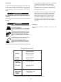
Read this Operators Manual completely before attempting to use this equipment. Save this manual and keep it
handy for quick reference. Pay particular attention to the safety instructions we have provided for your protection.
The level of seriousness to be applied to each is explained below:
WARNING
This statement appears where the information must be followed exactly to avoid serious personal injury or
loss of life.
This statement appears where the information must be followed to avoid minor personal injury or damage to
this equipment.
CAUTION
Please Examine Carton and Equipment For Damage Immediately
When this equipment is shipped, title passes to the purchaser upon receipt by the carrier. Consequently, Claims
for material damaged in shipment must be made by the purchaser against the transportation company at the
time the shipment is received.
Please record your equipment identification information below for future reference. This information can be
found on your machine nameplate.
Model Name & Number _____________________________________
Code & Serial Number _____________________________________
Date of Purchase _____________________________________
Whenever you request replacement parts for or information on this equipment always supply the information
you have recorded above.
vv

– vi –
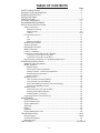
TABLE OF CONTENTS
Page
SAFETY PRECAUTIONS ........................................................................................i-iv
INTRODUCTORY INFORMATION ...........................................................................vii
GENERAL DESCRIPTION ........................................................................................7
DESIGN FEATURES .................................................................................................7
SPECIFICATIONS...................................................................................................8-10
OPTIONAL EQUIPMENT..........................................................................................11
RECOMMENDED EQUIPMENT...............................................................................12
INSTALLATION INSTRUCTIONS.............................................................................13
Safety Precautions..............................................................................................13
Machine Grounding ......................................................................................13
Spark Arrester ..............................................................................................13
Trailers.......................................................................................................13-14
Pre-Operation Service ........................................................................................14
Oil .................................................................................................................14
Fuel ..............................................................................................................14
Battery Connection.......................................................................................14
Welding Output Cables.......................................................................................14
Angle of Operation..............................................................................................15
High Altitude Operation.......................................................................................15
Muffler Relocation...............................................................................................15
Location / Ventilation ..........................................................................................15
Connection of Lincoln Electric Wire Feeders......................................................15
Connection of the LN-25 to the ZR-8 ...........................................................15
Connection of the LN-7 to the ZR-8 .............................................................16
High Frequency Generator for TIG Welding Applications...................................16
OPERATING INSTRUCTIONS .................................................................................16
Additional Safety Precautions.............................................................................16
Welder Operation................................................................................................16
Welder Output ..............................................................................................16
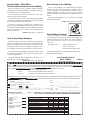
ZR-8 Typical Fuel Consumption...................................................................16
Welder Controls - Function and Operation...................................................17
Start/Shutdown Instructions .........................................................................17
Break-in Period.............................................................................................18
Welding Process.................................................................................................18
Stick (Constant Current) Welding.................................................................18
TIG (Constant Current) Welding...................................................................18
Wire Feed Welding Processes (Constant Voltage) ......................................19
Summary of Welding Process ......................................................................19
Auxiliary Power ...................................................................................................20
Electrical Device use with the ZR-8............................................................. 21
Auxiliary Power While Welding.....................................................................22
Standby Power Connection..........................................................................22
Connecting ZR-8 to Premises Wiring .................................................................23
MAINTENANCE ........................................................................................................24
Safety Precautions..............................................................................................24
Routine Maintenance..........................................................................................24
Engine Adjustments............................................................................................24
Slip Rings............................................................................................................25
Battery ................................................................................................................25
Hardware ............................................................................................................25
Engine Maintenance Parts..................................................................................25
TROUBLESHOOTING ...........................................................................................26-27
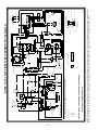
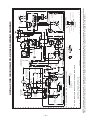
Wiring Diagram.................................................................................................28,29
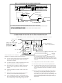
Connection Diagrams .........................................................................................30
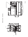
Dimension Print ..................................................................................................31
PARTS PAGES .................................................................................................P229 Series

– 7 –– 7 –
GENERAL DESCRIPTION
The ZR-8 is a twin-cylinder, gasoline driven, multi-
process arc welder and AC power generator. It is built
in a heavy gauge steel case for durability on the job
site.
DESIGN FEATURES
AC/DC STICK WELDING (Constant Current)
• AC 40 - 225 Amps
• DC 40 - 210 Amps
• 100% Duty Cycle on All Settings
• Output Selector with 6 Ranges
• Output Control for Fine Current Adjustment
• Use with a broad range of AC & DC Electrodes
Including Fleetweld® 5P
DC SEMIAUTOMATIC WIRE FEED WELDING
(Constant Voltage)
• CV Tap Setting for 60-200 Amps.
• 100% Duty Cycle.
• Excellent Performance with .068” (1.7mm)
NR®-211-MP Innershield® Electrode.
•
Limited MIG Welding with L-50 & L-56 using blended
Argon Shielding Gas.
• The Recommended Wire Feeder is the LN-25, but
Can Also be Used with the LN-7 Wire Feeder.
(LN-7 and LN-25 without Contactor Requires the
K240 Contactor Kit).
AC/DC TIG WELDING (Constant Current)
• AC & DC TIG Welding Can be Done at All Constant
Current Output Range Settings.
AUXILIARY POWER
• 8000 Watt AC 115/230 Volt 60 Hz. Generator.
• Operates AC Power Tools.
• Powers Battery Chargers.
• Powers a 1.5 HP Motor (If Started Under No Load).
• Lights Eighty 100 Watt Incandescent Bulbs.
• Can be Used for Standby Power.
OTHER FEATURES
• Bottom Mounted 9 Gallon Fuel Tank with a
Convenient Top Fill and Fuel Gauge.
• Polarity Switch for Selecting DC+, DC-, or AC
Welding Output.
• K930-1 TIG Module Available.
• Remote Control Receptacle Kit Available.
•
Electronic Engine Idler. Engine Automatically Goes to
Low Idle in 10 to 14 Seconds after Welding or Use
of Auxiliary Power. Includes High Idle Switch.
• Electric Starting.
• Battery Charging Ammeter.
• Full 8 kVA Auxiliary Output Receptacle.
• Factory Installed Engine Hour Meter.
• Engine Protection Shuts Engine Down in the
Event of Low Oil Pressure.
• Built-in Feet for Easy Mounting to Truck Bed or
Trailer.
• All Copper Alternator Windings and High
Quality Insulation for Long-Life and
Dependability.
• Powder Painted Case and Base for Outstanding
Corrosion Protection.
• Quiet muffler with reversible exhaust feature; either
right or left side of machine.
ENGINE
The Kohler 18 HP Command®* engine has the follow-
ing features:
• Air Cooled, Twin-Cylinder.
• Cast Aluminum Alloy Crankcase with Integral Cast
Iron Cylinder Liners.
• Electric Start with Solid State Battery Charging
Module.
• Solid State Breakerless Ignition.
• Spin on Oil Filter.
• Low Oil Pressure Shutdown Protection.
Overhead valves and hydraulic valve lifters.
* The trademark is the property of their respective
manufacturer.

– 8 –
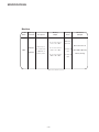
Machine
Product
Name
Ordering
Information
K1786-1
K1786-4
Description
Multi-Purpose
Arc Welder with
8,000 watts of
Auxiliary Power
AC Constant Current
225A / 25V / 100%
DC Constant Current
210A / 25V / 100%
DC Constant Voltage
200A / 20V / 100%
Auxiliary
Power
Welding
Output
8000 Watts,
60 Hz AC
70 Amps @
115V
35 Amps @
230V
Dimensions
& Weight
30.3 x 19.2 x 42.3 in
(765 x 460 x 1073 mm)
511 lbs (233 kg)
* Based on a 10 min. period.
ZR-8
SPECIFICATIONS

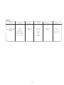
– 9 –
2 Cylinder
4 Cycle
Air-Cooled
Gasoline Engine.
Aluminum Alloy with
Cast Iron Liners,
Electrical Ignition
Full Load:
3500 RPM
High Idle:
3700 RPM
Low Idle:
2200 RPM
Product
Name Description Horsepower
Operating
Speeds Displacement Capacities
Engine
ZR-8
(Kohler Command
CH20S)
20 HP
@ 3600 RPM
38.1 cu in
(624 cc)
Fuel:
9 Gal (34 L)
Lubricating Oil:
2.0 Qts (1.9 L)

– 10 –
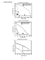
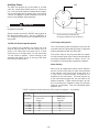
AC STICK / TIG (CC) OUTPUT
A 225 OUTPUT RANGE
B 50 OUTPUT RANGE
A
B
OUTPUT AMPS
OUTPUT VOLTS AC (RMS)
0
50 100 150 200
250
0
10
20
30
40
50
60
70
80
DC STICK / TIG (CC) OUTPUT
OUTPUT AMPS
OUTPUT VOLTS DC (RMS)
A 210 OUTPUT RANGE
B 50 OUTPUT RANGE
A
B
0
50 100 150
200 250 300
350
0
10
20
30
40
50
60
70
80
CV OUTPUT RANGE
0
50
100
150
200
250 300
OUTPUT AMPS
350
0
5
10
15
20
25
30
35
40
DC WIRE FEED (CV) OUTPUT
OUTPUT VOLTS DC (RMS)
SPECIFICATIONS

– 11 –
OPTIONAL EQUIPMENT (Field Installed)
Two-Wheel Trailer (K768-2) - For in-plant and yard
towing. (For highway use, consult applicable federal,
state, and local laws regarding possible requirements
for brakes, lights, fenders, etc.)
Two-Wheel Undercarriage (K889-2) - For moving by
hand. Overall Width 29 in (.74m)
Caster for Undercarriage (K893-1) - Mounts to the
front of the K889-2 to allow easy movement on
smooth surfaces. Includes 6” diameter hard rubber
wheel and convenient toe-on, toe-off locking brake.
Canvas Cover (K886-1) - To protect the ZR-8 when
not in use. Made from attractive red canvas material
which is flame retardant, mildew resistant, and water
repellent.
Power Plug Kit (K802-N) - Provides four 115V plugs
rated at 20 amps each and one dual voltage, full kVA
plug rated at 115/230V, 50 amps.
Power Plug Kit (K802-R) - Provides four 115V plugs
rated at 15 amps each and one dual voltage, full kVA
plug rated at 115/230V, 50 amps.
Accessory Kit (K710) - Includes 30 ft (9.1m) 3 AWG
electrode cable, 25 ft. (7.6m) 3 AWG work cable,
headshield with No. 12 filter, GC300 work clamp and
Cooltong® 300 electrode holder. Cables are rated at
225 amps, 40% duty cycle.
Remote Control Receptacle Kit (K892-1) - Includes
a 6-pin MS-type (Amphenol) receptacle and a local-
remote toggle switch that mounts in the case front.
Requires a Remote Control Option.
Remote Control (K857) - Consists of a control box
with 25 ft. (7.5m) of four conductor cable. Permits
remote adjustment of output voltage. (Requires
Remote Control Receptacle Kit to be mounted in
machine.)
Spark Arrester Kit (K894-1) - Includes a heavy
gauge steel, approved spark arrester and clamp for
easy mounting to muffler exhaust pipe.
GFCI Receptacle Kit (K896-1) - Includes two UL
approved 115V ground fault circuit interrupter duplex
type receptacles with covers and installation instruc-
tions. Replaces the two factory installed 115V duplex
receptacles. Each receptacle of each GFCI duplex is
rated at 15 amps, but the maximum total current from
each GFCI duplex is limited to 20 amps.
TIG Module (K930-1) - Provides high frequency and
shielding gas control for AC and DC GTAW (TIG)
welding applications. Its compact case is designed for
easy carrying, complete with a handle. High frequen-
cy bypass is built in. The K938-1 Contactor Kit must
be field installed in the TIG Module when used with a
ZR-8. Additionally, the K936-3 control cable is
required if remote control is used. If remote control is
not used the K936-4 control cable is required.
Remote Control Cable (K936-3) - Control cable for
connecting the K930-1 TIG Module to a ZR-8
equipped with a K892-1 Remote Kit. 9-Socket to a
grounded 115 V plug and a 6 pin MS-connector.
(Contains circuits 2, 4, 31, 32, 75, 76, 77 and ground)
Remote Control Cable (K936-4) - Control cable for
connecting the K930-1 TIG Module to a ZR-8 not
equipped with a K892-1 Remote Kit. 9-Socket to a
grounded 115 V plug and a 6 pin MS-connector.
(Contains circuits 31, 32, and ground)
Docking Kit (K939-1) - For mounting the K930-1 TIG
Module unit on top of the ZR-8.
Remote Control Receptacle Kit (K892-1) - Required
when using a K930-1 TIG Module with and optional
amptrol.

RECOMMENDED EQUIPMENT
STICK
Accessory Kit (K710) which includes:
• Electrode Holder & Cable
• Work Clamp & Cable
• Headshield
Remote Control Receptacle Kit (K892-1), and Remote
Control Kit (K857) are optional for remote current
control.
TIG
Magnum™ TIG Torch
Magnum Parts Kit and Argon Gas
TIG Module (K930-1) (requires K938-1 Contactor Kit)
Control Cable K939-3 or K939-4 (see Optional
Equipment)
Optional:
• Docking Kit (K939-1)
• Hand Amptrol® (K963)
• Foot Amptrol (K870)
• Remote Control Receptacle Kit (K892-1)
• Adapter Cable (K915-1)
WIRE
FEED
LN-25 (K449) - Includes internal contactor for across
the arc operation (no control cable). Provides “cold”
electrode until gun trigger is pressed. Includes gas
solenoid. Remote control Receptacle Kit (K892-1)
and Remote voltage Control Kit (K444-1) are required
for voltage control at the feeder.
LN-7 - Contactor Kit (K240) is required.
Magnum Gun is required for gas-shielded welding.
Innershield Gun is required for gasless welding.
– 12 –

– 13 –
INSTALLATION INSTRUCTIONS
Safety Precautions
Machine Grounding
Because this portable engine driven welder or gener-
ator creates it’s own power, it is not necessary to con-
nect it’s frame to an earth ground, unless the
machine is connected to premises wiring (your home,
shop, etc.).
To prevent dangerous electric shock, other equip-
ment to which this engine driven welder supplies
power must:
a. be grounded to the frame of the welder using a
grounded type plug, or
b. be double insulated.
When this welder is mounted on a truck or trailer, it’s
frame must be securely connected to the metal frame
of the vehicle.
Where this engine driven welder is connected to
premises wiring such as that in your home or shop,
it’s frame must be connected to the system earth
ground. See further connection instructions in the
section entitled “Standby Power Connections”, as well
as the article on grounding in the latest U.S. National
Electrical Code and the local code.
In general, if the machine is to be grounded, it should
be connected with a #8 or larger copper wire to a solid
earth ground such as a metal water pipe going into
the ground for at least ten feet and having no insulat-
ed joints, or to the metal framework of a building
which has been effectively grounded. The U.S.
National Electrical Code lists a number of alternate
means of grounding electrical equipment. A machine
grounding stud marked with the symbol is provid-
ed on the front of the welder.
Spark Arrester
Some federal, state, or local laws may require that
gasoline engines be equipped with exhaust spark
arresters when they are operated in certain locations
where unarrested sparks may present a fire hazard.
The standard muffler included with this welder does
not qualify as a spark arrester. When required by
local regulations, the K894-1 spark arrester must be
installed and properly maintained.
An incorrect arrester may lead to damage to the
engine or adversely affect performance.
Trailers
The recommended trailer for use with this equipment
for in plant and yard towing by a vehicle is Lincoln’s
K768-2. Consult applicable federal, state, and local
laws regarding specific requirements for use on public
highways.
If the user adapts a non-Lincoln trailer, he must
assume responsibility that the method of attachment
and usage does not result in a safety hazard nor dam-
age the welding equipment.
CAUTION
Do not attempt to use this equipment until you
have thoroughly read the engine manufacturer’s
manual supplied with your welder. It includes
important safety precautions, detailed engine
starting, operating and maintenance instructions,
and parts lists.
------------------------------------------------------------------------
ELECTRIC SHOCK can kill.
• Do not touch electrically live parts or
electrode with skin or wet clothing.
• Insulate yourself from work and
ground
• Always wear dry insulating gloves.
------------------------------------------------------------------------
ENGINE EXHAUST can kill.
• Use in open, well ventilated areas or
vent exhaust outside.
------------------------------------------------------------------------
MOVING PARTS can injure.
• Do not operate with doors open or
guards off.
• Stop engine before servicing.
• Keep away from moving parts.
------------------------------------------------------------------------
See additional warning information at
front of this operator’s manual.
-----------------------------------------------------------
WARNING

– 14 –
Some of the factors to be considered are as follows:
1. Design capacity of trailer vs. weight of Lincoln
equipment and likely additional attachments.
2. Proper support of, and attachment to, the base of
the welding equipment so there will be no undue
stress to the framework.
Pre-Operation Service
READ the engine operating and maintenance instruc-
tions supplied with this machine.
Oil
The ZR-8 is shipped with the engine crankcase filled
with SAE 10W-30 oil. Check the oil level before start-
ing the engine. If it is not up to the full mark on the dip
stick, add oil as required. Make certain that the oil
filler cap is tightened securely. Refer to the engine
Owner’s Manual for specific oil recommendations.
Fuel
Fill the fuel tank with clean, fresh, lead-free gasoline.
Observe fuel gauge while filling to prevent overfilling.
Battery Connections
This welder is shipped with the negative battery cable
disconnected. Make sure that the Engine Switch is in
the “STOP” position and attach the disconnected
cable securely to the negative battery terminal before
attempting to operate the machine. If the battery is
discharged and does not have enough power to start
the engine, see the battery charging instructions in the
Battery section.
Welding Output Cables
With the engine off, connect the electrode and work
cables to the studs provided. These connections
should be checked periodically and tightened if neces-
sary. Loose connections will result in overheating of
the output studs.
When welding at a considerable distance from the
welder, be sure you use ample size welding cables.
Listed below are copper cable sizes recommended for
the rated current and duty cycle. Lengths stipulated
are the distance from the welder to work and back to
the welder again. Cable sizes are increased for
greater lengths primarily for the purpose of minimizing
cable voltage drop.
CAUTION
GASOLINE
fuel can cause fire or
explosion.
-
• Stop engine while fueling.
• Do not smoke when fueling.
• Do not overfill tank.
• Keep sparks and flame away from tank.
• Wipe up spilled fuel and allow fumes to clear
before starting engine.
------------------------------------------------------------------------
WARNING
TOTAL COMBINED LENGTH OF
ELECTRODE AND WORK CABLES
0-50 Ft.
50-100 Ft.
100-150 Ft.
150-200 Ft.
200-250 Ft.
225 Amps
40% Duty Cycle
3 AWG
3 AWG
2 AWG
1 AWG
1/0 AWG
225 Amps
100% Duty Cycle
1 AWG
1 AWG
1 AWG
1 AWG
1/0 AWG
LUBRICATION SYSTEM CAPACITY
(INCLUDING FILTER)
Kohler CH20S - 2.0 Quarts (1.9 Liters)

– 15 –
Angle of Operation
Internal combustion engines are designed to run in a
level condition which is where the optimum perfor-
mance is achieved. The maximum angle of operation
for the engine is 15 degrees from horizontal in any
direction. If the engine is to be operated at an angle,
provisions must be made for checking and maintain-
ing the oil at the normal (FULL) oil capacity in the
crankcase in a level condition.
When operating at an angle, the effective fuel capaci-
ty will be slightly less than the specified 10 gallons.
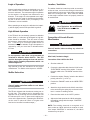
High Altitude Operation
If the ZR-8 will be consistently operated at altitudes
above 5000 ft, a carburetor jet designed for high alti-
tudes should be installed. This will result in better
fuel economy, cleaner exhaust, and longer spark plug
life. It will not
give increased power which is
decreased at higher altitudes. Engine horsepower is
reduced by 3.5% per 1000 feet for altitudes above
377 feet.
Do not operate a ZR-8 with a high altitude jet
installed at altitudes below 5000 ft. This will
result in the engine running too lean and result in
higher engine operating temperatures which can
shorten engine life.
High altitude jet kits are available from the engine
manufacturer. For Kohler order kit part no. 2475501.
Muffler Relocation
Shut off welder and allow muffler to cool before
touching muffler.
The ZR-8 is shipped with the exhaust coming out on
the left side. The exhaust can be changed to the
opposite side by removing the two screws that hold
the exhaust port cover in place and installing the
cover on the opposite side. (Operating the ZR-8 with-
out the cover in place will result in a higher noise
level and no increase in machine output.)
Location / Ventilation
The welder should be located to provide an unrestrict-
ed flow of clean, cool air to the cooling air inlets and to
avoid heated air coming out of the welder recirculating
back to the cooling air inlet. Also, locate the welder
so that engine exhaust fumes are properly vented to
an outside area.
Connection of Lincoln Electric
Wire Feeders
Shut off welder before making any electrical
connections.
Wire Feed (Constant voltage)
Connection of the LN-25 to the ZR-8
a. Shut the welder off.
b.
Connect the electrode cable from the LN-25 to the
“ELECTRODE” terminal of the welder. Connect
the work cable to the “TO WORK” terminal of the
welder.
c. Position the welder “Polarity” switch to the desired
polarity, either DC (-) or DC (+).
d. Position the “RANGE” switch to the “WIRE FEED”
position.
e. Attach the single lead from the LN-25 control box
to the work using the spring clip on the end of the
lead - it carries no welding current.
f. Place the idler switch in the “AUTO” position.
g. Adjust wire feed speed at the LN-25 and adjust
the welding voltage with the output “CONTROL”
at the welder.
NOTE: The welding electrode is energized at all
times, unless an LN-25 with built-in contactor is used.
If the output “CONTROL” is set below “3”, the LN-25
contactor may not pull in.
CAUTION
WARNING
• Damage to the fuel tank may cause
fire or explosion. Do not drill holes
in the ZR-8 base or weld to the
ZR-8 base.
WARNING
WARNING

– 16 –
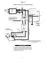
Connection of the LN-7 to the ZR-8
a. Shut the welder off.
b. Connect the LN-7 and the K240 contactor kit per
instructions on the connection diagram S17742
(can be found in the back of this manual).
c. Place the “RANGE” switch to the “WIRE FEED”
position and the “POLARITY” switch to the
desired polarity.
d. Place the “IDLER” switch in the “HIGH” idle
position. The engine idling device may not
function when welding in the “WIRE FEED” mode.
e. Adjust wire feed speed at the LN-7 and adjust the
welding voltage with the output “CONTROL” at
the welder.
NOTE: If the output “CONTROL” is set below “3” the
K240 contactor may not pull in.
Connection of K930-1 TIG Module to the
ZR-8.
The TIG Module is an accessory that provides high
freqency and shielding gas control for AC and DC
GTAW (TIG) welding. See IM528 supplied with the
TIG Module for installation instructions.
Note: The TIG Module does not require the use of a
high frequency bypass capacitor. However, if the ZR-
8 is used with any other high frequency equipment,
the bypass capacitor must be installed - order kit
T12246.
OPERATING
INSTRUCTIONS
Additional Safety Precautions
Always operate the welder with the roof and case
sides in place as this provides maximum protection
from moving parts and assures proper cooling air flow.
Read and understand all Safety Precautions before
operating this machine. Always follow these and any
other safety procedures included in this manual and in
the Engine Owner’s Manual.
Welder Operation
Welder Output
• Maximum Open Circuit Voltage at 3700 RPM is
80 Volts RMS.
• Duty Cycle: 100% for both welding and auxiliary
power.
ZR-8
Constant Current 225 Amps AC @ 25 Volts
210 Amps DC @ 25 Volts
Constant Voltage 200 Amps DC @ 20 Volts
Low Idle - No Load
2200 RPM
High Idle - No Load
3700 RPM
AC CC Weld Output
225 Amps @ 25 Volts
DC CC Weld Output
210 Amps @ 25 Volts
DC CV Weld Output
200 Amps @ 20 Volts
Auxiliary Power
8000 Watts
KOHLER
20 H.P. COMMAND
.4 Gallons/Hour
(1.5 Liters/Hour)
.9 Gallons/Hour
(3.5 Liters/Hour)
1.3 Gallons/Hour
(5.0 Liters/Hour)
1.4 Gallons/Hour
(5.3 Liters/Hour)
1.2 Gallons/Hour
(4.5 Liters/Hour)
1.4 Gallons/Hour
(5.3 Liters/Hour)
ZR-8 Approximate Fuel Consumption

– 17 –
Welder Controls - Function and Operation
ENGINE “ON-OFF” Switch
When placed in the “ON” position, this switch
energizes the engine ignition circuit. When placed in
the “OFF” position, the ignition circuit is de-energized
to shut down the engine.
ENGINE “START” Push-Button Switch
Energizes engine starter motor.
“Polarity” Switch
Never change the “Polarity” switch setting while
welding. This will damage the switch.
“ Range” Switch
Never change the “RANGE” Switch setting while
welding. This will damage the switch.
“
Control” Switch
Provides a fine welding current adjustment within the
Range Switch settings in the STICK/TIG mode and
welding voltage control with the Range switch set in
the wire feed mode.
“IDLER” Switch
The idler switch has two positions, “HIGH” and
“AUTO”.
When in “HIGH” ( ) position, the engine will run
continuously at high idle.
When in “AUTO” ( / ) idle position, the idler
operates as follows:
a. Welding
When the electrode touches the work, the welding
arc is initiated and the engine accelerates to full
speed.
After welding ceases (and no auxiliary power is
being drawn), the engine will return to low idle
after approximately 10 to 14 seconds.
b. Auxiliary Power
With the engine running at low idle and auxiliary
power for lights or tools is drawn (approximately
100-150 watts or greater) from the receptacles,
the engine will accelerate to high speed. If no
power is being drawn from the receptacles (and
not welding) for 10-14 seconds, the idler reduces
the engine speed to low idle.
Starting/Shutdown Instructions
Starting the Engine
Be sure all Pre-Operation Maintenance has been per-
formed. Also, read the Engine Owner’s Manual.
Remove all loads connected to the AC power recepta-
cles. To start the engine, set the “Idler Control” switch
in the Automatic ( / ) position.
Use the choke control as follows:
CAUTION
STICK/TIG - CC 50, 70, 90
6 Range Settings 125, 175, 210 DC/225 AC
WIRE FEED - CV
1 Range Setting 200
CAUTION
• Do not touch electrically live parts
of electrode with skin or wet
clothing.
• Keep flammable material away.
• Insulate yourself from work and
ground. Wear eye, ear, and body
protection.
• Keep your head out of the fumes.
• Use ventilation or exhaust to
remove fumes from breathing zone.
WARNING
Process Maximum Current
on Each Setting
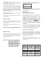
ON
OFF
Explanation of Symbols that Appear on this Equipment
Low Idle
High Idle

– 18 –
Kohler Engine - Always pull the choke control out
when starting the engine; cold, warm or hot. Place the
“Engine” switch in the “ON” position.
Push the “START” button and crank the engine until it
starts. Release the button as soon as the engine
starts. Do not push the “START” button while the
engine is running because this will cause damage to
the ring gear and/or starter motor. After the engine
has started, slowly return the choke control to the full
“in” position (choke open).
After running at high engine speed for 10-14 seconds,
the engine will go to low idle.
Allow the engine to warm up by letting it run at low idle
for a few minutes.
Stopping the Engine
Remove all welding and auxiliary power loads and
allow engine to run at low idle speed for a few minutes
to cool the engine.
Stop the engine by placing the “Engine” switch in the
“OFF” position.
A fuel shut off valve is not required on the ZR-8
because the fuel tank is mounted below the engine.
Break-in Period
It is normal for any engine to use a greater amount of
oil until the break-in is accomplished. Check the oil
level twice a day during the break-in period (approxi-
mately 50 running hours)).
IMPORTANT: IN ORDER TO ACCOMPLISH THIS
BREAK-IN, THE UNIT SHOULD BE
SUBJECTED TO MODERATE
LOADS, WITHIN THE RATING OF
THE MACHINE. AVOID LONG IDLE
RUNNING PERIODS. REMOVE
LOADS AND ALLOW ENGINE TO
COOL BEFORE SHUTDOWN.
The engine manufacturer’s recommendation for the
running time until the first oil change is as follows:
The oil filter is to be changed at the second oil
change. Refer to the Engine Owner’s Manual for
more information.
Welding Process
Stick (Constant Current) Welding
Connect welding cables to the "TO WORK” and
"ELECTRODE” studs. Start the engine. Set the
"Polarity” switch to the desired polarity. Set the
“RANGE” switch to a setting that is equal to or slightly
greater than the desired welding current. (The
“RANGE” dial marking indicates the maximum
current
for that range). Fine adjustment of the welding current
is made by adjusting the output “CONTROL” or
remote control. For best arc stability, use settings
5 through 10.
The ZR-8 can be used with a broad range of AC and
DC stick electrodes. See “Welding Tips 1” included
with the ZR-8 for electrodes within the rating of this
unit and recommended welding currents of each.
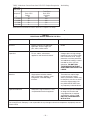
TIG (Constant Current) Welding
The K930-1 TIG Module installed on a ZR-8 provides
high frequency and shielding gas control for AC and
DC GTAW (TIG) welding processes. The TIG Module
allows full range output control. Afterflow time is
adjustable from 0 to 55 seconds.
When using the ZR-8 for AC TIG welding of alu-
minum, the following settings and electrodes are
recommended:
Kohler
CH20S
5 hr
SETTINGS FOR PURE TUNGSTEN
TUNGSTEN RANGE SWITCH APPROXIMATE
DIAMETER (in.) SETTINGS CURRENT RANGE
1/8 70, 90, or 125 80 - 150 Amps
3/32 50, 70, or 90 45 - 130 Amps
1/16 50, or 70 40 - 80 Amps
SETTINGS FOR 1% THORIATED TUNGSTEN
TUNGSTEN RANGE SWITCH APPROXIMATE
DIAMETER (in.) SETTINGS CURRENT RANGE
1/8 70, 90, 125, or 175 80 - 225 Amps
3/32 50, 70, 90, or 125 50 - 180 Amps
1/16 50, 70, or 90 45 - 120 Amps

– 19 –
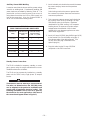
Wire Feed Welding Processes
(Constant Voltage)
The only Innershield
®
electrode recommended for use
with the ZR-8 is NR
®
-211-MP. The electrode sizes
and welding ranges that can be used with the ZR-8
are shown in the following table:
Diameter Wire Speed Approximate
(in.) Range In./Min. Current Range
.035 80 - 110 75A to 120A
.045 70 - 130 120A to 170A
.068 40 - 90 125A to 210A
The ZR-8 is recommended for limited “MIG” welding
(GMAW - gas metal arc welding). The recommended
electrodes are .030” and .035” L-50 and L-56. They
must be used with a blended shielding gas such as
C25 (75% Argon - 25% CO
2
). The welding ranges
that can be used with the ZR-8 are shown in the fol-
lowing table:
Diameter Wire Speed Approximate
(in.) Range In./Min. Current Range
.030 80 - 110 75A to 120A
.035 70 - 130 120A to 170A
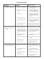
Summary of Welding Processes
CONTROL ELECTRODE
CABLE IDLE WHEN NOT TO START
PROCESS USED MODE WELDING WELDING
STICK No AUTO Hot Touch electrode to work.
Welding starts immediately
and engine goes to high
idle.
TIG/K7930-1/K938-1, Yes HIGH Cold Press Amptrol, contactor
K936-( ) /K892-1 closes, welding
(WITH AMPTROL) starts immediately.
WIRE FEED, LN-25 WITH No AUTO Cold Press gun trigger, LN-25
INTERNAL CONTACTOR contactor closes. Welding
starts immediately and
engine goes to high idle.
NOTE: Output Control
must be set above “3”.
WIRE FEED, LN-7 WITH Yes HIGH Cold Press gun trigger,
K240 CONTACTOR KIT contactor closes. Welding
starts immediately.
The K930-1 TIG Module should be used with the ZR-
8 on high idle to maintain satisfactory operation. It can
be used in the AUTO position but the delay going to
flow idle after welding is ceased will be increased if
the AFTERFLOW CONTROL is set above 10 sec-
onds
La page est en cours de chargement...
La page est en cours de chargement...
La page est en cours de chargement...
La page est en cours de chargement...
La page est en cours de chargement...
La page est en cours de chargement...
La page est en cours de chargement...
La page est en cours de chargement...
La page est en cours de chargement...
La page est en cours de chargement...
La page est en cours de chargement...
La page est en cours de chargement...
La page est en cours de chargement...
La page est en cours de chargement...
La page est en cours de chargement...
La page est en cours de chargement...
La page est en cours de chargement...
-
 1
1
-
 2
2
-
 3
3
-
 4
4
-
 5
5
-
 6
6
-
 7
7
-
 8
8
-
 9
9
-
 10
10
-
 11
11
-
 12
12
-
 13
13
-
 14
14
-
 15
15
-
 16
16
-
 17
17
-
 18
18
-
 19
19
-
 20
20
-
 21
21
-
 22
22
-
 23
23
-
 24
24
-
 25
25
-
 26
26
-
 27
27
-
 28
28
-
 29
29
-
 30
30
-
 31
31
-
 32
32
-
 33
33
-
 34
34
-
 35
35
-
 36
36
-
 37
37


Lincoln Electric Red-D-Arc ZR-8 Mode d'emploi
- Catégorie
- Système de soudage
- Taper
- Mode d'emploi
dans d''autres langues
Documents connexes
-
Lincoln Electric Ranger 8 Mode d'emploi
-
-
-
-
-
-
-
-
-