Manitowoc AUCS Q Guide d'installation
- Catégorie
- Fabricants de glaçons
- Taper
- Guide d'installation

Installation, Use & Care Manual
America’s #1 Selling Ice Machine
This manual is updated as new information and models are released.
Visit our website for the latest manual. www.manitowocice.com
This manual contains English and French text
S Model AuCS
Accessory
Manitowoc
Part Number 000007647 06/11

Table of Contents
2 Part Number 000007647 06/11
Section 1
General Information
Compatible Ice Machine Models . . . . . . . . . . . . . . . . . . . . . . . . . . . . . . . . . . . . . . . 3
Model Compatibility: . . . . . . . . . . . . . . . . . . . . . . . . . . . . . . . . . . . . . . . . . . . . . 3
AuCS®-SI . . . . . . . . . . . . . . . . . . . . . . . . . . . . . . . . . . . . . . . . . . . . . . . . . . . . . . . . . . 3
AuCS®-SO . . . . . . . . . . . . . . . . . . . . . . . . . . . . . . . . . . . . . . . . . . . . . . . . . . . . . . . . . 3
Section 2
Installation Instructions
General . . . . . . . . . . . . . . . . . . . . . . . . . . . . . . . . . . . . . . . . . . . . . . . . . . . . . . . . . . . 4
Electrical Service . . . . . . . . . . . . . . . . . . . . . . . . . . . . . . . . . . . . . . . . . . . . . . . . . . . 4
General . . . . . . . . . . . . . . . . . . . . . . . . . . . . . . . . . . . . . . . . . . . . . . . . . . . . . . . 4
AuCS®-SI Installation . . . . . . . . . . . . . . . . . . . . . . . . . . . . . . . . . . . . . . . . . . . . . . . . 4
AuCS®-SO Installation . . . . . . . . . . . . . . . . . . . . . . . . . . . . . . . . . . . . . . . . . . . . . . . 6
Location / Mounting . . . . . . . . . . . . . . . . . . . . . . . . . . . . . . . . . . . . . . . . . . . . . . 6
Height Requirement . . . . . . . . . . . . . . . . . . . . . . . . . . . . . . . . . . . . . . . . . . . . . . 6
Distance Requirement . . . . . . . . . . . . . . . . . . . . . . . . . . . . . . . . . . . . . . . . . . . . 6
Mounting . . . . . . . . . . . . . . . . . . . . . . . . . . . . . . . . . . . . . . . . . . . . . . . . . . . . . . 7
Connection to Ice Machine . . . . . . . . . . . . . . . . . . . . . . . . . . . . . . . . . . . . . . . . 8
Section 3
Operation
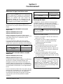
Determine Type of Solution Needed . . . . . . . . . . . . . . . . . . . . . . . . . . . . . . . . . . . . 10
Manitowoc Ice Machine Cleaner . . . . . . . . . . . . . . . . . . . . . . . . . . . . . . . . . . . . 10
Manitowoc Ice Machine Sanitizer . . . . . . . . . . . . . . . . . . . . . . . . . . . . . . . . . . . 10
Hose Priming . . . . . . . . . . . . . . . . . . . . . . . . . . . . . . . . . . . . . . . . . . . . . . . . . . . . . . 10
Setting Frequency of Cleanings . . . . . . . . . . . . . . . . . . . . . . . . . . . . . . . . . . . . . . . 11
Installing/Replacing Cleaner or Sanitizer Bottles . . . . . . . . . . . . . . . . . . . . . . . . . 11
AuCS®-SI . . . . . . . . . . . . . . . . . . . . . . . . . . . . . . . . . . . . . . . . . . . . . . . . . . . . . 11
AuCS®-SO . . . . . . . . . . . . . . . . . . . . . . . . . . . . . . . . . . . . . . . . . . . . . . . . . . . . 11
Changing the Solution Type . . . . . . . . . . . . . . . . . . . . . . . . . . . . . . . . . . . . . . . . . . 12
Automatic Operation . . . . . . . . . . . . . . . . . . . . . . . . . . . . . . . . . . . . . . . . . . . . . . . . 13
Manual Start Operation . . . . . . . . . . . . . . . . . . . . . . . . . . . . . . . . . . . . . . . . . . . . . . 13
Changing Switch Position During Automatic Operation . . . . . . . . . . . . . . . . . . . 14
Removal from Service/Winterization . . . . . . . . . . . . . . . . . . . . . . . . . . . . . . . . . . . 14
Section 4
Customer Support
Commercial Ice Machine Warranty . . . . . . . . . . . . . . . . . . . . . . . . . . . . . . . . . . . . . 15
Residential Ice Machine Limited Warranty . . . . . . . . . . . . . . . . . . . . . . . . . . . . . . . 16

Part Number 000007647 06/11 3
Section 1
General Information
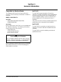
Compatible Ice Machine Models
The S-Model AuCS® (AuCS®-SI and AuCS®-SO)
accessory can be used only on Manitowoc S-Model ice
machines.
MODEL COMPATIBILITY:
AuCS®-SI
• S450/S500/S600/S850/S1000/S1200/
S1400/S1600/S1800
AuCS®-SO
Due to cabinet size the AuCS®-SI is not compatible with
all S Model Ice Machines. The following ice machines
must use the AuCS®-SO accessory
• S300/S320/S420/
S1470C/S1870C/S2070C/
IB600C/IB800C/IB1000C
NOTE: Automatic Cleaning Systems are not compatible
with S Model 3000 Series, S Model Flake/Nugget or
SM50 model ice machines.
AuCS®-SI
The AuCS®-SI mounts internally in S Model ice
machines. S Model Ice Machines can be ordered direct
from the factory with the AuCS®-SI installed (refer to
chart for available models). If your ice machine has a
factory installed AuCS®-SI, proceed to Section 3
Operation.
If the AuCS®-SI was not factory installed a trained and
qualified technician must perform the installation.
AuCS®-SO
The AuCS®-SO is mounted on the wall near the ice
machine, or on the bin with the included bracket and
hardware.
The AuCS®-SO must be installed by a trained and
qualified technician.
!
Warning
PERSONAL INJURY POTENTIAL
Do not operate equipment that has been misused,
abused, neglected, damaged, or altered/modified
from that of original manufactured specifications.

4 Part Number 000007647 06/11
Section 2
Installation Instructions
General
These instructions are provided to assist the qualified
installer. Check your local Yellow Pages for the name of
the nearest Manitowoc distributor, or call Manitowoc
Foodservice for information regarding start-up services.
Please contact you local Manitowoc Distributor or call
Manitowoc Foodservice for assistance if you encounter
a problem that is not covered by this manual.
Electrical Service
GENERAL
AuCS®-SI
Line voltage is obtained from the ice machine. Refer to
the Model/Serial plate on the ice machine and
AuCS®-SI to verify both voltages are the same.
AuCS®-SO
Line voltage is obtained from the ice machine or an
electrical outlet. Verify the ice machine voltage matches
the AuCS®-SO or a receptacle with the correct voltage
is available at the AuCS®-SO mounting location.
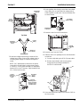
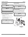
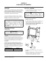
AuCS®-SI Installation
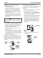
1. Disconnect power to ice machine at the electrical
disconnect.
2. Remove right front door.
3. Remove the water trough.
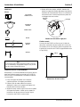
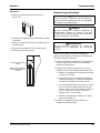
4. Locate the water inlet tube on the right hand side
(see below) of the ice machine base. Directly to the
left of the tube there is a small plug that must be
removed. Press up on the plug until it is out.
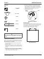
5. Locate the plug and remove it from the ice machine.
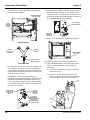
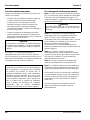
6. Install Y connector through the hole in the ice
machine base. Connect the clear vinyl tubing to one
side of the Y branch, the other side is for the plug
removed in step 5.
Important
Failure to follow these installation guidelines may
affect warranty coverage. Improper installation will
affect dispensing rate. Install only within the
parameters outlined in this installation manual.
!
Warning
A trained and qualified technician must install the
AuCS®-SI or AuCS®-SO.
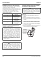
Voltage Phase Cycle Amperage
115/1/60 0.3
208-230/1/50/60 0.1
!
Warning
Disconnect power to ice machine at the electrical
disconnect. Moving the ice machine toggle switch to
the off position does not disconnect line voltage.
Water Inlet
Tubing
Plug Location
Press up on
bottom of plug
to pop out

Section 2 Installation Instructions
Part Number 000007647 06/11 5
Top View
Y-Connector
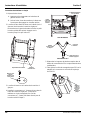
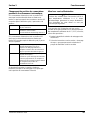
7. Route line voltage wires through control box line
voltage heyco fitting. Connect line voltage wires to
incoming power supply of contactor and ground
screw.
NOTE: On S QuietQube Ice Machines the power
connection is made at the incoming power supply
(L1 and L2). Cut-off yellow terminal (L2) and purple
terminal (L1) on AuCS harness. Strip insulation back
1/2" (13 mm) and connect.
8. Route modular wire through control box low voltage
heyco fitting. Do not route with line voltage wiring,
erratic operation could result. Connect modular wire
to control board.
9. Remove screw from ice machine base.
10. Remove cover from AuCS®-SI.
11. Slide the AuCS®-SI partially into ice machine below
control box.
A. Connect vinyl tubing to AuCS®-SI pump outlet.
B. Route communication wire (4 prong plug)
through left heyco fitting and attach to
AuCS®-SI control board.
12. Use screw removed in step 6 to secure AuCS®-SI to
the ice machine.
Route tubing
to this area
Insert Y
connector
with tubing
Connect
tubing
Install plug
removed in
Step 5
Into Base of
Ice Machine
Line Voltage
Heyco
Fittings
Connect to
incoming power
supply of contactor
observing proper
polarity for 115V
Connect
ground wire
to ground
screw
Low Voltage
Heyco Fitting
Control Board
Connection
SCREW
LOCATION
12
11B
11A

Installation Instructions Section 2
6
Part Number 000007647 06/11
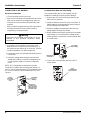
AuCS®-SO Installation
LOCATION / MOUNTING
The location selected for the AuCS®-SO accessory
must meet the following criteria. If any of these criteria
are not met, select another location.
• The location must be free of airborne and other
contaminants.
• The air temperature must be at least 40°F (4°C), but
must not exceed 110°F (43°C).
• The location must not be near heat-generating
equipment or in direct sunlight.
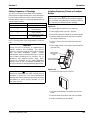
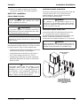
HEIGHT REQUIREMENT
Either the base or the top of the AuCS®-SO accessory
must be within 2" (5 cm) of the base of the ice machine.
Do not mount the AuCS®-SO too high or too low.
DISTANCE REQUIREMENT
The AuCS®-SO must be mounted within 9 feet (2.7 m)
of the ice machine to accommodate the low voltage
communication wire and tubing. The tubing may be
shortened to accommodate a run of less than 9 feet
(2.7 m).
!
Warning
All wiring must conform to local, state and national
codes.
!
Warning
The ice machine and AuCS®-SO must be grounded
in accordance with national and local electrical
codes.
Important
Observe correct polarity of incoming line voltage.
!
Caution
The AuCS® accessory must be protected if it will be
subjected to temperatures below 32°F (0°C).
Failure caused by exposure to freezing
temperatures is not covered by the warranty. See
“Removal from Service/Winterization”.
!
Caution
The cleaner or sanitizer may siphon (or dispense
improperly) into the ice machine water trough if the
AuCS®-SO is mounted too high or too low.
!
Caution
Do not extend the length of the 9-foot (2.7 m) low
voltage communication wire or tubing. The correct
amount of solution will not dispense.
BASE OF ICE
MACHINE
2"
(5 cm)
BOX BASE OR BOX TOP
MUST BE WITHIN 2"
(5 cm) OF ICE MACHINE
BASE

Section 2 Installation Instructions
Part Number 000007647 06/11 7
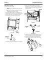
MOUNTING
Parts
Mounting to Bin or Dispenser
NOTE: The ice machine’s serviceability may be reduced
when the AuCS®-SO is mounted to the bin or dispenser.
Wall mounting is recommended.
1. Set the mounting bracket over the bin top rail at
desired location.
2. Remove the backing from the foam adhesive tape.
Apply tape to mounting bracket, and along the entire
bin rail.
3. Align the AuCS®-SO key slots with the mounting
bracket tabs. Verify the tabs are at the top of the key
slots and that the AuCS®-SO is level.
4. Remove the backing from the adhesive bumpers.
Attach bumpers to the mounting bracket directly
above the AuCS®-SO control box. This eliminates
upward movement and stops the tabs from
disengaging the key slots.
Mounting to Ice Machine
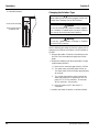
Mounting to Wall
The AuCS®-SO is mounted to the wall using the two key
slots in the back wall of the accessory. Screw fasteners
(not supplied) must hold the entire weight of the
AuCS®-SO (approximately 10 lbs. [4.5 kg]).
Key Slot Dimensions
!
Caution
The AuCS®-SO may be mounted to the bin or
dispenser only when permitted by local electrical
codes.
1/2" PVC CONDUIT
FITTING
HOSE CLAMPS
LOCKNUT
BUMPER
FOAM TAPE
BRACKET
AuCS
AuCS
T
M
T
M
Mounting
Bracket
Gasket
Bumper
6.56 in.
(16.6 cm)

Installation Instructions Section 2
8
Part Number 000007647 06/11
CONNECTION TO ICE MACHINE
Electrical Connections
1. Check electrical code for your area.
• When local code allows, the included wire and strain
relief can be used for line voltage wiring. Remove
knockout from ice machine and install strain relief
and wire.
• When conduit is required remove strain relief and ice
machine electrical knockout. Install conduit as
required by your electrical code.
• Connections on ice machines vary. Refer to the
diagram for the ice machine you are working on. If
the model you are working on is not shown, refer the
model’s Installation, Use and Care Manual.
2. Remove the front, top, and right side panels from the
ice machine.
3. Route line voltage wires through control box line
voltage heyco fitting. Connect line voltage wires to
incoming power supply of contactor and ground
screw.
NOTE: On S QuietQube Ice Machines the power
connection is made at the incoming power supply (L1
and L2). Cut-off yellow terminal (L2) and purple terminal
(L1) on AuCS harness. Strip insulation back 1/2" and
connect.
Communication Wire and Vinyl Tubing
The communication wire and vinyl tubing must be
installed in conduit to protect them from damage.
1. Remove the 7/8" access hole plug located on the
back of the ice machine.
2. Install conduit from the AuCS to the ice machine. A
pulling elbow is recommended for easier routing of
the vinyl tubing and modular wire.
3. Route low voltage communication wire and vinyl
tubing together through the conduit.
4. Route modular wire through control box low voltage
heyco fitting. Do not route with line voltage wiring,
erratic operation could result. Connect modular wire
to control board.
5. Connect the communication wire to the AuCS
control board.
!
Warning
Disconnect the electrical power supply to the ice
machine at the electrical disconnect before
proceeding.
Line Voltage
Heyco
Fittings
Connect to
incoming power
supply of contactor
observing proper
polarity for 115V
Connect
ground wire
to ground
screw
Low Voltage
Heyco Fitting
Control Board
Connection
AuCS
Communication
Plug Connection

Section 2 Installation Instructions
Part Number 000007647 06/11 9
Vinyl Tubing Connection
1. Remove the water trough.
A. Depress tabs on right and left side of the water
trough.
B. Allow front of water trough to drop as you pull
forward to disengage the rear pins.
2. Locate the water inlet tube on the right hand side
(see below) of the ice machine base. Directly to the
left of the tube there is a small plug that must be
removed. Press up on the plug until it is out.
3. Locate the plug and remove it from the ice machine.
4. Install Y connector through the hole in the ice
machine base. Connect the clear vinyl tubing to one
side of the Y branch, the other side is for the plug
removed in step 3.
Top View
Y-Connector
5. Determine the amount of tubing required in the
AuCS control box and cut off the excess tubing.
6. Slide the 3/8" hose clamp onto the tubing and
connect it to the fitting on the AuCS®-SO pump.
Water Inlet
Tubing
Plug Location
Press up on
bottom of plug
to pop out
Route tubing
to this area
Insert Y
connector
with tubing
Connect
tubing
Install plug
removed in
Step 3
Into Base of
Ice Machine
Use hose
clamp to
secure tubing
to pump

10 Part Number 000007647 06/11
Section 3
Operation
Determine Type of Solution Needed
The AuCS® accessory will dispense Cleaner OR
Sanitizer. It cannot dispense both at the same time.
MANITOWOC ICE MACHINE CLEANER
Part Number 94-0546-3 (AuCS®-SO)
Part Number 40-1326-3 (AuCS®-SI)
Ice Machine Cleaner is used to control build-up and to
remove lime scale or other mineral deposits. It will not
“sanitize” the ice machine.
It is recommended for use in places that have lime scale
or other mineral deposits, but no problems with slime.
MANITOWOC ICE MACHINE SANITIZER
Part Number 94-0565-3 (AuCS®-SO)
Part Number 40-1327-3 (AuCS®-SI)
Ice Machine Sanitizer is used for sanitizing and
controlling algae build-up (slime) and other bacterial
growth. The ice machine (and bin or dispenser) must be
sanitized on a regular schedule, following Manitowoc
recommendations and local regulations.
It is recommended for use in places such as pizzerias,
bars, bakeries, etc., that have airborne bacteria (yeast).
Sanitizing is also recommended in places that do not
have lime scale (or other mineral deposit problems).
Hose Priming
The dispenser pump requires priming after initial
installation, or if the hose between the AuCS®-SI
reservoir and pump has been pumped dry or the tubing
between the AuCS®-SO pump and the ice machine has
been pumped dry.
Perform the following procedure:
1. Move the ice machine toggle switch to CLEAN.
2. The water pump and dump valve will turn on. The
dump valve will shut off after approximately
45 seconds.
3. The control waits until water contacts the water level
probe then energizes the AuCS® pump (22" or 30"
ice machines - 30 seconds, 48" ice machines -
60 seconds).
4. Allow the ice machine to complete the cleaning or
sanitizing cycle. Refer to “Manual Start Operation”
for details.
!
Caution
Use only Manitowoc approved Ice Machine
Cleaner & Sanitizer. It is a violation of Federal law
to use these solutions in a manner inconsistent
with their labeling. Read and understand all labels
on the bottles before use.
Model Amount of Cleaner Dispensed
22" or 30"
Ice Machine
3 oz (88 ml)
48" Ice Machine 6 oz (177 ml)
Model Amount of Sanitizer Dispensed
22" or 30"
Ice Machine
3 oz (88 ml)
48" Ice Machine 6 oz (176 ml)
!
Warning
Do not blow into or suck on the hose in an attempt
to prime it.
Important
The priming procedure starts the automatic cleaning
mode. Upon moving the ice machine toggle switch
to ICE, the ice machine will run through 6 rinse and
dump cycles before making ice.

Section 3 Operation
Part Number 000007647 06/11 11
Setting Frequency of Cleanings
The AuCS® is factory-set to initiate and complete a
clean sequence approximately once every two weeks.
For less frequent cleaning, set the selector switch as
indicated below. Refer to “Component Identification” for
selector switch location.
NOTE: Switch position 4-9 are inoperative. Do not use
them.
Installing/Replacing Cleaner or Sanitizer
Bottles
AUCS®-SI
1. Remove right front door from ice machine.
2. Place toggle switch in the OFF position.
3. Disconnect tubing from bottle, then remove bottle.
4. Remove bottle cap and foil seal from new bottle,
then replace bottle cap.
5. Cut 1/4" (6 mm) off end of bottle and reconnect
tubing.
6. Place toggle switch in ice position and reinstall ice
machine door.
AUCS®-SO
1. Remove left panel from AuCS®-SO.
2. Unscrew nozzle/tubing from bottle, then remove
bottle.
3. Remove bottle cap and foil seal from new bottle.
4. Install nozzle/tubing on new bottle.
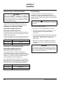
Switch Position Time Between Cleanings
0 No cleaning (OFF)
1
Approximately 2 weeks
(1120 harvests)
2
Approximately 4 weeks
(2240 harvests)
3
Approximately 12 weeks
(6720 harvests)
Important
Using the AuCS® accessory is supplemental to
regular cleaning and sanitizing. The AuCS®
accessory will clean surfaces that come in contact
with the water distribution system. Periodic
maintenance must be performed every six months
that includes sanitizing the ice machine, bin (or
dispenser) and adjacent surface areas, which
cannot be contacted by the water distribution
system. Refer to the ice machine installation use
and care manual for cleaning/sanitizing procedures.
!
Warning
Read and understand this entire manual prior to
operation of the AuCS®. You must understand all
warning and caution statements and follow all safety
precautions to assure proper operation of your
AuCS® accessory.
!
Caution
Do not mix Cleaner and Sanitizer solutions together.
It is a violation of Federal law to use these solutions
in a manner inconsistent with their labeling.
Remove Cap and Foil
Seal, Then Replace Cap
Trim End of Bottle,
Then Connect To
Tubing

Operation Section 3
12
Part Number 000007647 06/11
5. Reinstall left panel.
Changing the Solution Type
Use the following procedure to flush the system prior to
changing from Cleaner to Sanitizer or from Sanitizer to
Cleaner.
1. Remove the bottle of Cleaner or Sanitizer from the
AuCS®. Flush the bottle thoroughly then fill with
water.
2. Repeat the following until the water bottle is empty
(approximately 8 times):
A. Move the ice machine toggle switch to CLEAN.
B. The water pump and dump valve will turn on.
The dump valve will shut off after approximately
45 seconds.
C. The control waits until the water contacts the
water level probe then energizes the AuCS®
pump (22" or 30" ice machines - 30 seconds,
48" ice machines - 60 seconds).
D. Move the switch to OFF after step C is
completed.
3. Install a new bottle of cleaner or sanitizer solution.
Unscrew cap and remove bottle
Remove cap and foil seal from
new bottle and install
!
Caution
Wear rubber gloves and safety goggles (and/or face
shield) when handling Cleaner and Sanitizer.
!
Caution
Do not mix Cleaner and Sanitizer solutions together.
It is a violation of Federal law to use these solutions
in a manner inconsistent with their labeling.
!
Warning
Do not use 1 gallon bottles of Cleaner or Sanitizer
on the AuCS® accessory.

Section 3 Operation
Part Number 000007647 06/11 13
Automatic Operation
The following occurs when the toggle switch is in the ICE
position:
• The ice machine control board counts the number of
harvest cycles.
• The AuCS® accessory interrupts the ice making
mode and starts the clean sequence when the
harvest count equals the “Frequency of Cleaning”
setting of the AuCS®.
• When the clean sequence is complete
(approximately 30 minutes), ice making resumes
automatically, and the “Harvest Count” is reset to
zero.
NOTE: The harvest count is automatically reset after the
AuCS® sequence is completed. It cannot be reset by
unplugging the modular wire, changing the switch
position, power loss, etc.
Manual Start Operation
Step 1 Set the toggle switch to the OFF position after
ice falls from the evaporator at the end of a Harvest
cycle. Or, set the switch to the OFF position and allow
the ice to melt off the evaporator.
Step 2 To start the automatic cleaning system, move
the toggle switch to the CLEAN position. The water will
flow through the water dump valve and down the drain.
The clean light will turn on to indicate the ice machine is
in Clean Mode.
The AuCS® pump energizes automatically to add
cleaner or sanitizer to the ice machine.
Step 3 The ice machine will automatically time out a
ten minute wash cycle, followed by six rinse cycles, de-
energize the clean light and stop. This entire cycle lasts
approximately 30 minutes.
Step 4 After the clean sequence is finished, move the
toggle switch to the ICE position.
Step 5 The ice machine may be set to start and finish a
clean sequence, then automatically start ice making
again.
You must wait about one minute into the cleaning cycle
(until water starts to flow over the evaporator), then
move the toggle switch from CLEAN to ICE position.
When the clean sequence is complete, the ice making
sequence will start automatically.
Important
Opening the curtain switch will interrupt the clean
sequence. The sequence will resume from the point
of interruption when the curtain re-closes.
Important
Using the AuCS® accessory is supplemental to
regular cleaning and sanitizing. The AuCS®
accessory will clean surfaces that come in contact
with the water distribution system. Periodic
maintenance must be performed every six months
that includes sanitizing the bin (or dispenser) and
adjacent surface areas, which cannot be contacted
by the water distribution system. Refer to the ice
machine installation use and care manual for
cleaning/sanitizing procedures.
!
Caution
Never use anything to force ice from the evaporator.
Damage may result.

Operation Section 3
14
Part Number 000007647 06/11
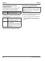
Changing Switch Position During
Automatic Operation
If the toggle switch is moved to OFF before the water
inlet valve energizes or the water pump starts (45
seconds into the cycle) and is then switched to:
If the toggle switch is moved to OFF after the water inlet
valve energizes (more than 45 seconds into the cycle)
and is then switched to:
After 45 seconds, the ice machine will complete the
clean sequence regardless of toggle switch position.
Removal from Service/Winterization
If the AuCS® is to be removed from service for extended
periods, or if it is to be exposed to ambient temperatures
32°F (0°C) or below, follow this procedure:
1. Remove the Cleaning or Sanitizing solution bottle.
2. Follow the instructions under “Hose Priming” to
pump all of the solution out of the dispensing pump
and line.
ICE A normal ice making sequence begins.
CLEAN A manual clean sequence begins.
(See “Manual Start Operation”)
ICE The clean sequence resumes from the
point of interruption. After completion of the
cleaning sequence, the counter resets and
the ice machine starts making ice.
CLEAN The clean sequence resumes from the
point of interruption.
After completion of the 10-minute wash and
6 rinse cycles, the counter resets and the
ice machine awaits a change in the toggle
switch position.
!
Caution
Leaving solutions in the AuCS® in freezing
temperatures may result in severe damage to the
dispensing pump. A failure of this nature is not
covered by the warranty.

Part Number 000007647 06/11 15
Section 4
Customer Support
Commercial Ice Machine Warranty
Manitowoc Ice, Inc. (hereinafter referred to as the “COMPANY”) warrants for a period of thirty-six months from the
installation date (except as limited below) that new accessory manufactured by the COMPANY shall be free of defects
in material or workmanship under normal and proper use and maintenance as specified by the COMPANY and upon
proper installation and start-up in accordance with the instruction manual supplied with the accessory.
The obligation of the COMPANY under this warranty is limited to the repair or replacement of parts, components, or
assemblies that in the opinion of the COMPANY are defective. This warranty is further limited to the cost of parts,
components or assemblies and standard straight time labor charges at the servicing location.
Time and hourly rate schedules, as published from time to time by the COMPANY, apply to all service procedures.
Additional expenses including without limitation, travel time, overtime premium, material cost, accessing or removal of
the accessory, or shipping are the responsibility of the owner, along with all maintenance, adjustments, and cleaning
costs. Labor covered under this warranty must be performed by a COMPANY Contracted Service Representative or a
refrigeration service agency as qualified and authorized by the COMPANY’s local Distributor. The COMPANY’s
liability under this warranty shall in no event be greater than the actual purchase price paid by the customer for the
accessory.
The foregoing warranty shall not apply to (1) any part or assembly that has been altered, modified, or changed; (2)
any part or assembly that has been subjected to misuse, abuse, neglect, or accidents; (3) ice machine cleaner or
sanitizer solution; (4) any accessorythat has been installed and/or maintained inconsistent with the technical
instructions provided by the COMPANY; or (5) any accessoryinitially installed more than five years from the serial
number production date.
The accessory is designed to operate only on the COMPANY’s ice machines.
THIS WARRANTY IS IN LIEU OF ALL OTHER WARRANTIES OR GUARANTEES OF ANY KIND, EXPRESSED
OR IMPLIED, INCLUDING ANY IMPLIED WARRANTY OF MERCHANTABILITY OR FITNESS FOR A
PARTICULAR PURPOSE. In no event shall the COMPANY be liable for any special, indirect, incidental or
consequential damages. Upon the expiration of the warranty period, the COMPANY’s liability under this warranty shall
terminate. The foregoing warranty shall constitute the sole liability of the COMPANY and the exclusive remedy of the
customer or user.
To secure prompt and continuing warranty service, the warranty registration card must be completed and sent to the
COMPANY within five (5) days from the installation date.
Complete the following and retain for your record:
Distributor/Dealer ______________________________________________________________________________
Model Number ________________________________ Serial Number __________________________________
Installation Date _______________________________________________________________________________
MANITOWOC ICE, INC.
2110 So. 26th St., P.O. Box 1720, Manitowoc, WI 54221-1720
Telephone: 920-682-0161 Fax: 920-683-7585
Web Site - www.manitowocice.com
Form 80-0375-3 Rev. 01-02

Customer Support Section 4
16
Part Number 000007647 06/11
Residential Ice Machine Limited Warranty
WHAT DOES THIS LIMITED WARRANTY COVER?
Subject to the exclusions and limitations below, Manitowoc
Foodservice (“Manitowoc”) warrants to the original consumer
that any new ice machine manufactured by Manitowoc (the
“Product”) shall be free of defects in material or workmanship
for the warranty period outlined below under normal use and
maintenance, and upon proper installation and start-up in
accordance with the instruction manual supplied with the
Product.
HOW LONG DOES THIS LIMITED WARRANTY LAST?
Product Covered
Warranty Period
Ice Machine Twelve (12) months
from the sale date
WHO IS COVERED BY THIS LIMITED WARRANTY?
This limited warranty only applies to the original consumer of
the Product and is not transferable.
WHAT ARE MANITOWOC ICE’S OBLIGATIONS UNDER
THIS LIMITED WARRANTY?
If a defect arises and Manitowoc receives a valid warranty
claim prior to the expiration of the warranty period, Manitowoc
shall, at its option: (1) repair the Product at Manitowoc’s cost,
including standard straight time labor charges, (2) replace the
Product with one that is new or at least as functionally
equivalent as the original, or (3) refund the purchase price for
the Product. Replacement parts are warranted for 90 days or
the balance of the original warranty period, whichever is
longer. The foregoing constitutes Manitowoc’s sole obligation
and the consumer’s exclusive remedy for any breach of this
limited warranty. Manitowoc’s liability under this limited
warranty is limited to the purchase price of Product. Additional
expenses including, without limitation, service travel time,
overtime or premium labor charges, accessing or removing
the Product, or shipping are the responsibility of the
consumer.
HOW TO OBTAIN WARRANTY SERVICE
To obtain warranty service or information regarding your
Product, please contact us at:
MANITOWOC FOODSERVICE
2110 So. 26th St.
P.O. Box 1720,
Manitowoc, WI 54221-1720
Telephone: 920-682-0161 Fax: 920-683-7585
www.manitowocice.com
WHAT IS NOT COVERED?
This limited warranty does not cover, and you are solely
responsible for the costs of: (1) periodic or routine
maintenance, (2) repair or replacement of the Product or parts
due to normal wear and tear, (3) defects or damage to the
Product or parts resulting from misuse, abuse, neglect, or
accidents, (4) defects or damage to the Product or parts
resulting from improper or unauthorized alterations,
modifications, or changes; and (5) defects or damage to any
Product that has not been installed and/or maintained in
accordance with the instruction manual or technical
instructions provided by Manitowoc. To the extent that
warranty exclusions are not permitted under some state laws,
these exclusions may not apply to you.
E
XCEPT AS STATED IN THE FOLLOWING SENTENCE, THIS LIMITED
WARRANTY IS THE SOLE AND EXCLUSIVE WARRANTY OF
MANITOWOC WITH REGARD TO THE PRODUCT. ALL IMPLIED
W
ARRANTIES ARE STRICTLY LIMITED TO THE DURATION OF THE
LIMITED WARRANTY APPLICABLE TO THE PRODUCTS AS STATED
ABOVE, INCLUDING BUT NOT LIMITED TO, ANY WARRANTY OF
M
ERCHANTABILITY OR OF FITNESS FOR A PARTICULAR
PURPOSE.
Some states do not allow limitations on how long an implied
warranty lasts, so the above limitation may not apply to you.
I
N NO EVENT SHALL MANITOWOC OR ANY OF ITS AFFILIATES BE
L
IABLE TO THE CONSUMER OR ANY OTHER PERSON FOR ANY
INCIDENTAL, CONSEQUENTIAL OR SPECIAL DAMAGES OF ANY
KIND (INCLUDING, WITHOUT LIMITATION, LOSS PROFITS,
R
EVENUE OR BUSINESS) ARISING FROM OR IN ANY MANNER
CONNECTED WITH THE PRODUCT, ANY BREACH OF THIS LIMITED
WARRANTY, OR ANY OTHER CAUSE WHATSOEVER, WHETHER
B
ASED ON CONTRACT, TORT OR ANY OTHER THEORY OF
LIABILITY.
Some states do not allow the exclusion or limitation of
incidental or consequential damages, so the above limitation
or exclusion may not apply to you.
HOW STATE LAW APPLIES
This limited warranty gives you specific legal rights, and you
may also have rights that vary from state to state or from one
jurisdiction to another.
REGISTRATION CARD
To secure prompt and continuing warranty service, this
warranty registration card must be completed and sent to
Manitowoc within thirty (30) days from the sale date. Complete
the following registration card and send it to Manitowoc.

Part Number 000007647 06/11 17
Table des matières
Section 1
Généralités
Modèles de machines à glaçons compatibles . . . . . . . . . . . . . . . . . . . . . . . . . . . 18
Compatibilité des modèles : . . . . . . . . . . . . . . . . . . . . . . . . . . . . . . . . . . . . . . . 18
AuCS®-SI . . . . . . . . . . . . . . . . . . . . . . . . . . . . . . . . . . . . . . . . . . . . . . . . . . . . . . . . . 18
AuCS®-SO . . . . . . . . . . . . . . . . . . . . . . . . . . . . . . . . . . . . . . . . . . . . . . . . . . . . . . . . 18
Section 2
Instructions d’installation
Généralités . . . . . . . . . . . . . . . . . . . . . . . . . . . . . . . . . . . . . . . . . . . . . . . . . . . . . . . . 19
Alimentation électrique . . . . . . . . . . . . . . . . . . . . . . . . . . . . . . . . . . . . . . . . . . . . . . 19
Généralités . . . . . . . . . . . . . . . . . . . . . . . . . . . . . . . . . . . . . . . . . . . . . . . . . . . . 19
AuCS®-SI - Installation . . . . . . . . . . . . . . . . . . . . . . . . . . . . . . . . . . . . . . . . . . . . . . 19
AuCS®-SO - Installation . . . . . . . . . . . . . . . . . . . . . . . . . . . . . . . . . . . . . . . . . . . . . 21
Emplacement/Fixation . . . . . . . . . . . . . . . . . . . . . . . . . . . . . . . . . . . . . . . . . . . 21
Condition requise de hauteur . . . . . . . . . . . . . . . . . . . . . . . . . . . . . . . . . . . . . . 21
Condition requise de distance . . . . . . . . . . . . . . . . . . . . . . . . . . . . . . . . . . . . . . 21
Montage . . . . . . . . . . . . . . . . . . . . . . . . . . . . . . . . . . . . . . . . . . . . . . . . . . . . . . 22
Connexion à la machine à glaçons . . . . . . . . . . . . . . . . . . . . . . . . . . . . . . . . . . 23
Section 3
Fonctionnement
Déterminer le type de solution requis . . . . . . . . . . . . . . . . . . . . . . . . . . . . . . . . . . 25
Nettoyant pour machines à glaçons Manitowoc . . . . . . . . . . . . . . . . . . . . . . . . 25
Désinfectant pour machines à glaçons Manitowoc . . . . . . . . . . . . . . . . . . . . . . 25
Amorçage du tuyau . . . . . . . . . . . . . . . . . . . . . . . . . . . . . . . . . . . . . . . . . . . . . . . . . 25
Réglage de la fréquence des nettoyages . . . . . . . . . . . . . . . . . . . . . . . . . . . . . . . 26
Installation/Remplacement des bouteilles de nettoyant ou de désinfectant . . . 26
AuCS®-SI . . . . . . . . . . . . . . . . . . . . . . . . . . . . . . . . . . . . . . . . . . . . . . . . . . . . . 26
AuCS®-SO . . . . . . . . . . . . . . . . . . . . . . . . . . . . . . . . . . . . . . . . . . . . . . . . . . . . 27
Changer le type de solution . . . . . . . . . . . . . . . . . . . . . . . . . . . . . . . . . . . . . . . . . . 27
Fonctionnement automatique . . . . . . . . . . . . . . . . . . . . . . . . . . . . . . . . . . . . . . . . . 28
Fonctionnement de démarrage manuel . . . . . . . . . . . . . . . . . . . . . . . . . . . . . . . . . 28
Changement de position du commutateur pendant le fonctionnement
automatique . . . . . . . . . . . . . . . . . . . . . . . . . . . . . . . . . . . . . . . . . . . . . . . . . . . . . . . 29
Mise hors service/Hivérisation . . . . . . . . . . . . . . . . . . . . . . . . . . . . . . . . . . . . . . . . 29
Section 4
Service clientèle
Garantie commerciale de la machine à glaçons . . . . . . . . . . . . . . . . . . . . . . . . . . 30
Garantie limitée résidentielle de la machine à glaçons . . . . . . . . . . . . . . . . . . . . 31

18 Part Number 000007647 06/11
Section 1
Généralités
Modèles de machines à glaçons
compatibles
L’accessoire Modèle S AuCS® (AuCS®-SI et
AuCS®-SO) ne peut être utilisé que sur les machines à
glaçons Modèle S Manitowoc.
COMPATIBILITÉ DES MODÈLES :
AuCS®-SI
• S450/S500/S600/S850/S1000/S1200/S1400/S1600/
S1800
AuCS®-SO
En raison de la taille de l’armoire, le AuCS®-SI n’est pas
compatible avec toutes les machines à glaçons Modèle
S. Les machines à glaçons suivantes doivent utiliser
l’accessoire AuCS®-SO
• S300/S320/S420/S1470C/S1870C/S2070C/IB600C/
IB800C/IB1000C
REMARQUE : Les systèmes de nettoyage automatique
ne sont pas compatibles avec les machines à glaçons
Modèle S Série 3000, Modèle S Flake/Nugget ou
Modèle SM50.
AuCS®-SI
L’accessoire AuCS®-SI se monte à l’intérieur des
machines à glaçons Modèle S. Les machines à glaçons
Modèle S peuvent être commandées directement
auprès de l’usine avec l’accessoire AuCS®-SI installé
(consulter le tableau pour les modèles disponibles). Si la
machine à glaçons a un AuCS®-SI installé en usine,
passer à la Section 3 Fonctionnement.
Si l’accessoire AuCS®-SI n’a pas été installé en usine,
un technicien expérimenté et qualifié doit procéder à
l’installation.
AuCS®-SO
L’accessoire AuCS®-SO est monté sur le mur à
proximité de la machine à glaçons ou sur le bac à l’aide
du support et de la visserie fournis.
L’accessoire AuCS®-SO doit être installé par un
technicien expérimenté et qualifié.
!
Avertissement
RISQUE DE BLESSURES CORPORELLES
Ne pas utiliser un équipement qui aura été mal
utilisé, abusé, négligé, endommagé ou dont les
spécifications originales de fabrication auront été
altérées/modifiées.

Part Number 000007647 06/11 19
Section 2
Instructions d’installation
Généralités
Ces instructions sont fournies pour assister l’installateur
qualifié. Consulter les Pages jaunes locales pour trouver
le nom du distributeur Manitowoc le plus proche ou
appeler Manitowoc Foodservice pour toute information
concernant les services de mise en route.
Contacter le distributeur Manitowoc local ou appeler
Manitowoc Foodservice pour toute assistance lors d’un
problème non traité dans le présent manuel.
Alimentation électrique
GÉNÉRALITÉS
AuCS®-SI
La tension de secteur est obtenue de la machine à
glaçons. Consulter la plaque de référence/le numéro de
série sur la machine à glaçons et l’accessoire AuCS®-SI
pour vérifier que les deux tensions sont les mêmes.
AuCS®-SO
La tension de secteur est obtenue de la machine à
glaçons ou d’une prise électrique. Vérifier que la tension
de la machine à glaçons correspond à l’accessoire
AuCS®-SO ou qu’une prise ayant la tension correcte est
disponible à l’emplacement de fixation de l’accessoire
AuCS®-SO.
AuCS®-SI - Installation
1. Couper l’alimentation à la machine à glaçons au
niveau du sectionneur électrique.
2. Déposer la porte avant droite.
3. Déposer le bac à eau.
4. Localiser le tube d’arrivée d’eau sur la droite (voir ci-
dessous) de la base de la machine à glaçons.
Directement sur la gauche du tube se trouve un petit
bouchon qui doit être enlevé. Appuyer sur le
bouchon jusqu’à ce qu’il soit sorti.
5. Localiser le bouchon et le retirer de la machine à
glaçons.
6. Installer le connecteur en Y à travers le trou dans la
base de la machine à glaçons. Connecter la
tubulure en vinyle transparent d’un côté du
Important
Le non-respect de ces directives d’installation
risque d’affecter la couverture de garantie. Une
mauvaise installation affectera le débit de
distribution. Installer uniquement dans les limites
des paramètres décrits dans ce manuel
d’installation.
! Avertissement
Un technicien expérimenté et qualifié doit installer
l’accessoire AuCS®-SI ou AuCS®-SO.
Tension/Phase/Cycle Intensité
115/1/60 0,3
208-230/1/50/60 0,1
! Avertissement
Couper l’alimentation à la machine à glaçons au
niveau du sectionneur électrique. Mettre le
commutateur à bascule de la machine à glaçons en
position OFF ne déconnecte pas la tension de secteur.
Tubulure
d’arrivée d’eau
Emplacement
du bouchon
Appuyer sur le
fond du
bouchon pour
le faire sortir

Instructions d’installation Section 2
20
Part Number 000007647 06/11
connecteur en Y, l’autre côté étant réservé pour le
bouchon retiré à l’étape 5.
Vue du dessus
Connecteur en Y
7. Acheminer les fils de tension de secteur à travers le
raccord Heyco de tension de secteur de boîtier de
commande. Connecter les fils de tension de secteur
à l’alimentation électrique entrante du contacteur et
de la vis de borne de terre.
REMARQUE : Sur les machines à glaçons S
QuietQube, le raccord d’alimentation est effectué au
niveau de l’alimentation électrique entrante (L1 et
L2). Couper la borne jaune (L2) et la borne violette
(L1) sur le faisceau AuCS. Dénuder l’isolation sur 13
mm (1/2") et connecter.
8. Acheminer le fil modulaire à travers le raccord Heyco
de basse tension du boîtier de commande. Ne pas
acheminer avec le câble de tension de secteur et ce,
pour éviter un fonctionnement erratique. Connecter le
fil modulaire au tableau de commande.
9. Retirer la vis de la base de la machine à glaçons.
10. Retirer le couvercle de l’accessoire AuCS®-SI.
11. Faire partialement glisser l’accessoire AuCS®-SI
dans la machine à glaçons sous le boîtier de
commande.
A. Connecter la tubulure en vinyle à la sortie de
pompe AuCS®-SI.
B. Acheminer le fil de transmission (fiche à 4
broches) à travers le raccord Heyco gauche et
le fixer au tableau de commande AuCS®-SI.
Acheminer la tubulure
vers cet endroit
Insérer
connecteur
en Y avec
tubulure
Connecter
tubulure
Installer
bouchon retiré
à l’étape 5
Dans la base de la
machine à glaçons
Raccords
Heyco de
tension de
secteur
Connecter à
l’alimentation
électrique entrante du
contacteur en
observant la polarité
correcte pour du 115 V
Connecter le fil
de masse à la
vis de borne de
terre.
Raccord Heyco
de basse tension
Connexion de
tableau de
commande
EMPLACEMENT
DE LA VIS
12
11B
11A
La page est en cours de chargement...
La page est en cours de chargement...
La page est en cours de chargement...
La page est en cours de chargement...
La page est en cours de chargement...
La page est en cours de chargement...
La page est en cours de chargement...
La page est en cours de chargement...
La page est en cours de chargement...
La page est en cours de chargement...
La page est en cours de chargement...
La page est en cours de chargement...
-
 1
1
-
 2
2
-
 3
3
-
 4
4
-
 5
5
-
 6
6
-
 7
7
-
 8
8
-
 9
9
-
 10
10
-
 11
11
-
 12
12
-
 13
13
-
 14
14
-
 15
15
-
 16
16
-
 17
17
-
 18
18
-
 19
19
-
 20
20
-
 21
21
-
 22
22
-
 23
23
-
 24
24
-
 25
25
-
 26
26
-
 27
27
-
 28
28
-
 29
29
-
 30
30
-
 31
31
-
 32
32


Manitowoc AUCS Q Guide d'installation
- Catégorie
- Fabricants de glaçons
- Taper
- Guide d'installation
dans d''autres langues
- English: Manitowoc AUCS Q Installation guide