RIDGID Máquinas a tambor K-4310 FXP Manuel utilisateur
- Catégorie
- Outils électroportatifs
- Taper
- Manuel utilisateur

K-4310 FXP Drum
Machine
• Français– 25
• Castellano – 53
Drum Machines
Manual

999-995-420.10_REV A
ii
K-4310 FXP Drum Machine
Table of Contents
Recording Form For Machine Serial Number ..................................................................................................................................1
Safety Symbols .................................................................................................................................................................................. 2
General Power Tool Safety Warnings
Work Area Safety ............................................................................................................................................................................ 2
Electrical Safety .............................................................................................................................................................................. 2
Personal Safety ............................................................................................................................................................................... 2
Power Tool Use And Care ...............................................................................................................................................................3
Battery Tool Use And Care ..............................................................................................................................................................3
Service ............................................................................................................................................................................................ 4
Specific Safety Information
K-4310 FXP Drum Machine Safety ................................................................................................................................................. 4
RIDGID Contact Information ............................................................................................................................................................. 5
Description .........................................................................................................................................................................................5
Specifications ....................................................................................................................................................................................8
Standard Equipment ....................................................................................................................................................................... 8
Machine Assembly
Installing Cable ...............................................................................................................................................................................9
Installing AUTOFEED® Unit ............................................................................................................................................................. 9
Attaching Front Guide Hose (Optional Equipment for use with AUTOFEED Unit) ........................................................................ 10
Advance Display And Control Panel
Setting Cable Information ............................................................................................................................................................. 10
Monitoring And Recording Drain Cleaning Information ................................................................................................................. 10
Hibernation Mode ......................................................................................................................................................................... 11
Pre-Operation Inspection ................................................................................................................................................................ 11
Machine and Work Area Set-Up ...................................................................................................................................................... 12
Installing/Removing Battery or Power Adapter .............................................................................................................................. 14
Operating Instructions .................................................................................................................................................................... 14
K-4310 FXP Drum Machine Operation ........................................................................................................................................... 16
Advancing The Cable Into The Drain ............................................................................................................................................ 16
Passing Through Traps Or Other Transitions ................................................................................................................................ 17
Cleaning The Drain ....................................................................................................................................................................... 17
Working The Blockage .................................................................................................................................................................. 18
Handling A Stuck Tool ................................................................................................................................................................... 18
Freeing A Stuck Tool ..................................................................................................................................................................... 18
Retrieving The Cable .................................................................................................................................................................... 18
RIDGID Link App Connection (Wireless Communication) ........................................................................................................... 19
Other Operating Instructions
Using Machine With A Front Guide Hose ...................................................................................................................................... 19
Adding Additional Cable ................................................................................................................................................................ 19
Changing Drums ........................................................................................................................................................................... 20
Draining The Machine ................................................................................................................................................................... 20
Transportation And Storage
Transportation ............................................................................................................................................................................... 21
Storage ......................................................................................................................................................................................... 21
Maintenance Instructions
Cleaning ........................................................................................................................................................................................21
Cleaning the Cable Travel Sensors ............................................................................................................................................... 22
Lubrication .................................................................................................................................................................................... 22
Pigtail Replacement ...................................................................................................................................................................... 22
Troubleshooting............................................................................................................................................................................. 23
Service And Repair ....................................................................................................................................................................... 23
Optional Equipment ........................................................................................................................................................................ 24
Disposal ............................................................................................................................................................................................ 24
FCC/ICES & Conformity ......................................................................................................................................... Inside Back Cover
Lifetime Warranty ...............................................................................................................................................................Back Cover
*Original Instructions - English

K-4310 FXP Drum Machine
Drum Machines
WARNING!
Read this Operator’s Manu-
al carefully before using this
tool. Failure to understand
and follow the contents of
this manual may result in
electrical shock, re and/or
serious personal injury.
K-4310 FXP Drum Machine
Record Serial Number below and retain product serial number which is located on nameplate.
Serial
No.

999-995-420.10_REV A
2
This symbol indicates the risk of hands, fingers or
other body parts being caught, wrapped or crushed in
the drain cleaning cable.
K-4310 FXP Drum Machine
General Power Tool Safety
Warnings*
WARNING
Read all safety warnings, instructions, illustrations
and specications provided with this power tool.
Failure to follow all instructions listed below may
result in electric shock, re and/or serious injury.
SAVE ALL WARNINGS AND INSTRUCTIONS
FOR FUTURE REFERENCE!
The term "power tool" in the warnings refers to your
mains-operated (corded) power tool or battery-operated
(cordless) power tool.
Work Area Safety
• Keep work area clean and well lit. Cluttered or dark
areas invite accidents.
• Do not operate power tools in explosive atmo-
spheres, such as in the presence of flammable
liquids, gases, or dust. Power tools create sparks
which may ignite the dust or fumes.
• Keep children and bystanders away while operating
a power tool. Distractions can cause you to lose
control.
Electrical Safety
• Power tool plugs must match the outlet. Never
mod ify the plug in any way. Do not use any adap-
ter plugs with earthed (grounded) power tools.
Unmodi fied plugs and matching outlets will reduce risk
of electric shock.
• Avoid body contact with earthed or grounded
surfaces such as pipes, radiators, ranges and
refrigerators. There is an increased risk of electrical
shock if your body is earthed or grounded.
• Do not expose power tools to rain or wet condi-
tions. Water entering a power tool will increase the risk
of electrical shock.
• Do not abuse the cord. Never use the cord for
carrying, pulling or unplugging the power tool.
Keep cord away from heat, oil, sharp edges or
moving parts. Damaged or entangled cords increase
the risk of electric shock.
• When operating a power tool outdoors, use an
extension cord suitable for outdoor use. Use of
a cord suitable for outdoor use reduces the risk of
electric shock.
• If operating a power tool in a damp location is
unavoidable, use a ground fault circuit interrupter
(GFCI) protected supply. Use of a GFCI reduces the
risk of electric shock.
Personal Safety
• Stay alert, watch what you are doing and use com-
Safety Symbols
In this operator’s manual and on the product, safety symbols and signal words are used to communicate important safety
information. This section is provided to improve understanding of these signal words and symbols.
This is the safety alert symbol. It is used to alert you to potential personal injury hazards. Obey all safety messages that follow
this symbol to avoid possible injury or death.
DANGER indicates a hazardous situation which, if not avoided, will result in death or serious injury.
WARNING indicates a hazardous situation which, if not avoided, could result in death or serious injury.
CAUTION indicates a hazardous situation which, if not avoided, could result in minor or moderate injury.
NOTICE indicates information that relates to the protection of property.
This symbol means read the operator’s manual care-
fully before using the equipment. The operator’s manual
contains important information on the safe and proper
operation of the equipment.
This symbol means always wear safety glasses with
side shields or goggles when handling or using this
equipment to reduce the risk of eye injury.
NOTICE
DANGER
WARNING
CAUTION
This symbol means always wear gloves when handling
or using this equipment to reduce the risk of injury.
This symbol indicates the risk the electrical shock.
* The text used in the General Safety Rule section of this manual is verbatim, as required, from the applicable UL/CSA 62841-1 edition standard. This section
contains general safety practices for many different types of power tools. Not every precaution applies to every tool, and some do not apply to this tool.

999-995-420.10_REV A 3
3
mon sense when operating a power tool. Do not
use a power tool while you are tired or under
the influence of drugs, alcohol, or medication. A
mo ment of inattention while operating power tools may
result in serious personal injury.
• Use personal protective equipment. Always wear
eye protection. Protective equipment such as dust
mask, non-skid safety shoes, hard hat, or hearing
protection used for appropriate conditions will reduce
personal injuries.
• Prevent unintentional starting. Ensure the switch
is in the OFF-position before connecting to power
source and/or battery pack, picking up or carrying
the tool. Carrying power tools with your finger on the
switch or energizing power tools that have the switch
ON invites accidents.
• Remove any adjusting key or wrench before turn-
ing the power tool ON. A wrench or a key left at-
tached to a rotating part of the power tool may result
in personal injury.
• Do not overreach. Keep proper footing and balance
at all times. This enables better control of the power
tool in unexpected situations.
• Dress properly. Do not wear loose clothing or
jewelry. Keep your hair, and clothing away from
moving parts. Loose clothes, jewelry, or long hair can
be caught in moving parts.
• If devices are provided for the connection of dust
extraction and collection facilities, ensure these
are connected and properly used. Use of dust
collection can reduce dust-related hazards.
• Do not let familiarity gained from frequent use of
tools allow you to become complacent and ignore
tool safety principles. A careless action can cause
severe injury within a fraction of a second.
Power Tool Use and Care
• Do not force power tool. Use the correct power tool
for your application. The correct power tool will do the
job better and safer at the rate for which it is designed.
• Do not use power tool if the switch does not turn it
ON and OFF. Any power tool that cannot be controlled
with the switch is dangerous and must be repaired.
• Disconnect the plug from the power source and/
or the battery pack, if detachable, from the power
tool before making any adjustments, changing ac-
cessories, or storing power tools. Such preventive
safety measures reduce the risk of starting the power
tool accidentally.
K-4310 FXP Drum Machine
• Store idle power tools out of the reach of children
and do not allow persons unfamiliar with the
power tool or these instructions to operate the tool.
Power tools are dangerous in the hands of untrained
users.
• Maintain power tools and accessories. Check for
misalignment or binding of moving parts, breakage
of parts and any other condition that may affect the
power tool’s op er ation. If damaged, have the power
tool repaired before use. Many accidents are caused
by poorly maintained power tools.
• Keep cutting tools sharp and clean. Properly main-
tained cutting tools with sharp cutting edges are less
likely to bind and are easier to control.
• Keep handles and grasping surfaces dry, clean
and free from oil and grease. Slippery handles and
grasping surfaces do not allow for safe handling and
control of the tool in unexpected situations.
• Use the power tool, accessories and tool bits etc.
in accordance with these instructions, taking into
account the working conditions and the work to be
performed. The use of the power tool for operations
different from those intended could result in a hazard-
ous situation.
Battery Tool Use And Care
• Recharge only with the charger specified by the
manufacturer. A charger that is suitable for one type
of battery pack may create a risk of fire when used
with another battery pack.
• Use power tools only with specifically designated
battery packs. Use of any other battery packs may
create a risk of injury and fire.
• When battery pack is not in use, keep it away from
other metal objects, like paper clips, coins, keys,
nails, screws or other small metal objects that can
make a connection from one terminal to another.
Shorting the battery terminals together may cause
burns or a fire.
• Under abusive conditions, liquid may be ejected
from the battery; avoid contact. If contact acci-
dentally occurs, flush with water. If liquid contacts
eyes, additionally seek medical help. Liquid ejected
from the battery may cause irritation or burns.
• Do not use a battery pack or tool that is damaged
or modified. Damaged or modified batteries may ex-
hibit unpredictable behavior resulting in fire, explosion
or risk of injury.
• Do not expose a battery pack or tool to fire or ex-

999-995-420.10_REV A
4
shields, protective clothing, and respirator when
chemicals, bacteria or other toxic or infectious
substances are suspected to be in a drain line.
Drains may contain chemicals, bacteria and other sub-
stances that may cause burns, be toxic or infectious or
may result in other serious personal injury.
• Practice good hygiene. Do not eat or smoke while
handling or operating the tool. After handling
or operating drain cleaning equipment, use hot,
soapy water to wash hands and other body parts
exposed to drain contents. This will help reduce
the risk of health hazards due to exposure to toxic or
infectious material.
• Only use the drain cleaner for the recommended
drain sizes. Using the wrong size drain cleaner can
lead to twisting, kinking or breaking of the cable and
may result in personal injury.
• Keep hands away from rotating drum. Do not reach
into drum unless battery or adapter is removed.
Hand may be caught in the moving parts.
• Keep glove-covered hand on the cable whenever
the machine is running. This provides better control
of the cable and helps prevent twisting, kinking and
breaking of the cable that may result in serious per-
sonal injury.
• Position machine cable outlet within 3' (0.9 m) of
the drain inlet or properly support exposed cable
when the distance exceeds 3' (0.9 m). Greater dis-
tances can cause control problems leading to twisting,
kinking or breaking of the cable. Twisting, kinking or
breaking cable may cause striking or crushing injuries.
• Do not operate the machine in REV (reverse) rota-
tion except as described in this manual. Operating
in reverse can result in cable damage and is used to
back (unscrew) the cable end out of blockages.
• Do not wear loose clothing or jewelry. Keep your
hair and clothing away from moving parts. Loose
clothing, jewelry or hair can be caught in moving parts.
• Do not operate this machine if operator or machine
is standing in water. Operating machine while in
water increases the risk of electrical shock.
• Do not let the use or monitoring of the control
panel distract you from controlling the cable and
drain cleaning process. Inattention to the cable and
process can cause you to lose control and increases
the risk of serious injury.
• Do not use if there is the risk of contact with other
utilities (such as natural gas or electric) during
operation. Visual inspection of the drain with a camera
is a good practice. Cross bores, improperly placed
cessive temperature. Exposure to fire or temperature
above 265 °F (130 °C) may cause explosion.
• Follow all charging instructions and do not charge
the battery pack or tool outside the temperature
range specified in the instructions. Charging im-
properly or at temperatures outside the specified range
may damage the battery and increase the risk of fire.
Service
• Have your power tool serviced by a qualified repair
person using only identical replacement parts.
This will ensure that the safety of the power tool is
maintained.
• Never service damaged battery packs. Service
of battery packs should only be performed by the
manufacturer or authorized service providers.
Specic Safety Information
WARNING
This section contains important safety information
that is specic to this tool.
Read these precautions carefully before using the
K-4310 FXP Drum Machine to reduce the risk of
electrical shock or other serious personal injury.
SAVE THESE INSTRUCTIONS!
Keep this manual with machine for use by the operator.
K-4310 FXP Drum Machine Safety
• Before using the tool, test the ground fault circuit
interrupter (GFCI) provided with the supply cord to
ensure it is operating correctly. A properly operating
GFCI reduces the risk of electrical shock.
• Only use extension cords that are protected by a
GFCI. The GFCI on the machine power cord will not
prevent electrical shock from extension cords.
• Only grasp the rotating cable with gloves recom-
mended by the manufacturer. Latex or loose fitting
gloves or rags can become wrapped around the cable
and may result in serious personal injury.
• Do not allow the cutter to stop turning while the
cable is turning. This can overstress the cable and
may cause twisting, kinking or breaking of the cable
and may result in serious personal injury.
• One person must control both the cable and
switch. If the cutter stops rotating, the operator must
be able to turn the tool off to prevent the cable from
twisting, kinking and breaking.
• Use latex or rubber gloves inside the gloves re-
commended by the manufacturer, goggles, face
K-4310 FXP Drum Machine

999-995-420.10_REV A 5
utilities and damaged drains could allow the cutter
to contact and damage the utility. This could cause
electrical shock, gas leaks, fire, explosion or other
serious damage or injury.
• Before operating a RIDGID® K-4310 FXP Drum
Machine, read and understand:
– This operator’s manual
– The FXP Battery/Charger manual
– The FXP Power Adapter manual
– The instructions for any other equipment or material
used with this tool.
Failure to follow all instructions and warnings may
result in property damage and/or serious injury.
RIDGID Contact Information
If you have any question concerning this RIDGID® product:
– Contact your local RIDGID® distributor.
– Visit RIDGID.com to find your local RIDGID contact
point.
– Contact Ridge Tool Technical Service Department at
ProToolsTechSer[email protected], or in the U.S.
and Cana da call 844-789-8665.
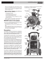
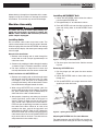
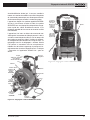
Description
The RIDGID® K-4310 FXP Drum Machine is designed to
clean various size and length drain lines depending on
size of cable being used. Applications may include floor
drains, laterals, main lines and commercial lines.
The K-4310 FXP can be used with 5/8" and ¾" diameter
cable to clean 3" to 10" drains (see specifications). All ca-
bles are equipped with a quick-change coupling system
for connecting and disconnecting tools.
The K-4310 FXP Drum Machine is powered by the FXP
Battery or FXP Power Adapter. The main ON/OFF switch
controls power to the machine and to the FOR/OFF/REV
switch which controls the motor, drum and cable rotation.
A pneumatic foot switch acts as a momentary contact
ON/OFF switch controlling the operation of the motor.
The machine is equipped with an AUTOFEED® Cable
Feed Unit that will advance or retrieve the cable. The
AUTOFEED unit includes a feature to quickly change
between cable sizes. The machine can also be used by
manually advancing and retrieving the cable.
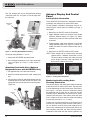
The machine is supplied with an advanced display and
control panel to allow cable information to be entered,
show real time cable travel in and out of the drum and
record job information. The K-4310 FXP Drum Machine
includes wireless technology to allow connection to smart
phones and tablets and allow easy reporting, sharing and
job logging. See “RIDGID Link App connection (Wireless
Communication)” section for details.
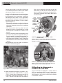
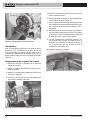
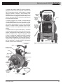
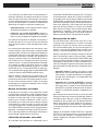
Figure 1A – RIDGID K-4310 FXP Drum Machine
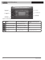
Figure 1B – RIDGID K-4310 FXP Drum Machine
5
K-4310 FXP Drum Machine
Foot Switch
Inner Drum
Handle
Advance Display and
Control Panel
Drum
AUTOFEED
Adjustment
Knob
AUTOFEED
Lever
AUTOFEED
Cable Feed Unit
Warning
Labels
Frame
Loading Wheels
Stair
Climber
Wheels
Battery
Release Latch
Serial Number
Plate
Motor
Foot Switch
Cord Wrap
FXP Battery
and FXP
Power
Adapter
Port
Cable
Handle
Release/Lock

999-995-420.10_REV A
6
K-4310 FXP Drum Machine
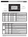
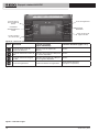
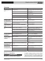
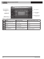
Icon Control Primary Function/Short Press Alternate Function/Long Press
(+2 sec)
Cable Travel Reset (Zero) Button Reset Cable Distance to Zero None
Cable Diameter Selector Button Set Cable Diameter from available
range None
Cable Length Selector Button Set Cable Length from available range None
Record Button Start or Stop Recording Toggle Metric/Imperial Units
Cable Travel Reset
(Zero) Button
Motor FOR/OFF/REV
Switch
Cable Diameter
Selector Button
Record Button
Figure 2A – Advance Display and Control Panel
Power ON/OFF Switch
Cable Length
Selector Button
Figure 2B – Controls Chart

999-995-420.10_REV A 7
7
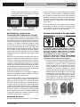
K-4310 FXP Drum Machine
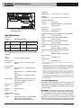
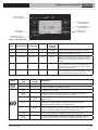
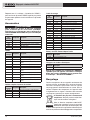
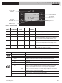
Icon Blinking Light Solid Light Meaning
Blue Connection to RIDGID Link app possible.
Blue (30s) Connection to RIDGID Link app established.
Yellow Battery charge is low and machine operation can stop anytime soon. Battery
must be recharged.
Yellow
Red
Battery low and machine will not operate. Recharge battery/insert fully charged
battery.
Yellow Maintenance is required. Consult RIDGID Link app for more information.
Red
Machine has stopped due to an event exceeding usable limits (e.g., current,
temperature, or stability). Confirm proper set-up and restart use. Consult RIDGID
Link app for more information.
Red
Machine has malfunctioned and will not operate. Remove battery and allow
Machine to rest, then reinsert battery. If light still ON, have machine serviced.
Consult RIDGID Link app for more information.
Purple Firmware update in process, machine cannot be used while updating. Consult
RIDGID Link app for more information.
Purple
Red
Firmware update was interrupted and not completed; machine cannot be used.
Continue and complete update per app instructions.
Tool Status Lights
Cable Size Selection
Recording/Time of
Recording
Figure 3 – Display/Icons
Cable Travel Indication ft/m
Cable Length Selector
Figure 5 – Tool Status Lights
Recording Active,
Selections Locked
ON/OFF
Switch FOR/OFF/REV
Switch Foot
Switch Display Tool Status
Lights Description
OFF Any Position Any Position OFF OFF Machine OFF – No power to anything
ON Any Position OFF ON ON
See Figure 5
Machine Motor OFF, Power to Display – Display set-
tings can be changed, see Figure 2A/B
ON Any Position OFF OFF OFF Machine in Hibernation Mode to reduce battery usage.
Machine will go to this mode if no user inputs for 15
minutes or more – Move ON/OFF switch to OFF and
back to ON to use
ON FOR ON ON See Figure 5 Machine will run in Forward rotation when Foot Switch
is depressed (normal operating mode, generally used
for all drain cleaning, both advancing and retrieving
cable)
ON REV ON ON See Figure 5 Machine will run in Reverse rotation when Foot Switch
is depressed (Only used for specific cases called out in
the manual)
Figure 4 – Machine Operation Modes

999-995-420.10_REV A
8
K-4310 FXP Drum Machine
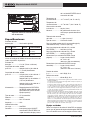
Figure 6 – Machine Serial Number - The last 4 digits of
the serial number indicate the month and year
of the manufacture
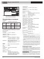
Specications
Drain Line
Capacity ............See Following Chart
See RIDGID catalog for information on specific cables
available.
Drain
Capacity ............3" to 10" (75mm to 250mm)
Drum Capacity,
5/8" Drum .......... 100' (30.5m) of 5/8" (16mm) Diameter
Cable
Drum Capacity,
3/4" Drum .......... 125' (38.1m) of 5/8" (16mm) Diameter
Cable
100' (30.5m) of 11 /16" (17.5mm) Diameter
Cable
100' (30.5m) of ¾" (20mm) Diameter
Cable
Power Supply ....RIDGID RB-FXPXX Battery Pack OR
FXP Power Adapter (See Optional
Equipment Section)
Motor Type .........Brushless DC
Watts .................810 W
Voltage ..............54V DC nominal
Amps .................15 A
No Load Output
Speed ................ 240 RPM
Controls ............. Main ON-OFF Switch, FOR/OFF/REV
Switch, Pneumatic Foot Switch,
AUTOFEED® Cable Feed Unit Lever
Operating
Temperature ...... -4° F to 140° F (-20° C to 60° C)
Storage
Temperature ...... -4° F to 140° F (-20° C to 60° C)
Wireless Connection
Range ................33 ft (10 m)
Memory .............50 Job Recordings (1 Job is approxi-
mately 2 hours)
Cable Travel
Tolerance ...........+/- 2 ft (+/- 0.6 m)**
Frame Type .......Wheeled Cart
Weight (No Cable, 3/4" Drum w/pigtail and AUTOFEED
Unit) ...................125 lbs. (63.5 kg)
Weight (w/100' of 3/4" Cable and AUTOFEED
Unit) ...................235 lbs. (113 kg)
Weight (w/100' of 5/8" Cable and AUTOFEED
Unit) ...................193 lbs. (87.5 kg)
Dimension LxWxH (no AUTOFEED Unit, Handle
down).................34" x 22" x 35"
(864mm x 559mm x 889mm)
Dimension LxWxH (w/AUTOFEED Unit, Handle
up) .....................37" x 22" x 47"
(940mm x 559mm x 1194mm)
Sound Pressure
(LPA)* .................. 84.5 dB(A), K=3
Sound Power
(LWA)* .................85.09 dB(A), K=3
* Sound measurements are measured in accordance with a standardized test per
Standard EN 62481-1.
- Sound emissions may vary due to your location and specific use of these tools.
- Daily exposure levels for sound need to be evaluated for each application and
appropriate safety measures taken when needed. Evaluation of exposure lev-
els should consider the time a tool is switched off and not in use. This may
significantly reduce the exposure level over the total working period.
** Cable Travel Tolerance – this tolerance assumes that the correct cable pa-
rameters are entered (cable diameter, cable length and drum) and that the full
cable length is in the drum (the cable end is no more than 6" (150 mm) out of
the end of the AUTOFEED cable feed unit) when the cable travel is zeroed.
Incorrect cable parameters and zeroing the cable travel with cable out of the
drum results in a greater cable travel tolerance, in some cases up to +/- 8 ft
(+/-2.5m). Cable travel does not necessarily equal distance the cable end has
traveled in the drain.
Standard Equipment
All K-4310 FXP Drum Machines comes with one pair of
RIDGID Drain Cleaning Gloves. Refer to the RIDGID cata-
log for details on equipment supplied with specific machine
catalog numbers.
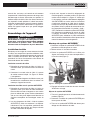
This machine is made to clean drains. If prop-
erly used it will not damage a drain that is in good condi-
tion and properly designed, constructed and maintained.
If the drain is in poor condition, or has not been properly
designed, constructed and maintained, the drain cleaning
process may not be effective or could cause damage to the
drain. The best way to determine the condition of a drain
NOTICE
Cable
Size Line Size Maximum
Reach Maximum AUTO-
FEED Unit Speed
5/8"
(16mm)
3" to 6" (75 mm
to 150 mm)
250' (61m) 25'/Min (7.6 m/min)
3/4"
(20mm)
4" to 10" (100
mm to 250 mm)
250' (61m) 28'/Min (8.5 m/min)
XXXXXMMYY

999-995-420.10_REV A 9
before cleaning is through visual inspection with a camera.
Improper use of this machine can damage the machine
and the drain. This machine may not clear all blockages.
Machine Assembly
WARNING
To reduce the risk of serious injury during use,
follow these procedures for proper assembly. The
ON/OFF switch should be OFF and battery removed/
power adapter unplugged.
Installing Cable
Do not remove cable carton straps from carton. The
cable is under tension and can whip or strike if released.
When changing cable size, the AUTOFEED® unit settings
and the advance display and control panel settings need
to be changed.
Manual Cable Installation
1. Retrieve male coupling end of cable through the
center hole of carton and pull approximately 6' of
cable from carton.
2. Connect male coupling of cable to the pigtail coupling
as shown in Figure 15. Confirm connection is secure.
3. Pull short sections of cable from the carton and
manually feed into the drum. Do not turn machine ON.
Cable Installation with AUTOFEED unit
1. Retrieve male coupling end of cable through center
hole of carton and pull cable from carton. Lay cable
out straight in a flat area (such as an empty paved
parking lot or driveway) with no obstructions or items
that could become wrapped around the cable.
2. When using AUTOFEED unit to load cable, the
rotating cable will tend to walk sideways. To prevent
this, place suitable stops (such as wood blocks) on
either side of the cable at 10-foot intervals.
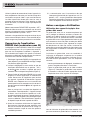
3. After properly inspecting and setting up the drain
cleaning machine, attach cable to the pigtail as
shown in Figure 15. Make sure that no one is in the
area around cable. Operate the machine/AUTO-
FEED unit per the operating instructions to retrieve
the cable into the drum. When 10' of cable is left
outside of the drum, step off the foot switch and
move the main ON/OFF switch to OFF. Loosen the
AUTOFEED knob and manually feed the remaining
cable into the drum. Do not use the AUTOFEED unit
to put entire cable in the drum. The cable end can
whip around and cause serious injury.
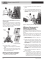
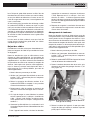
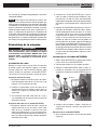
Installing AUTOFEED® Unit
1. Loosen the AUTOFEED knob to allow the cable to
pass through AUTOFEED unit.
2. Pull approximately 12" of cable from the drum.
3. Place AUTOFEED unit over the cable and align the
posts with mating holes in the AUTOFEED mount
(Figure 7).
Figure 7 – Installing the AUTOFEED Unit
4. Fully insert posts into frame holes. Confirm secured
in place.
Removing AUTOFEED Unit
1. Pull the plunger pin and open the drum retainer
(Figure 8).
2. Loosen AUTOFEED knob to allow cable to pass
through unit.
3. Pull the AUTOFEED unit straight forward to disen-
gage the pins from the frame.
Figure 8 – Opening Drum Retainer
Adjusting AUTOFEED Unit For Cable Diameter
For proper operation, the AUTOFEED unit must be ad-
justed to the correct setting for the cable it is being used
9
K-4310 FXP Drum Machine
Posts
Grease
Fitting
Plunger
Pin
Drum
Retainer

999-995-420.10_REV A
10
Advance Display And Control
Panel
Setting Cable Information
The K-4310 FXP Drum Machine is equipped to monitor
and display the cable travel in and out of the drum.
To work properly, cable/drum information must be en-
tered using the control panel (or RIDGID Link App, if
connected).
1. Move the main ON/OFF switch to ON position.
2. Toggle Between cable size selection using Cable
Diameter Selector Button (see Figure 2/3). When
selected, the screen will return to home screen after
3 seconds.
3. Toggle between cable length selection using Cable
Length Selector Button (see Figure 2/3). When se-
lected, the screen will return to home screen after 3
seconds.
4. Move the main ON/OFF switch to OFF position.
NOTE: These settings will be saved and will not need
updated unless a different drum/cable is used.
This feature does not work with cables not listed
on the display. Incorrect cable information will
decrease the cable travel accuracy.
a. Cable Diameter Screen b. Cable Length Screen
Figure 11 – Setting Cable Parameters
Monitoring And Recording Drain
Cleaning Information
The advance display and control panel allows monitoring
of the cable travel in and out of the drum. The zero point
is set by depressing the cable travel reset “Zero” button.
See Figure 2. For best results the calibration should
be performed with no more than 6" (150 mm) of cable
outside the drum. Remember that cable travel is always
relative to the zero point. If the cable is reset with more
than 6" (150 mm) out of the drum the cable travel reading
may be off by more than +/-2' (+/- 0.6 m).
Confirm that the cable information on the Control Panel
matches the cable being used. Incorrect cable informa-
tion can affect the accuracy of the travel readings. Do not
let the use or monitoring of the control panel distract you
from controlling the cable and drain cleaning process.
Inattention to the cable and drain cleaning process can
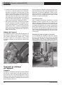
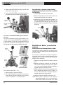
with. The setting of the unit can be checked by looking
at the front of the unit, see Figure 9. The slot aligns with
the cable size.
Figure 9 – Checking AUTOFEED Unit Setting
To change setting between 5/8" and ¾".
1. Loosen the AUTOFEED adjustment knob.
2. Use a flat blade screwdriver in cam slot to rotate both
cams (see Figure 9). If using 11 /16" cable, use the 5/8"
setting.
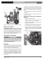
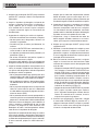
Attaching Front Guide Hose (Optional
Equipment for use with AUTOFEED Unit)
1. Pull approximately 4' of cable from the drum.
2. Slide Front Guide Hose over the cable, adapter end
first.
3. Pull plunger pin head up and place adapter over the
mounting collar on the AUTOFEED unit. Make sure
plunger pin locks into the hole in the mounting collar.
(Figure 10).
Figure 10 – Attaching Front Guide Hose
10
K-4310 FXP Drum Machine
Hole
Plunger
Pin
Adjustment
Knob
Grease
Fittings
Cam Slot
For 5/8" and 11/16" Cable
For 3/4" Cable

999-995-420.10_REV A 11
cause you to lose control and increases the risk of seri-
ous injury.
The Record button is used to start and stop recording.
Recording will also stop when ON/OFF switch is moved
to OFF position.
Recorded information includes cable travel and motor
amp draw information versus time. The K-4310 FXP Drum
Machine will hold 50 recordings. When 50 recordings are
reached, new recordings will overwrite the oldest record-
ings. Additional recordings can be stored via the RIDGID
Link App. Recorded information can be accessed and
managed through the RIDGID Link App - see the RIDGID
Link App Connection (Wireless Communication) section
for further information.
Hibernation Mode
When running on battery power, if the ON/OFF switch
is ON and the machine is not used for 15 minutes, it will
move into “Hibernation Mode” to conserve battery charge.
In Hibernation Mode, the display and tool status lights will
turn off and the machine cannot be used until the ON/
OFF switch is cycled OFF and back ON. See Figure 4.
If a Job Recording is active while the machine is in
Hibernation Mode, the in-progress recording will be saved.
When the machine is turned back ON, a new recording
will need to be started.
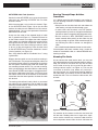
Pre-Operation Inspection
WARNING
Before each use, inspect your K-4310 FXP Drum
Machine and correct any problems to reduce the
risk of serious injury from electric shock, twisted
or broken cables, chemical burns, infections and
other causes and prevent machine damage.
Always wear safety glasses, RIDGID drain cleaning
gloves, and other appropriate protective equipment
when inspecting your machine.
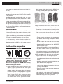
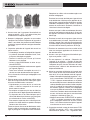
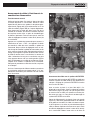
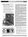
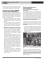
1. Inspect the RIDGID drain cleaning gloves or mitts
(“gloves”) (Figure 12). Make sure they are in good
condition with no holes, tears or loose sections that
could be caught in the rotating cable. It is important
not to wear improper or damaged gloves. The gloves
protect your hands from the rotating cable. If the
gloves are not RIDGID drain cleaning gloves or
are damaged or worn out, do not use machine
until RIDGID drain cleaning gloves are available.
Wear latex or rubber glove inside the RIDGID drain
cleaning gloves to protect against drain contents.
Figure 12 – RIDGID Drain Cleaning Gloves – Leather, PVC
2. Make sure that the main ON/OFF switch is set to the
OFF position and remove battery/power adapter.
3. Clean the drain cleaning machine, including handles
and controls. This aids inspection and helps prevent
the machine or control from slipping from your grip.
Clean and maintain the machine per the mainte-
nance instructions.
4. Inspect the machine for the following:
• Proper assembly, maintenance and completeness.
• Any broken, worn, missing, misaligned or binding
parts.
• Rotate the drum and make sure that it turns freely
without binding.
• Smooth and free movement of the AUTOFEED
lever throughout range.
• Presence and readability of warning labels (Fi gure 1).
• Any other condition which may prevent safe and
normal operation.
If any problems are found, do not use the drain clean-
ing machine until the problems have been repaired.
5. Clean any debris from the cable and cutting tools.
Inspect cables for wear and damage. Inspect for:
• Obvious flats worn into the outside of cable (cable
is made from round wire and the profile should be
round).
• Multiple or excessively large kinks (slight kinks up
to 15 degrees can be straightened).
• Space between cable coils indicating that the
cable has been deformed by stretching, kinking, or
running in reverse (REV).
• Excessive corrosion from storing wet or exposure
to drain chemicals.
All these forms of wear and damage weaken the
cable and make cable twisting, kinking or breaking
more likely during use. Replace worn and damaged
cable before using drain cleaning machine.
11
K-4310 FXP Drum Machine

999-995-420.10_REV A
12
Inspect the cable couplings for wear and damage.
Confirm that coupling plunger pins move freely and
fully extend for positive retention. If needed, lubricate
with a light oil.
Make sure the cable is fully retracted with no more
than 6" (150mm) of cable outside of the machine.
This will prevent whipping of the cable at start up.
6. Inspect the tools for wear and damage. If necessary,
replace prior to using the machine. Dull or damaged
cutting tools can lead to binding, cable breakage, and
slow the drain cleaning process.
7. Inspect and maintain any other equipment being
used per its instructions to make sure it is functioning
properly.
8. Make sure that the main ON/OFF switch is set to the
OFF position.
9. Following the Machine and Work Area Set-Up,
install a fully charged battery or power adapter into
machine. If using the power adapter, confirm that the
GFCI works correctly.
10. Following the Operating Instructions, check the ma-
chine for proper operation. No more than 6" (150
mm) of cable should be out of the machine.
• Turn the main ON/OFF switch to the ON position
and move the FOR/OFF/REV switch into the FOR
position. Press and release the foot switch and note
the direction of rotation of the drum. Let drum come
to complete stop. If the foot switch does not control
the machine operation, do not use the machine
until the foot switch has been repaired. The drum
should rotate counter-clockwise when viewed
from the front of the drum and will match the drum
direction shown on the drum in Figure 19.
• Place the FOR/OFF/REV switch into the REV
position and repeat above testing to confirm that
the drain cleaning machine operates properly in
reverse. If the rotation is not correct, do not use the
machine until it has been repaired.
11. With the inspection complete, move the FOR/OFF/
REV switch into the OFF position and turn the main
ON/OFF switch to the OFF position. With dry hands
remove battery/power adapter from the machine.
Machine and Work Area Set-Up
WARNING
Set up the K-4310 FXP Drum Machine and work
area according to these procedures to reduce the
risk of injury from electric shock, re, machine
tipping, twisted or broken cables, chemical burns,
infections and other causes, and prevent machine
damage.
Always wear safety glasses and other appropriate
protective equipment when setting up your drain
cleaning machine.
1. Check for an appropriate work area. Operate in a
clear, level, stable, dry, well-lit location. Do not use
the drain cleaning machine while standing in water.
2. Inspect the drain to be cleaned. If possible, determine
the access point(s) to the drain, the size(s) and
length(s) of the drain, distance to tanks or mainlines,
the nature of the blockage, presence of drain clean-
ing chemicals or other chemicals, etc.
If chemicals are present in the drain, it is important to
understand the specific safety measures required to
work around those chemicals. Contact the chemical
manufacturer for required information.
Confirm no other utilities are present in the drain or
area to reduce the risk of damage. Visual inspection
of the drain with a camera is a good practice.
If needed, remove fixture (water closet, etc.) to allow
access to the drain. Do not feed the cable through a
fixture. This could damage the cable and the fixture
3. Determine the correct equipment for the application.
See Specifications. Drain Cleaning Machines for
other applications can be found by consulting the
Ridge Tool Catalog, online at RIDGID.com.
Inner-Core Cable is not recommended for use
through P-Traps and severe bends in lines smaller
than 4". Optional 24" flexible trap leaders can be
added to aid users through traps and tight clean-outs.
4. Make sure all equipment has been properly in-
spected.
5. If machine is equipped with an AUTOFEED unit,
confirm that it is set to proper size for the cable being
used (see Figure 9).
K-4310 FXP Drum Machine

999-995-420.10_REV A 13
6. If needed, place protective covers in the work area.
The drain cleaning process can be messy.
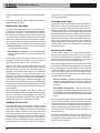
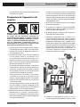
7. Transport the drain cleaning machine to the work
area along a clear path. Adjust handle if necessary
(Figure 13). Move handle latches together and move
telescoping handle to desired position. Confirm that
the handle latches engage and the handle is securely
held in position. If handle is moved past latch holes,
the handle buttons will prevent the handle from pulling
out. If this occurs, depress buttons to move handle.
Figure 13 – Adjusting Telescoping Handle
8. Position the machine so it sits squarely and firmly. The
machine cable outlet must be within 3' (0.9 m) of the
drain access.
Greater distances from the drain access increases
the risk of cable twisting or kinking. If the machine
cannot be placed within proper distance of the drain
access, extend the drain access with similar sized
pipe and fittings (See Figure 14). Improper cable
support can allow the cable to kink and twist and can
damage the cable or injure the operator.
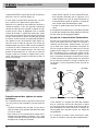
Figure 14 – Example of Extending Drain to within 3' of the
Machine Cable Outlet
9. Select proper cutting tool for the conditions.
If the nature of the obstruction is unknown, it is good
practice to use a straight or bulb auger to explore the
obstruction and retrieve a piece of the obstruction for
inspection.
Once the nature of the obstruction is known, an
appropriate tool can be selected for the application.
A good rule of thumb is to start by running the small-
est available tool through the blockage to allow the
water to start flowing and carry away the debris and
cuttings as the drain is cleaned. Once the drain is
open and flowing, other tools appropriate for the
blockage can be used. Generally, the largest tool
used should be no bigger than the inside diameter of
the drain minus one inch.
Proper tool selection depends on the specific circum-
stances of each job and is left to the user’s judgment.
A variety of other cable attachments are available
and are listed in the “Optional Equipment” section of
this manual. Other information on cable attachments
can be found in the RIDGID Catalog and online at
RIDGID.com.
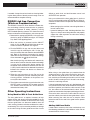
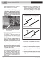
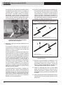
10. Securely install cutting tool on the end of the cable
(See Figure 15). If the connection is not secure, the
tool may fall off during use. As the tool is installed,
make sure that the spring-loaded plunger in the
coupling moves freely to retain the tool. If the pin
sticks in the retracted position, the tool may fall off in
use.
13
K-4310 FXP Drum Machine
Handle
Release/Lock
Handle Button
Holes
Max. 3' (0.9m)

999-995-420.10_REV A
14
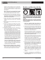
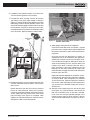
Figure 15 – Connecting/Disconnecting Cable/Tool
11. Evaluate the work area and determine if any barriers
are needed to keep bystanders away from the ma-
chine and work area. The drain cleaning process can
be messy and bystanders can distract the operator.
12. Position the foot switch for easy accessibility. You
must be able to hold and control the cable, control
the foot switch, and reach the FOR/OFF/REV switch.
13. Confirm that the FOR/OFF/REV switch is in the OFF
position and that the main ON/OFF switch is OFF.
Installing/Removing Battery or Power
Adapter
14. With dry hands, insert a fully charged battery or
power adapter into the battery port on the machine.
Do not plug power adapter in until inserted into the
machine.
The machine has a latch to secure the battery or
power adapter. The latch will engage when the
battery or power adapter is inserted. Confirm secure
by lightly pulling on the battery and ensure that it
does not separate from the tool.
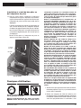
To remove the battery or power adapter, depress the
latch and slide out of the machine. See Figure 16.
Figure 16 – Battery Latch (Handle Removed for Clarity)
Operating Instructions
WARNING
Always wear eye protection to reduce the risk of
eye injury.
Always wear RIDGID drain cleaning gloves in good
condition. Latex or loose tting gloves or rags can
become wrapped around the cable and may result
in serious personal injury. Only wear latex or rubber
gloves under drain cleaning gloves. Do not use
damaged drain cleaning gloves.
Always use appropriate personal protective equip-
ment while handling and using drain cleaning
equipment. Drains may contain chemicals, bacteria
and other substances that may be toxic, infectious,
cause burns or other issues. Appropriate person-
al protective equipment always include safety
glasses and drain cleaning gloves, and may include
equipment such as latex or rubber gloves, face
shields, goggles, protective clothing, respirators
and steel toed footwear.
Do not allow the cutter to stop turning while the
machine is running. This can overstress the cable
and may cause twisting, kinking or breaking of
the cable. Twisting, kinking or breaking cable may
cause striking or crushing injuries.
Keep glove covered hand on the cable whenever
K-4310 FXP Drum Machine
Battery Latch
Battery
Connecting
Keep couplings clean and lubricated. Plunger pin must
move freely and fully extend to secure connection.
Disconnecting - Using Pin Key
1. Slide the couplings together.
2. Confirm connection is secure. (Plunger pin fully extended.)
1. Fully insert pin key (rotate, if needed) to depress the plunger pin.
2. Slide couplings apart.
12
21

999-995-420.10_REV A 15
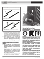
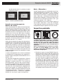
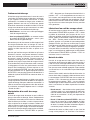
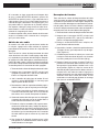
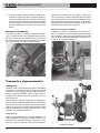
Figure 17 – Proper Operating Position
3. Move the ON/OFF switch to the ON position. Move
the FOR/OFF/REV switch to the FOR (FORWARD)
position. Do not depress the foot switch yet. “FOR”
and “REV” refers to the drum/cable rotation and not
to the direction of cable movement. Do not rotate
the cable in REV (reverse) except as specifically
described in these instructions. Running the machine
in REV can damage the cable.
Figure 18 – Cable Movement in FOR (Forward Rotation)
NOTE: If Machine is set for REV (Reverse Rotation) AUTO-
FEED advance and retrieve direction are opposite.
the machine is running. This provides better control
of the cable and helps prevent twisting, kinking and
breaking of the cable. Twisting, kinking or breaking
cable may cause striking or crushing injuries.
Position machine cable outlet within 3' (0.9 m) of
the drain inlet or properly support exposed cable
when the distance exceeds 3' (0.9 m). Greater dis-
tances can cause control problems leading to
twisting, kinking or breaking of the cable. Twisting,
kinking or breaking cable may cause striking or
crushing injuries.
One person must control both the foot switch and
cable. If the cutter stops rotating, the operator
must be able to release the foot switch to pre-
vent twisting, kinking and breaking of the cable.
Twisting, kinking or breaking cable may cause
striking or crushing injuries.
Follow operating instructions to reduce the risk of
injury from twisted or broken cables, cable ends
whipping around, machine tipping, chemical burns,
infections and other causes.
1. Make sure that machine and work area is properly
set-up and that the work area is free of bystanders
and other distractions.
2. Pull cable out of drum and feed into drain. If needed,
loosen AUTOFEED knob. Push cable as far into drain
as it will go. At least one foot (.3 m) of cable must be
in drain so that the end of the cable will not come out
of the drain and whip around when the machine is
started.
Directly route the cable from the outlet of machine
to the drain opening, minimizing exposed cable and
changes in direction. Do not tightly bend the cable
– this can increase the risk of twisting or breaking.
Assume a proper operating position to help maintain
control of the cable and machine (see Figure 17):
• Be sure you can control the ON/OFF action of the
foot switch and can quickly release the foot switch
if needed. Do not press foot switch yet.
• You must be able to place at least one RIDGID
drain cleaning glove covered hand on the cable to
always control and support the cable.
• Be sure that you have good balance, do not have
to overreach, and cannot fall on the foot switch,
machine, the drain or other hazards.
• You must be able to reach the main ON/OFF switch
and FOR/OFF/REV switch.
This operating position will help to maintain control of
the cable and machine.
15
K-4310 FXP Drum Machine
Max. 3' (0.9m)
AUTOFEED
Lever
AUTOFEED
Retrieve AUTOFEED
Advance FOR (Forward
Rotation)
Cable
Advance
Cable
Retrieve
AUTOFEED
Knob

999-995-420.10_REV A
16
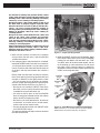
Figure 19 – AUTOFEED Lever Positions (Cable Turning In
FOR Direction)
NOTE: Rate of cable advance or retrieve varies by handle
movement from neutral.
K-4310 FXP Drum Machine
Operation
When using the K-4310 FXP Drum Machine, cable can
be fed either manually or using the AUTOFEED unit.
Generally, you can switch back and forth between oper-
ating methods as needed.
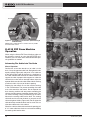
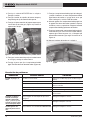
Advancing The Cable Into The Drain
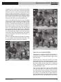
Manual Operation
Confirm that at least one foot (0.3 m) of cable is in the
drain. Grasp the exposed cable with both gloved hands
equally spaced (Figure 20A) and pull 6"-12" of cable out
of the drum (Figure 20B) so that there is a slight bow in
the cable. Gloved hands must be on cable to control and
support the cable. Improper cable support can allow the
cable to kink or twist and can damage cable or injure the
operator. Make sure that the cable outlet of drain cleaning
machine is within 3' (0.9 m) of the drain opening.
Depress the foot switch to start the machine rotating
in the FOR direction. The person controlling the cable
must also control the foot switch. Do not operate the
drain cleaning machine with one person controlling the
cable and another person controlling the foot switch. This
can lead to twisting, kinking and breaking of the cable.
Advance the rotating cable into the drain. The rotating
cable will work its way into the drain as you push on the
cable with gloved hands (Figure 20C). Do not allow the
cable to build up outside the drain, bow or curve. This can
allow the cable to twist, kink or break.
When the cable has been fed into the drain opening, pull
6"-12" more cable from the drum and continue feeding
the rotating cable into the drain.
Figure 20A,B,C – Manual Feed Operation
K-4310 FXP Drum Machine
A
C
B
FOR
(FORWARD
ROTATION)
FULL RETRIEVE
FULL RETRIEVE FULL ADVANCE
FULL ADVANCE
NEUTRAL
NEUTRAL
AUTOFEED
UNIT LABEL

999-995-420.10_REV A 17
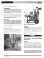
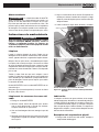
Passing Through Traps Or Other
Transitions
If it is difficult to get the cable through a trap or other fit-
ting, the following methods or combinations of methods
can be used.
• Sharp thrusts of the cable, both with and without the
cable rotating, can help the cable through a trap.
• In some cases, with the switch in the OFF position,
rotating the drum by hand can change the orientation of
the cutter to allow it to negotiate the fitting more easily.
• Run the machine in REV (REVERSE) rotation for
several seconds while pushing on the cable. Only do
this long enough to get the cable started through the
trap. Running the cable in reverse can damage the
cable.
• Use a flexible leader between the tool and the cable.
If these options don’t work, consider using a smaller di-
ameter or more flexible cable, or a different RIDGID drain
cleaning machine.
Cleaning The Drain
As you advance the cable into the drain, you may see
the cable slow down or build up outside the drain. Always
keep your hands on the cable. You may feel the cable
start to wind or load up (this may feel like the cable is
starting to twist or squirm, see Figure 22.) This may be
a transition in the drain (trap, elbow, etc.), build up in
the drain (grease, etc.) or the actual blockage. Advance
the cable slowly and carefully. Do not let cable build up
outside the drain. This can cause the cable to twist, kink
or break.
Figure 22 – Cable Shape When Unloaded, Loaded
Pay attention to the amount of cable that has been fed
into the drain. Feeding cable into a larger drain, septic
tank or similar transition may cause the cable to kink or
knot and prevent removal from the drain. Minimize the
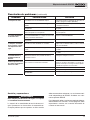
AUTOFEED Cable Feed Operation
Confirm that the AUTOFEED unit is set up for the correct
cable size, see “Adjusting AUTOFEED Unit For Cable
Diameter” section.
With at least one foot (.3 m) of cable is in the drain. Tight-
en the AUTOFEED knob (Figure 18) so that the roller
touches the cable plus one additional turn. Do not over-
tighten the knob – this can cause premature failure of the
AUTOFEED unit or cable.
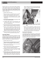
Grasp near the center of the exposed length of cable
with a gloved hand (Figure 21). Gloved hand must be
on the cable to control and support the cable. Improper
cable support can allow the cable to kink or twist and can
damage the cable or injure the operator. Make sure that
the cable outlet of the drain cleaning machine is within
3' (0.9 m) of the drain opening. Place the other hand
on the AUTOFEED lever. The lever should be in neutral
(Vertical) position (see Figure 19).
See “Using Machine With A Front Guide Hose” if using
a guide hose.
Depress the foot switch to start the machine rotating in
the FOR direction. The person controlling the cable must
also control the foot switch. Do not operate the machine
with one person controlling the cable and another per-
son controlling the foot switch. This can lead to twisting,
kinking and breaking of the cable. With the cable rotating,
move the AUTOFEED control lever in the opposite direc-
tion that the cable rotates (See Figure 19). This will cause
the cable to advance out of the machine. The further the
control lever from the neutral position, the faster the cable
will advance.
The rotating cable will work into the drain as you control
the cable with your gloved hand. Do not allow the cable
to build up outside the drain, bow or curve. This can allow
the cable to twist, kink or break.
Figure 21 – Operating using the AUTOFEED Unit
17
K-4310 FXP Drum Machine
Drain
UNLOADED LOADED
Machine

999-995-420.10_REV A
18
amount of cable fed into the transition to prevent prob-
lems.
If an additional length of cable is needed, see the section
“Adding Additional Cable”.
Working The Blockage
If the end of the cable stops turning, it is no longer clean-
ing the drain. If the end of the cable becomes lodged in
the blockage and power is maintained to the machine,
the cable will start to wind up (this may feel like the cable
is starting to twist or squirm). Having a hand on the cable
allows you to feel this wind up and control the cable. If
the cable end stops turning or if the cable starts to wind
up, immediately pull the cable back from the obstruction:
• Manual Operation – pull back on the cable to free the
cable end from the blockage.
• AUTOFEED Unit Operation – move the AUTOFEED
lever to retrieve direction to free the cable end of the
blockage.
Do not keep the cable rotating if the cable is stuck in a
blockage. If the cable end stops turning and the drum
keeps rotating, the cable can twist, kink or break.
Once the cable end is free of the blockage and turning
again, you can slowly feed the cable end back into the
blockage. Do not try to force the cable end through the
blockage. Let the spinning end “dwell” in the blockage
to completely break it up. Work the tool in this manner
until you have moved completely past the blockage (or
blockages) and the drain is flowing. Manual operation is
usually the best choice if the cable repeatedly gets stuck
when using the AUTOFEED unit. If using an AUTOFEED
unit machine manually, the AUTOFEED knob may need
to be loosened, and the AUTOFEED lever placed in the
neutral position.
While working the blockage, the cable and tool may
become clogged with debris and cuttings from the block-
age. This can prevent further progress. The cable and
tool need to be retrieved from the drain and the debris
removed. See section on “Retrieving the Cable”.
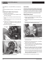
Handling A Stuck Tool
If the tool stops turning and the cable cannot be pulled
back from the blockage, immediately release the foot
switch while firmly holding the cable. Do not remove
hands from cable or cable may kink, twist and break.
The motor will stop and the cable and drum may turn
backwards until the energy stored in the cable is relieved.
Do not remove hands from cable until the tension is
released. Place FOR/OFF/REV switch in OFF position.
Do not move the main ON/OFF switch to OFF position if
recording, this will cause a data interruption and may not
allow chart generation.
Freeing A Stuck Tool
If the tool is stuck in the blockage, with the FOR/OFF/
REV switch in the OFF position and the foot switch re-
leased, try pulling the cable loose from the blockage. If
the tool will not come free from the blockage, place the
FOR/OFF/REV switch in REV position. Grasp the cable
with both gloved hands, press the foot switch for several
seconds and pull on the cable until it is free of the block-
age. Do not operate the machine in the REV position any
longer than required to free (unscrew) the cutting tool
from the blockage or cable damage can occur. Place the
FOR/OFF/REV switch in the FOR position and continue
cleaning the drain.
Retrieving The Cable
Once the drain is open, start a flow of water down the
drain to flush the debris out of the line. This can be done
by running a hose down the drain opening, turning on a
faucet in the system or other methods. Pay attention to
the water level, as the drain could plug again.
With water flowing through the drain, retrieve the cable
from the line. The flow of water will help to clean the cable
as it is retrieved. The FOR/OFF/REV switch should be
in the FOR position – do not retrieve the cable with the
switch in the REV position, this can damage the cable.
As with feeding the cable into the drain, cables can be
caught while being retrieved.
• Manual Operation – With both gloved hands equally
spaced on the exposed cable for control, pull 6”-12”
lengths of cable from the drain at a time and feed it into
the drum.
• AUTOFEED Unit Operation – With one hand near
the center of the exposed length of cable, move the
AUTOFEED lever to the retrieve position. The rotating
cable will work its way out of the drain and back into the
drum.
Continue retrieving cable until the cable end is just inside
the drain opening. Release the foot switch and allow the
machine to come to a complete stop. Do not pull the end
of the cable from the drain while the cable is rotating. The
cable can whip around and cause serious injury. Pay at-
tention to the cable during retrieval as the cable end can
still become stuck.
Place the FOR/OFF/REV switch in the OFF position. Pull
the remaining cable from the drain with gloved hands
and feed back into the machine. Place the main ON/OFF
switch in the OFF position.
K-4310 FXP Drum Machine
La page est en cours de chargement...
La page est en cours de chargement...
La page est en cours de chargement...
La page est en cours de chargement...
La page est en cours de chargement...
La page est en cours de chargement...
La page est en cours de chargement...
La page est en cours de chargement...
La page est en cours de chargement...
La page est en cours de chargement...
La page est en cours de chargement...
La page est en cours de chargement...
La page est en cours de chargement...
La page est en cours de chargement...
La page est en cours de chargement...
La page est en cours de chargement...
La page est en cours de chargement...
La page est en cours de chargement...
La page est en cours de chargement...
La page est en cours de chargement...
La page est en cours de chargement...
La page est en cours de chargement...
La page est en cours de chargement...
La page est en cours de chargement...
La page est en cours de chargement...
La page est en cours de chargement...
La page est en cours de chargement...
La page est en cours de chargement...
La page est en cours de chargement...
La page est en cours de chargement...
La page est en cours de chargement...
La page est en cours de chargement...
La page est en cours de chargement...
La page est en cours de chargement...
La page est en cours de chargement...
La page est en cours de chargement...
La page est en cours de chargement...
La page est en cours de chargement...
La page est en cours de chargement...
La page est en cours de chargement...
La page est en cours de chargement...
La page est en cours de chargement...
La page est en cours de chargement...
La page est en cours de chargement...
La page est en cours de chargement...
La page est en cours de chargement...
La page est en cours de chargement...
La page est en cours de chargement...
La page est en cours de chargement...
La page est en cours de chargement...
La page est en cours de chargement...
La page est en cours de chargement...
La page est en cours de chargement...
La page est en cours de chargement...
La page est en cours de chargement...
La page est en cours de chargement...
La page est en cours de chargement...
La page est en cours de chargement...
La page est en cours de chargement...
La page est en cours de chargement...
La page est en cours de chargement...
La page est en cours de chargement...
La page est en cours de chargement...
La page est en cours de chargement...
-
 1
1
-
 2
2
-
 3
3
-
 4
4
-
 5
5
-
 6
6
-
 7
7
-
 8
8
-
 9
9
-
 10
10
-
 11
11
-
 12
12
-
 13
13
-
 14
14
-
 15
15
-
 16
16
-
 17
17
-
 18
18
-
 19
19
-
 20
20
-
 21
21
-
 22
22
-
 23
23
-
 24
24
-
 25
25
-
 26
26
-
 27
27
-
 28
28
-
 29
29
-
 30
30
-
 31
31
-
 32
32
-
 33
33
-
 34
34
-
 35
35
-
 36
36
-
 37
37
-
 38
38
-
 39
39
-
 40
40
-
 41
41
-
 42
42
-
 43
43
-
 44
44
-
 45
45
-
 46
46
-
 47
47
-
 48
48
-
 49
49
-
 50
50
-
 51
51
-
 52
52
-
 53
53
-
 54
54
-
 55
55
-
 56
56
-
 57
57
-
 58
58
-
 59
59
-
 60
60
-
 61
61
-
 62
62
-
 63
63
-
 64
64
-
 65
65
-
 66
66
-
 67
67
-
 68
68
-
 69
69
-
 70
70
-
 71
71
-
 72
72
-
 73
73
-
 74
74
-
 75
75
-
 76
76
-
 77
77
-
 78
78
-
 79
79
-
 80
80
-
 81
81
-
 82
82
-
 83
83
-
 84
84


RIDGID Máquinas a tambor K-4310 FXP Manuel utilisateur
- Catégorie
- Outils électroportatifs
- Taper
- Manuel utilisateur