STEMCO 21195 Dial Indicator Assembly And User Instructions
- Taper
- Assembly And User Instructions

Fig. 4
Dial Indicator Assembly and User Instructions
Dial Indicator Assembly and User Instructions
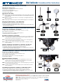
Dial Indicator Components
The following piece are included in the Dial Indicator Assembly Kit:
◼Magnetic Base and Stand (Figure 1)
◼Cross Bar and Slider with Thumbscrew (Figure 2)
◼Dial indicator gauge (Figure 3)
Dial Indicator Assembly
STEP 1. Attach the stand to the magnetic base by threading the set nut onto the stand as far as it will
go (do not tighten). Insert the stand into the magnetic base and hand tighten. Tighten the set
nut against the base.
STEP 2. Attach the cross bar and slider to the base as shown in Figure 4, and tighten thumbscrew to
hold cross bar in place.
STEP 3.
Using the gauge attachment screw (Figure 4), attach the dial Indicator gauge to the cross bar (Figure 5).
Mounting the Dial Indicator on the Wheel End
The STEMCO Dial Indicator can be mounted to the wheel end in two ways:
◼Attach it to the spindle end using the magnetic base (see Figure 6).
◼Attach to the spindle end by removing the base (Figure 7) and screwing the threaded shaft into the
hubcap mounting holes (Figure 8).
Ensamble del Indicador de Carátula e instrucciones para el usuario
Componentes del Indicador de Carátula
Las siguientes piezas están incluidas en el kit de ensamble del indicador de carátula:
◼Base magnética y soporte (Figura 1)
◼Barra transversal y deslizador con tornillo de mariposa (Figura 2)
◼Calibrador del Indicador de carátula (Figura 3)
Ensamble del Indicador de Carátula
PASO 1. Una el soporte a la base magnética atornillando la tuerca sobre el soporte hasta la posición
en que debe quedar (no apretar.) Inserte el soporte en la base magnética y apriete con la
mano. Fije la tuerca contra la carcasa y apriete bien
PASO 2. Coloque la barra transversal y la pieza deslizante en la base como se muestra (Figura 4),
y apriete el tornillo de mariposa para mantenerlo en su lugar.
PASO 3. Utilizando el tornillo de fijación del calibrador (Figura 4), afiance el calibrador en la barra
transversal (Figura 5)
Montaje del Indicador de Carátula en el Extremo de la Rueda
El indicador de carátula STEMCO se puede montar en el extremo de la rueda de dos maneras:
◼Ase
guránd
olo al extremo del eje con la base magnética
(consulte la Figura 6)
.
◼Asegurándolo al extremo del eje quitando la base (Figura 7) y atornillando la barra roscada en los
orificios de montaje de la tapa de la maza (Figura 8).
Ensemble d’indicateur à cadran et instructions d’utilisation
Composants d’Indicateur à Cadran
Les pièces suivantes font partie du kit d’ensemble d’indicateur à cadran :
◼Base magnétique et support (Figure 1)
◼Barre transversale et glissière avec vis à serrage à main (Figure 2)
◼Cadran indicateur (Figure 3)
Ensemble d’Indicateur à Cadran
ÉTAPE 1. Pour fixer le support à la base magnétique, visser complètement le contre-écrou sur le
support (ne pas serrer). Insérer le support dans la base magnétique et serrer à la main.
Serrer le contre-écrou sur le boîtier et fixer le tout solidement.
ÉTAPE 2. Fixer la barre transversale et la glissière à la base comme indiqué (Figure 4), puis serrer la vis
à serrage à main pour maintenir en place.
ÉTAPE 3. À l’aide de la vis de fixation de l’indicateur (Figure 4), fixer le cadran indicateur à la barre
transversale (Figure 5).
Assemblage de l’Indicateur à Cadran sur l’Extrémité de Roue
L’indicateur à cadran STEMCO peut être assemblé à l’extrémité de roue de deux façons :
◼On peut le fixer à l’extrémité de la fusée à l’aide de la base magnétique (voir Figure 6).
◼On peut également le fixer à l’extrémité de la fusée en retirant la base (Figure 7) et en vissant la
tige filetée dans les trous de montage du couvre-moyeu (Figure 8).
Fig. 5
Fig. 3Fig. 2
Fig. 6
Fig. 8 Fig. 7
Screw into Hubcap
Mounting Holes
Tornillo en
agujeros de
montaje de tapa
de la maza
Visser dans les
trous du chapeau
de moyeu
Fig. 1
Making the Roadways Safer®
For more information, visit stemco.com, see your STEMCO Representative or call 1-800-527-8492.
STEMCO - USA 300 Industrial Drive – Longview, TX 75602 • (903) 758-9981 • 1-800-527-8492 • FAX: 1-800-874-4297
STEMCO - Canada 5775 McLaughlin Road – Mississauga, ON L5R 3P7 • (905) 206-9700 • 877-232-9111 • FAX: 877-244-4555
STEMCO is registered trademark of STEMCO Products, Inc. © 2019 STEMCO Products, Inc.
Printed in the USA • FB 21195 • REV.: 10/2019
www.stemco.com
Thumbscrew
Tornillo de
mariposa
Vis à serrage
à main
Gauge
Attachment
Screw
Tornillo de
fijación del
Calibrador
Vis de
fixation de
l’indicateur
-
 1
1

STEMCO 21195 Dial Indicator Assembly And User Instructions
- Taper
- Assembly And User Instructions
dans d''autres langues
- English: STEMCO 21195 Dial Indicator
- español: STEMCO 21195 Dial Indicator
Documents connexes


Autres documents
-
DeWalt D25773K Manuel utilisateur
-
-
 Craftmade Accolade TH003 Assembling Instructions
-
-
 Ridgeway Grandfather Manuel utilisateur
-
 Ridgeway Grandfather Manuel utilisateur
-
-
-
Gardner Bender GMT-12A Le manuel du propriétaire


