Soozier A91-132 Mode d'emploi
- Catégorie
- Fitness, gymnastique
- Taper
- Mode d'emploi

IN221001978V01_US_CA
A91-132
EN
MANUALE D'USO
IMPORTANT, RETAIN FOR FUTURE REFERENCE: READ CAREFULLY
INSTRUCTION MANUAL

Country Phone Email
001-877-644-9366 customerservice@aosom.comUS
416-792-6088 customerservice@aosom.ca
CA
Dear customer,
Thank you for purchasing this product. So that your appliance serves you well, please
read all the instructions in this user's manual. If you have any questions, please contact
our customer care center.
Our contact details are below:

④1
③1
②1
①1
⑧1
⑦1
1 2 2
1 1 4
2 1 1
1
BOX - 1/4

⑩2
⑨1
⑥1
⑤1
1 2
1 1 1
2 1 2
1 1 1
2 4 2
12 8
1 1
1
5 1
2
Hardware Kit
BOX - 2/4

1 2
1 1
4
5
BOX - 3/4
BOX - 4/4

1
Contents
Safety Information 2
Components - Parts 3-5
Components – Fixings 6
Assembly Instructions 7-21
Workout area 22
Exercise Information 24-34
Before starting 23
Muscle chart 24
Warming up and cooling down 25-26
Use the home gym 27-29
Home gym adjustment 30
Care and Maintenance 31
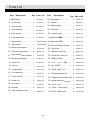
Parts List 32-33

2
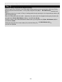
Safety Information
Important – Please read fully before assembly or use
This exercise equipment is built for optimum safety. However, certain precautions apply whenever you
operate a piece of exercise equipment. Be sure to read the entire manual before you assemble, operate
or use this equipment.
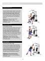
Assembly
• The product must be installed on a stable and
level surface. To protect the floor or carpet
from damage, place a mat under the home
gym.
•Assemble the item as close to its final position
(in the same room) as possible.
• Make sure you have enough space to layout the
parts before starting.
• Keep children and animals away from the exercise
area, small parts could pose a choking hazard if
swallowed.
• Dispose of all packaging carefully and responsibly.
• Check you have all the components and tools
listed in the parts list, bearing in mind that, for
ease of assembly, some components are pre-
assembled.
• The assembly of this equipment is best carried
out by 2 people.
Use
• It is the responsibility of the owner to ensure that
all users of this product are properly informed as to
how to use this product safely.
• This product is intended for domestic use only.
Do not use in any commercial, rental, or institutional
setting.
•Use the equipment only for intended use, as
described in this manual. Do not use attachments
not recommended by the manufacturer.
• Keep this equipment indoors, away from
moisture and dust. Do not put the equipment in a
garage, outbuilding, covered patio, or near water.
• Your product is intended for use in clean dry
conditions. You should avoid storage in excessively
cold or damp places as this may lead to corrosion
and other related problems that are outside our
control.
• Keep unsupervised children away from the
equipment.
• Parents and others in charge of children should be
aware of their responsibility because the natural play
instinct and the fondness of experimenting of
children can lead to situations and behavior for
which the training equipment is not intended.
• If children are allowed to use the equipment under
supervision, their mental and physical development
should be taken into account. They should be
controlled and instructed to the correct use of the
equipment. The equipment is under no
circumstances suitable as a toy.
• Disabled persons should not use the equipment
without a qualified person or doctor in attendance.
• Always wear appropriate workout clothing when
exercising. Do not wear loose or baggy clothing,
as it may get caught in the equipment. Wear
trainers to protect your feet while exercising.
•Do not place any sharp objects around
the equipment.
• Keep hands away from all moving parts.
• If any of the adjustment devices are left projecting,
they could interfere with the user’s movement.
• Before using the equipment to exercise, always
perform stretching exercises to properly warm up.
• Only one person at a time should use the
equipment.
• A spotter is recommended during exercise.
• If the user experiences dizziness, nausea, chest
pain, or other abnormal symptoms stop the
workout and seek immediate medical attention.
• Injuries to health may result from incorrect or
excessive training.
• This product is suitable for a maximum user
weight of: 120kg.
• The maximum training mass is 25 kg (99LB) (i.e.
the total additional weight used for your workout).
• This product conforms to: BS EN ISO 20957-1
and BS EN957-2 Class (H) - Home Use
Warning: Before beginning any exercise program, consult your Doctor. This is especially important
for persons over the age of 35 or persons with pre-existing health problems. You MUST read all
instructions before using any fitness equipment. Argos and its associates assumes no responsibility
for personal injury or property damage sustained by or through the use of this product.
4

3
MUST read all instructions before using any fitnes
n
j
ur
y
or
p
ro
p
ert
y
dama
g
e sustained b
y
or throu
g
h
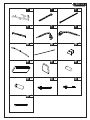
Components - Parts
Please check you have all parts listed below
Note: Some of the smaller components may be pre-fitted to larger components. Please check carefully
before contacting Argos regarding any missing components.
The total mass of the product is 74 kg.
1. Base frame × 1 2. Upper frame × 1 3. Vertical frame × 1
4. Rear stabilizer × 1 5. Front support × 1 6. Front press base × 1
7. Right butterfly × 1 8. Left butterfly × 1 9. Preacher pad
support × 1
10. Floating pulley
bracket × 2
11. Angle double
pulley bracket × 1
12. Swivel pulley
bracket × 2
13. Select rod × 1 14. Lat bar × 1 15. Leg developer × 1 16. Front stabilizer × 1

4
Please check you have all parts listed below
17. Foam roller tube × 2 18. Guide rod × 2 19.
20. 21. Rear stabilizer end
cap × 2
22. Rear beam-1
23. Pull bar × 1 24. Backrest pad × 1 25. Seat pad × 1
26. Preacher pad × 1 27.Metal sleeve φ18x2 28.Metal sleeve φ25x4
29. Ø61mm Rubber
bumper × 2 30. Lock knob × 1 31. Ø60mm Foam
roller × 4
32. Ø10mm Foam roller × 2 33. Ø90mm Pulley
× 12
34.Plate support
0Ø55 × 1
Bracing tubeX1
handrail-X2

5
Please check you have all parts listed below
35.PinX2 36. Cover ringX1 37.Pulley bushing 16x8
φ10X55 φ40X3
38. Seated press lock
pin × 1 φ10X60
39. Weight select pin
× 1 φ10X140
41. KGSelect
plate × 1 42. Weight
plate × 9
43. mm Lower
cable × 1
44. 3020mm Upper
cable × 1 45. 2250mm Butterfly
cable × 1
54. 4.5KG
φ
4030

6
Components - Fixings
Please check you have all fixings listed below
Note: The quantities below are the correct amount to complete the assembly. In some cases more
hardware may be supplied than are required. Some of the fixings are pre-fitted to the larger components.
Please check carefully before contacting Argos regarding any missing fixings.
50
M10×70 Bolt×6
51
M10×60 Bolt×2
52
M10×75 Bolt×1
53
M10×40 Bolt×9
55
M10×25 Bolt×6
56
M8
×
60 Bolt
×
2
57
M8×20 Bolt×2
58
M12×85 Long bolt×1
59
M10×40 B olt×2
60
Washer×6
61
φ10 Washer×64
62
φ12 Washer×4
63
M10 Nut×30
64
M12 Nut×3
65
Joint chain × 2
66
67
6# Clip hook × 5
M8×45 Bolt ×2
φ8
68
spannerx1
49
M10×65 Bolt×10

7
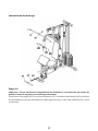
Assembly instructions
Step 1
Attach rear of the base frame (1) to
the Rear stabilizer (4). Fix using M10
×65bolts( 49),Φ10 Washers (61)
and M10 nuts (63)
Insert the Guide rods (18) into the
holes on the Rear stabilizer (4).
Slide 61mm Rubber bumpers (29)
down onto Guide rods (18).
29 29
18 18
21
1
61 63
4
21
49
1
× 4×
× 2
× 2
Fully tighten bolts.
Align the holes.
Note-The two M10X60 bolts(50)should be put
through the holison Guide Rods(18)as well.
.

8
Assembly instructions
63
1
49
63 49
5
59
Step 2
61
Attach the Frot support(5)
to the Base frame(1) with
M10x65 Bolt(49)x2and 10
Washer(61)x4andM10 Nut(63)x2
Attach the Front stabilizer(16)to the
Front support(5)withM10X40
(61)X2
φ
Bolt(59)X2andM10 Nut(63)X2and Washer
61
16
61

Assembly instructions
9
Carefully slide Weight plates (42) down Guide rods (18).
Important:
The deep grooves on the Weight plates (42)MUST be on the underside.
Insert the Select rod down through the centre holes of the weight stack. Slide the Plate support (34)
down and attach it to the first hole from the top with the Pin (35). Ensure the Plate support
(34)and Pin (35)the top Weight plate
.
Put the Cover ring(36) on the top of the Select plate(41).
Slide Select plate (35) down Guide rods (18).
When using: Select the desired training weight by inserting the Weight select pin (39) into the deep
grooves under the Weight plates and into the Select rod.
When not in use: Insert the Weight selection pin (39) into
stabilizer (4).
2
.
36
34
35
41
13
39
42
Step 3
on
(13)
the Select rod(13)
sit (42)
the hole on the Rear bracket(19)attached to the
Rear

Assembly instructions
10
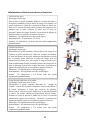
Attach the Vertical frame (3) to the Base frame (1). Fix using M10×70 bolts (50),M10 Washers (61)
and M10 Nuts (63)
.
Fully tighten bolts.
Step 4
x2 x2
x4
.
1 61 50
19
1
61
50
49
3
63
61
63
M10×65 bolts (49),
x2 M10 Washers (61)and M10 Nuts (63)
.
x2
x4
.

Assembly instructions
11
A
ttach the Upper frame(2) to the Rear beam(22) with M10×65 Bolt and M10
Nut(63)
A
ttach Upper frame (2) to Vertical frame (3) with ,φ
10Washer (61) and M10 Nut
(63)
the Rear beam (22) to the Guide rods (18) with M10×25 Bolt (55) .
Step 5
x2 Washer (61) x2
(49) x2.Washer (61) x4.
x2 x4.
x2.
A
ttach
261
3
55
63
49
49
M10×65 Bolt (49) x2
22

Assembly instructions
12
Put 2Metal sleeve (27) into the hole on the both sides of the Upper frame(2).
Attach the Front press base (6)to the Upper frame (1)using the Long bolt (58).Washers (62)
and M1 Nuts (6).
Step 6
24x1
.
x1 x2.
M12
6
62
27
64 27
58

Assembly instructions
13
Place Metal sleeve (28)in the holes on the Front press base (6). Attach the Right and Left Butterfly’s
(7 & 8) to the Front press base (6) using 12 Washers (62)and M12 Nuts (64)
.
Slide mm Foam rollers (3) the end of the Butterfly s (7 & 8).
VI
38
6
8
Step 7
2
x4 .x2 x2
100 from
64
62
28
28
7
32
38
6
8

Assembly instructions
14
Attach the Backrest pad (24) to the Vertical frame (3) using M8 × 50mm bolts (56)and M8 Washers (60).
Attach the Seat pad (25) to the Base frame (1) using M8 bolts (66)and M8 Washers (60).
60 56
60
56
24
25
60 66
Step 8
x2
x2.
x2 x2
3
1

Assembly instructions
15
Slide the Foam roller tubes (17) half way into the holes on the Base frame (1) and Leg developer (15).
Push 4 × 60mm Foam rollers (31) onto each side of the Foam roller tubes (17).
Attach the Leg developer (15) to the Base frame(1) using M10 bolts (52)and M10
Nuts (63).
15
31
31 17
63
15
17 52 31
31
Step 9
61
x1 Washers (61).
x2
.
x1
1
La page est en cours de chargement...
La page est en cours de chargement...
La page est en cours de chargement...
La page est en cours de chargement...
La page est en cours de chargement...
La page est en cours de chargement...
La page est en cours de chargement...
La page est en cours de chargement...
La page est en cours de chargement...
La page est en cours de chargement...
La page est en cours de chargement...
La page est en cours de chargement...
La page est en cours de chargement...
La page est en cours de chargement...
La page est en cours de chargement...
La page est en cours de chargement...
La page est en cours de chargement...
La page est en cours de chargement...
La page est en cours de chargement...
La page est en cours de chargement...
La page est en cours de chargement...
La page est en cours de chargement...
La page est en cours de chargement...
La page est en cours de chargement...
La page est en cours de chargement...
La page est en cours de chargement...
La page est en cours de chargement...
La page est en cours de chargement...
La page est en cours de chargement...
La page est en cours de chargement...
La page est en cours de chargement...
La page est en cours de chargement...
La page est en cours de chargement...
La page est en cours de chargement...
La page est en cours de chargement...
La page est en cours de chargement...
La page est en cours de chargement...
La page est en cours de chargement...
La page est en cours de chargement...
La page est en cours de chargement...
La page est en cours de chargement...
La page est en cours de chargement...
La page est en cours de chargement...
La page est en cours de chargement...
La page est en cours de chargement...
La page est en cours de chargement...
La page est en cours de chargement...
La page est en cours de chargement...
La page est en cours de chargement...
La page est en cours de chargement...
La page est en cours de chargement...
La page est en cours de chargement...
La page est en cours de chargement...
La page est en cours de chargement...
La page est en cours de chargement...
La page est en cours de chargement...
La page est en cours de chargement...
La page est en cours de chargement...
-
 1
1
-
 2
2
-
 3
3
-
 4
4
-
 5
5
-
 6
6
-
 7
7
-
 8
8
-
 9
9
-
 10
10
-
 11
11
-
 12
12
-
 13
13
-
 14
14
-
 15
15
-
 16
16
-
 17
17
-
 18
18
-
 19
19
-
 20
20
-
 21
21
-
 22
22
-
 23
23
-
 24
24
-
 25
25
-
 26
26
-
 27
27
-
 28
28
-
 29
29
-
 30
30
-
 31
31
-
 32
32
-
 33
33
-
 34
34
-
 35
35
-
 36
36
-
 37
37
-
 38
38
-
 39
39
-
 40
40
-
 41
41
-
 42
42
-
 43
43
-
 44
44
-
 45
45
-
 46
46
-
 47
47
-
 48
48
-
 49
49
-
 50
50
-
 51
51
-
 52
52
-
 53
53
-
 54
54
-
 55
55
-
 56
56
-
 57
57
-
 58
58
-
 59
59
-
 60
60
-
 61
61
-
 62
62
-
 63
63
-
 64
64
-
 65
65
-
 66
66
-
 67
67
-
 68
68
-
 69
69
-
 70
70
-
 71
71
-
 72
72
-
 73
73
-
 74
74
-
 75
75
-
 76
76
-
 77
77
-
 78
78


Soozier A91-132 Mode d'emploi
- Catégorie
- Fitness, gymnastique
- Taper
- Mode d'emploi
dans d''autres langues
- English: Soozier A91-132 User guide