
Installation Guide
Electrical Actuating Module
PVE series 4 for PVG 120
© Danfoss A/S, 2014-03 520L0403 • Rev CB • Mar 2014 1
155R9946
155R9946
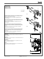
PVEO
PVEH
B
A
B
A
P A
P B
MA
P
S
V310158.A
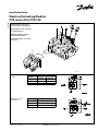
Oliestrømmens retning for
standard monterede grupper.
Oil flow direction for standard
assembled groups.
Richtung des Ölstroms für
Standard-Baugruppen.
Sens du débit pour ensembles
standard.
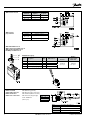
Hirschmann-version
on/off
Hirschmann-version
proportional
Function Signal voltage (U
S
)
Neutral U
S
(pin 2)
= 0.5 • U
DC
Q: P -> A U
S
(pin 2) = (0.5 -> 0.25) • U
DC
Q: P -> B U
S
(pin 2) = (0.5 -> 0.75) • U
DC
Function
Signal voltage (A or B)
A (pin 1) B (pin 2)
Neutral 0 0
Q: P -> A U
DC
0
Q: P -> B 0 U
DC

2 520L0403 • Rev CB • Mar 2014 © Danfoss A/S, 2014-03
AMP-version on/off
Function Signal voltage (US)
Neutral U
S
(pin 1)
= 0.5 • U
DC
Q: P -> A
U
S
(pin 1) = (0.5 -> 0.25) • U
DC
Q: P -> B U
S
(pin 1) = (0.5 -> 0.75) • U
DC
Function
Signal voltage (A or B)
A (pin 1) B (pin 2)
Neutral 0 0
Q: P -> A U
DC
0
Q: P -> B 0 U
DC
AMP-version
proportional
AMP-stik til PVE serie 4
AMP connector for PVE series 4
AMP-Stecker für PVE Serie 4
Kit AMP pour PVE serie 4
PVE function (grey)
Pos. Description Qty. AMP Code no.
Danfoss
Code no.
Danfoss
Code no with
4 mm cable
1 Wire sealing (blue) 4* 828904-1
157B4992
min. 5 pcs
157B4994
min. 5 pcs.
2 Blind plug (transparent) 1 828922-1
3 JPT contact (loose piece) 4* 929930-1
4 JPT housing keying B (gray) 1 2-967059-1
JPT = AMP Junior Power Timer
Kabel med stik
Cable with connector
Kabel mit Stecker
Câble avec connecteur
PVE-funktion (gråt stik)
PVE-function (grey connector)
PVE-Funktion (Grauer Stecker)
PVE-Fonction (Support gris)
Code: 157B4994
(min. 5 pcs.)
Pin 1 Hvid, White, Weiß, Blance
Pin 2 Blå, Blue, Blau, Bleu
Pin 3 Gul, Yellow, Gelb, Jaune
Pin 4 Rød, Red, Rot, Rouge
Pin 4 F
Pin 3 U-
Pin 2 U+
Pin 1 Us

© Danfoss A/S, 2014-03 520L0403 • Rev CB • Mar 2014 3
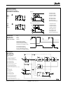
PVE Fejlovervågning
PVE fault monitoring
PVE Fehlerüberwachung
Surveillance de défauts PVE
A: Eksternt relæ
A: External relay
A: Externes Relais
A: Relais externe
B: Magnetventil
B: Solenoid valve
B: Magnetventil
B: Electrodistributeur
A: Eksternt relæ
A: External relay
A: Externes Relais
A: Relais externe
B: Magnetventil
B: Solenoid valve
B: Magnetventil
B: Electrodistributeur
Normal
Fejl/Fault/Fehler/Défaut
Grøn
Green
Grün
Vert
Rød
Red
Rot
Rouge
Reaktionstid
Reaction time
Reaktionszeit
Temp de réaction
Blokdiagram
Block diagram
Blockdiagramm
Stéreogramme
Active
(a) : Afbrydelse af magnetventiler
(a) : Cutoff of solenoid valves
(a) : Abschalten der Magnetventile
(a) : Coupure des electrodistributeurs
(b) : Styresignal til LED
(b) : Control signal for LED
(b) : Steuersignal für LED
(b) : Signal de commande pour LED
(c) : Styresignal til alarmudgang
(c) : Control signal for alarm output
(c) : Steuersignal für Alarmausgang
(c) : Signal de commande pour la sortie d'alarme
Passiv
(a) : forefindes ikke
(a) : does not exist
(a) : nicht vorhanden
(a) : n'existe pas
(b) : Styresignal til LED
(b) : Control signal for LED
(b) : Steuersignal für LED
(b) : Signal de commande pour LED
(c) : Styresignal til alarmudgang
(c) : Control signal for alarm output
(c) : Steuersignal für Alarmausgang
(c) : Signal de commande pour la sortie d'alarme
Fejl
Fault
Fehler
Défaut
Aktiv fejlovervågning
Active fault monitoring
Aktive Fehlerüberwachung
Surveillance de défauts active
Passiv fejlovervågning
Passiv fault monitoring
Passive Fehlerüberwachung
Surveillance de défauts passive

4 520L0403 • Rev CB • Mar 2014 © Danfoss A/S, 2014-03
P
MA
LS
max. 2[0.08]
A
max. 2[0.08]
B
V310104.A
PVEH
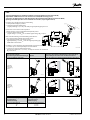
Justering af PVE når max. håndtagsvandring overskrides (PVE er forjusteret fra fabrik)
Adjustment of PVE when max. lever travel is exceeded (PVE is factory-preset)
Justierung der PVE wenn max. Hebelwanderung überschritten wird (PVE ist vorjustiert ab Werk)
Ajustage de la PVE quand la course maximale est excédée (est préréglé à l'usine)
Kontroller max. håndtagsvandring i neutralstilling
1. Sæt hydraulisk tryk på systemet
2. Tilslut forsyningsspænding (U
DC
)
(Signalspænding = 0,5 × U
DC
), eller afbryd signalspænding (U
S
) på ben 2.
Check max. lever travel in neutral position
1. Make sure the system is supplied with hydraulic power
2. Connect supply voltage (U
DC
)
(Signal voltage = 0,5 × U
DC
), or cut off the signal voltage (U
S
) on pin 2.
Max. Hebelwanderung in Neutralstellung kontrollieren:
1. Das System unter hydraulischen Druck setzen
2. Versorgungsspannung anschliessen (U
DC
)
(Signalspannung = 0,5 × U
DC
), oder die Signalspannung (U
S
)
auf Klemme 2 abschalten.
Contrôler la course maximale du manipulateur en position neutre
1. S'assurer que le circuit hydraulique est fourni d'huile.
2. Connecter la tension d'alimentation (U
DC
)
(Tension de commande = 0,5 × U
DC
), ou couper la tension de commande
(U
S
) sur borne 2.
Overskridelse
Lever travel exceeded in
Überschreitung der Hebelwanderung in
La course maximale estexcédée
PVG 120
Omdrejningsretning for justering af positionstransducer
Direction of rotation for adjustment of position transducer
Drehrichtung beim Justieren des Positionstransducers
Sens de rotation pour l'ajustage du transducteur de position
A - retning
Direction A
A - Richtung
Sense A
A
V310177.A
B - retning
Direction B
B - Richtung
Sense B
V310108.A
B
Transducer omdrejning
Turn of transducer
Transducerdrehung
Rotation du transducteur
Håndtagsbevægelse
Movement of lever
Hebelbewegung
Mouvement du manipulateur
1/4
1/2
3/4
1.5 mm
3.0 mm
4.5 mm

© Danfoss A/S, 2014-03 520L0403 • Rev CB • Mar 2014 5
Montage af PVE
Installation of PVE
Montage von PVE
Installation de PVE
Udluftning
(hvis gruppen er monteret vertikalt, anbefales det at udlufte ved
juster skruerne)
Bleeding
(if the group is installed vertically, it is recommended to bleed it at
the adjusting screws)
Entlüftung
(wenn die Gruppe vertikal montiert ist, empfehlen wir an den
Justierschrauben zu entlüften)
Purge
(si l'ensemble est monté verticalement, il est recommendé de le
purger au moyen des vis d'ajustage)
0.8 ± 0.05 daNm
(70 ± 4.5 lbf•in)
(70 ± 4.5 in-lbs
Af sikkerhedsmæssige grunde må en evt. udskiftning af O-ringe
mellem ventilblok 1 og mellemplade 2 kun foretages i en af
Danfoss’ autoriserede Service Shops.
En forveksling af PVE serie 2 til PVG 120 og PVG 32 kan føre
til selvudstyring
For security reasons, any replacement of O-rings between valve
block 1 and intermediate plate 2 may only be effected at service
shops authorized by Danfoss.
Mixing up PVE series 2 for PVG 120 and PVG 32 may lead to
self-actuation.
Aus Sicherheitsgründen darf eventuelle Auswechslung von
O-Ringen zwischen im Ventilblock 1 und Zwischenplatte 2 nur
bei Danfoss autorisierten Kunden-dienstwerkstätten ausgeführt
werden.
Eine Verwechslung der PVE Serie 2 für PVG 120 und PVG 32
mag Selbstaussteuerung ergeben.
Pour des raisons de sécurité un replacement éventuel des joints
toriques entre block de sécurité 1 et plaque intermédiaire 2 ne
devra être effectué que dans les ateliers de dépannage agréés
par Danfoss.
Une confusion de PVE série 2 pour PVG 120 et PVG 32 peut
provoquer un déplacement spontané.
PVEH
PVEO
*
190[7.48]
*
100[3.94]
T
LX
PP
V310105.A

6 520L0403 • Rev CB • Mar 2014 © Danfoss A/S, 2014-03
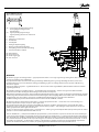
6
U
DC
= Forsyningsspænding/Supply voltage
Versorgungsspannung/Tension
d'alimentation
U
S
= Signalspænding/Signal voltage
Signalspannung/Tension de commande
E: Nødstop
E: Emergency circuit braker
E: Notschalter
E: Interrupteur
F: Udtag fra fejlovervågning
F: Branch circuit for fault indication
F: Anzapfung von der Fehlerüberwachung
F: Prise du surveillance défaut
NC: Ikke tilsluttet
NC: Not connected
NC: Nicht eingeloggt
NC: Pas connecté
25 pin SUB-D connector
(MIL-C-24308 /DIN 41652)
Push/Dir.sw.4B
Push/Dir.sw.4A
Push/Dir.sw.3B
Push/Dir.sw.3A
PVEM
PVEH/A/S
DC
V310116.A
P4B
1
PVEO
3
2
1
3
1
2
3
1
2
2
3
S2
UU
S1
P3BP3A P4A
Prop 2
Function
Prop 1
E
U
-
+
U+
+
-
DC
Neut.sw.
U
+
+
U
-
U
U- (GND)
19
Pin no.
7
8
6
3, 15, 16
1, 2, 14
10
21
20
22
F
NC
NC
WWARNING
Alle mærker og typer af retningsventiler – også proportional ventiler – kan svigte og forårsage alvorlig skade. Det er derfor vigtigt
at analysere maskinen i alle enkeltheder.
Da proportionalventiler anvendes under mange forskellige driftsbetingelser og i mange forskellige maskiner, er det alene
maskinproducentens ansvar at træffe det endelige produktvalg og sikre at samtlige maskinens krav til ydelse, sikkerhed og
advarsler er opfyldt.
Ved valg af reguleringssystem – og sikkerhedsniveau – kan man f.eks. støtte sig til EN954-1 (sikkerhedsrelaterede bestanddele i
reguleringssystemet.)
Alle Fabrikate und Typen von Wegeventilen – einschließlich Proportionalventile – können versagen und schlimme Unfälle
verursachen. Es ist daher wichtig, die Anwendung in allen Details zu analysieren.
Weil Proportionalventile unter vielen unterschiedlichen Arbeitsbedingungen und in vielen verschiedenen Anwendungen benutzt
werden, trägt allein der Maschinenhersteller die Verantwortung für seine endgültige Wahl von Produkt, und er ist ebenfalls dafür
verantwortlich, dass alle Leistungs-, Sicherheits- und Warnungsanforderungen an seine Maschine erfüllt sind.
Zur Wahl vom Reglersystem und Sicherheitsniveau kann man sich z.B. auf EN954-1 stützen.
All marks and all types of directional control valves – inclusive proportional valves – can fail and cause serious damage. It is
therefore important to analyse all aspects of the application.
Because the proportional valves are used in many different operation conditions and applications, the manufacturer of the
application is alone responsible for making the final selection of the products – and assuring that all performance, safety and
warning requirements of the application are met.
The process of choosing the control system – and safety level – could e.g. be governed by EN 954-1 (Safety related parts of control
system). See also Technical information for PVE series 4.
Tous les distributeurs - y compris les distributeurs proportionnels - peuvent tomber en panne et entraîner de sérieux dommages.
C’est la raison pour laquelle il est important d’analyser chaque aspect de l’application. Les vannes proportionnelles étant utilisées
dans de nombreuses conditions d’exploitation et applications différentes, le fabricant de l’application porte l’entière responsabilité
de la sélection finale des produits et du respect des exigences en matière de rendement, de sécurité et d’avertissement. Le choix
du système de commande – et du niveau de sécurité – peut être fait par exemple sur la base de la norme EN 954-1 (parties du
système de commande relatives à la sécurité). Se reporter également à Information technique pour PVE série 4.
-
 1
1
-
 2
2
-
 3
3
-
 4
4
-
 5
5
-
 6
6


dans d''autres langues
Documents connexes
-
Danfoss PVG 120 Guide d'installation
-
Danfoss PVG 16 Guide d'installation
-
Danfoss PVG 100 Guide d'installation
-
-
Danfoss PVHC Mode d'emploi
-
-
-
-
-