Kichler Lighting 45771PN Manuel utilisateur
- Taper
- Manuel utilisateur

Date Issued: 03/24/16 IS-45771-CB
INSTRUCTIONS
For Assembling and Installing Fixtures in Canada
Pour L’assemblage et L’installation Au Canada
We’re here to help 866-558-5706
Hrs: M-F 9am to 5pm EST
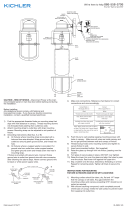
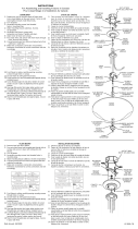
FRONT VIEW
VUE DE FACE
SOCKET HOUSING
BOÎTIER DE DOUILLE
SUPPORT KNOB
BOUTON
DE SOUTIEN
CANOPY
COUVERCLE
MOUNTING STRAP
ÉTRIER DE MONTAGE
MOUNTING SCREW
VIS DE MONTAGE
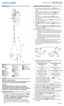
SIDE VIEW
VISTA LATERAL
WIRE NUTS
TUERCAS
DE MARIPOSA
TOP TRIM
GARNITURE
SUPÉRIEURE
ARM SUPPORT
APPUI DE BRAS
LOCK-UP KNOBS
PERILLAS
DE SUJECIÓN
LOCKWASHER
RONDELLE
DE BLOCAGE
STRAP
MOUNTING
SCREW
TORNILLO DE
MONTAJE DE
LA ABRAZADERA
GLASS
VIDRIO
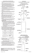
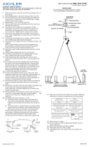
1) TURN OFF POWER.
IMPORTANT: Before you start, NEVER attempt any work
without shutting off the electricity until the work is done.
a) Go to the main fuse, or circuit breaker, box in your
home. Place the main power switch in the “OFF”
position.
b) Unscrew the fuse(s), or switch “OFF” the circuit breaker
switch(s), that control the power to the fixture or room
that you are working on.
c) Place the wall switch in the “OFF” position. If the
fixture to be replaced has a switch or pull chain, place
those in the “OFF” position.
2) Find the appropriate threaded holes on mounting strap.
Assemble mounting screws into threaded holes.
3) Attach mounting strap to outlet box. (Screws not provided).
Mounting strap can be adjusted to suit position of fixture.
4) Make wire connections. Reference chart below for correct
connections and wire accordingly.
5) Push fixture into wall, carefully passing mounting screws
through the holes.
6) Screw the lock-up knobs onto mounting screws. Tighten to
secure fixture to the wall.
7) Align a support arm through a hole on the top trim and
through a hole in the socket housing. Secure into place by
screwing in a support knob at the top of socket housing.
8) Repeat step 8 for remaining support arms.
9) Insert recommended bulb.
10) Set glass onto foam pad of bottom trim.
11) Align bottom of support arms through bottom trim holes.
(Passing the glass past bulb, through top trim ring, and
resting with the top of the glass inside socket housing).
12) While holding in place, secure by screwing in remaining
support knobs through the bottom trim to the arm sup-
ports.
13) Repeat steps 8-13 to mount the remaining glass.
Connect Black or
Red Supply Wire to:
Connect
White Supply Wire to:
Black White
*Parallel cord (round & smooth)
*Parallel cord (square & ridged)
Clear, Brown, Gold or Black
without tracer
Clear, Brown, Gold or Black
with tracer
Insulated wire (other than green)
with copper conductor
Insulated wire (other than green)
with silver conductor
*Note: When parallel wires (SPT I & SPT II)
are used. The neutral wire is square shaped
or ridged and the other wire will be round in
shape or smooth (see illus.)
Neutral Wire
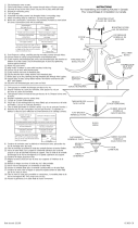
1) COUPER LE COURANT.
IMPORTANT: TOUJOURS couper l’électricité avant de
commencer le travail.
a) Localiser le coffret à fusibles ou le disjoncteur du
domicile. Mettre l’interrupteur principal en position
d’Arrêt.
b) Dévisser le ou les fusibles (ou mettre le disjoncteur
sur Arrêt) qui contrôlent l’alimentation vers le lumi
naire ou la pièce dans laquelle le travail est effectué.
c) Mettre l’interrupteur mural en position d’Arrêt. Si le
luminaire à remplacer est doté d’un interrupteur ou
d’une chaîne connectée à l‘interrupteur, placer ces
éléments en position d’Arrêt.
2) Trouver les trous letés appropriés sur le support de
montage. Visser les vis de montage dans les trous
taraudés.
3) Fixer le support de montage sur la boîte à prises. (Vis non
fournies). Le support de montage peut être réglé a n de
positionner correctement le luminaire.
4) Connecter les ls. Se porter au tableau ci-dessous pour faire
les connexions.
5) Pousser le luminaire dans le mur, en passant soigneusement
les vis de montage par les trous.
6) Visser les boules de blocage sur les vis de fixation. Serrer
pour fixer le luminaire au mur.
7) Aligner un bras de support à travers un trou sur la garniture
supérieure et à travers un trou dans le boîtier de la douille.
Fixer en serrant une boule de support à la partie supérieure
du boîtier de la douille.
8) Répéter l’étape 8 pour les autres bras.
9) Introduire l’ampoule recommandée.
10) Placer le verre sur la mousse de la garniture inférieure.
11) Aligner la partie inférieure des bras de support à travers les
trous dans la garniture inférieure. (En passant le verre au
delà de l’ampoule, par l’anneau de la garniture supérieure et
logée avec le haut du verre dans le boîtier de la douille).
12) Tout en maintenant l’ensemble en place, sécuriser en vis-
sant les autres boules de support à travers la garniture
inférieure aux supports de bras.
13) Répéter les étapes de 8 à 13 pour monter le verre restant.
Connecter le fil noir ou
rouge de la boite
Connecter le fil blanc de la boîte
A Noir A Blanc
*Au cordon parallèle (rond et lisse)
*Au cordon parallele (à angles droits el strié)
Au bransparent, doré, marron, ou
noir sans fil distinctif
Au transparent, doré, marron, ou
noir avec un til distinctif
Fil isolé (sauf fil vert) avec
conducteur en cuivre
Fil isolé (sauf fil vert) avec
conducteur en argent
*Remarque: Avec emploi d’un fil paralléle
(SPT I et SPT II). Le fil neutre est á angles
droits ou strié et l’autre fil doit étre rond ou
lisse (Voir le schéma).
Fil Neutre
-
 1
1

Kichler Lighting 45771PN Manuel utilisateur
- Taper
- Manuel utilisateur
dans d''autres langues
- English: Kichler Lighting 45771PN User manual
Documents connexes
-
 Kichler Lighting 45770PN Manuel utilisateur
-
 Kichler Lighting 49857BKT Manuel utilisateur
-
 Kichler Lighting 44286WWW Manuel utilisateur
-
 Kichler Lighting 44098CLP Manuel utilisateur
-
 Kichler Lighting 42565BK Manuel utilisateur
-
 Kichler Lighting 3623NI Manuel utilisateur
-
 Kichler Lighting 3502NI Manuel utilisateur
-
 Kichler Lighting 2347NI Manuel utilisateur
-
 Kichler Lighting 3797CH Manuel utilisateur
-
 Kichler Lighting 43754AUB Manuel utilisateur


