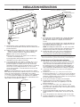
Jenn-Air JVD0303GS0 Guide d'installation
- Taper
- Guide d'installation

INSTALLATION INSTRUCTIONS FOR
DOWNDRAFT VENT
Table of Contents
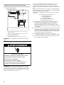
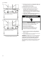
COOKTOP SAFETY
You can be killed or seriously injured if you don't immediately
You
can be killed or seriously injured if you don't
follow
All safety messages will tell you what the potential hazard is, tell you how to reduce the chance of injury, and tell you what can
happen if the instructions are not followed.
Your safety and the safety of others are very important.
We have provided many important safety messages in this manual and on your appliance. Always read and obey all safety
messages.
This is the safety alert symbol.
This symbol alerts you to potential hazards that can kill or hurt you and others.
All safety messages will follow the safety alert symbol and either the word “DANGER” or “WARNING.”
These words mean:
follow instructions.
instructions.
DANGER
WARNING
IMPORTANT:
Save for local electrical inspector’s use.
W11170792D
COOKTOP SAFETY ........................................................................ 1
INSTALLATION REQUIREMENTS .................................................3
Tools and Parts ............................................................................. 3
Location Requirements ................................................................3
Electrical Requirements ...............................................................4
Venting Requirements ................................................................10
External Venting Dimensional Planning .....................................11
INSTALLATION INSTRUCTIONS .................................................13
Mounting Bracket Installation ....................................................13
Install Foam Strips .....................................................................13
Recirculation (Non-Ducted) Installation .....................................13
Install Cooktop, Downdraft Vent, and
Blower Motor Assembly .............................................................14
Complete Installation .................................................................15
WIRE DIAGRAM ...........................................................................17
INSTRUCTIONS D’INSTALLATION POUR LE
SYSTÈME D’EXTRACTION PAR LE BAS
SÉCURITÉ DE LA TABLE DE CUISSON .....................................19
EXIGENCES D’INSTALLATION ...................................................21
Outils et pièces ...........................................................................21
Exigences d’emplacement .........................................................21
Spécications électriques ..........................................................22
Exigences concernant l’évacuation ...........................................28
Planication dimensionnelle de ventilation externe ...................29
INSTRUCTIONS D’INSTALLATION .............................................31
Installation du support de xation .............................................31
Installation des bandes de mousse ...........................................31
Installation avec recyclage (sansconduit) .................................31
Installation de la table de cuisson, du système d’extraction
par le bas et du moteur du ventilateur .......................................32
Terminer l’installation .................................................................. 33
SCHÉMA DE CÂBLAGE ...............................................................35
Table des matières
IMPORTANT:
Conserver ces instructions à l’usage de l’inspecteur des
installations électriques local.

2
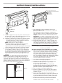
IMPORTANT SAFETY INSTRUCTIONS
READ AND SAVE THESE INSTRUCTIONS

3
INSTALLATION REQUIREMENTS
Tools and Parts
Gather the required tools and parts before starting installation.
Read and follow the instructions provided with any tools
listed here.
Tools Needed
■ Tape measure ■ Marker or pencil
■ Phillips screwdriver ■ Pliers
■ Flat-blade screwdriver ■ Jigsaw
■ Level ■ Caulking
■ Drill ■ Aluminum metal duct tape
Parts Supplied
Check that all parts are included.
■ Blower housing assembly with electrical box and intake
assembly
■ Grease lter
■ 2 - Type-A brackets
■ 4 - Type-B brackets
■ 7 - Thread cutting screws
■ Round duct 2-piece telescoping ducts
■ 1 - Blower assembly duct mounting ring
■ Foam strip
■ 1 - Intake Transition
Parts Needed
For vented installations:
■ 6" (15.2 cm) round metal ducting.
■ Jenn-Air
®
wall cap:
Jenn-Air
®
6" (15.2 cm) round wall cap with damper
■ (8) Round or pan head wood and (8) sheet metal screws
See the “Assistance or Service” section in your Use and Care
manual to order.
For non-vented installations:
■ Recirculation Kit part number W10807915 (See the
“Assistance or Service” section in your Use and Care
manualto order).
a. Recirculation duct housing
b. (4) Mounting screws
c. (2) Charcoal lters
d. Recirculation housing cover
e. (2) Mounting screws – cover
f. Duct extension
g. (4) Mounting screws – duct extension
For non-vented installations (recirculation only):
■ 1-6" (15.2 cm) round 90 degree elbow and 1-6" (15.2 cm)
round to 3Z\v" x 10" (8.3 cm x 25.4 cm) transition and
1- 3Z\v" x 10" (8.3 cm x 25.4 cm) elbow.
■ Plywood Pedestal to raise blower mounting. See “Product
Dimensions” section for detail non-vented installation.
■ For side cabinet discharge a 3¼” x 10” (8.3 cm x 25.4 cm)
straight duct will also be required.
Check local codes. Check existing electrical supply. See the
“Electrical Requirements” section.
It is recommended that all electrical connections be made by
a licensed, qualied electrical installer.
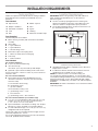
Location Requirements
IMPORTANT: Observe all governing codes and ordinances.
When installing the downdraft vent, use the minimum
dimensions given.
■ Use the countertop opening dimensions that are given
with these Installation Instructions. Given dimensions are
minimum clearances and provide 0" (0 cm) clearance.
■ The model/serial/rating label is located on the front face of
the electrical junction box cover.
■ Grounded electrical supply is required. See the “Electrical
Requirements” section.
■ If cabinet has drawers, drawers will need to be removed
and drawer fronts installed on front of cabinet.
NOTE: The exhaust system is for outside venting. For
non-vented (recirculating) installation, see “Recirculation: Non-
vented (Recirculating) Installations Only” in the “External Venting
Dimensional Planning” section. Recirculating Kit part number
W10807915 is available from your dealer or an authorized parts
distributor.
IMPORTANT: An under-counter built-in oven cannot be installed
under this product.
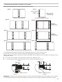
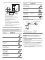
A
A. Model/serial/rating label location

4
This downdraft vent is equipped with an electronic touch pad
system that will not operate if plugged into an outlet that is not
properly polarized. Do not use GFCI circuit.
If codes permit and a separate ground wire is used, it is
recommended that a qualied electrical installer determine that
the ground path is adequate.
A copy of the above code standards can be obtained from:
National Fire Protection Association
1 Batterymarch Park
Quincy, MA 02169-7471
CSA International
8501 East Pleasant Valley Road
Cleveland, OH 44131-5575
■ A 120 volt, 60 Hz., AC only, 15 amp fused, electrical circuit
is required. A time-delay fuse or circuit breaker is also
recommended. It is recommended that a separate circuit
serving only this downdraft vent be provided.
■ Electronic touch pad systems operate within wide voltage
limits, but proper grounding and polarity are necessary.
Check that the outlet provides 120 volt power and is
correctly grounded and polarized.
■ The wiring diagram is provided with this downdraft vent. See
the “Wiring Diagram” section.
■ Downdraft vent must have a dedicated electrical receptacle
and power supply.
Electrical Connection Locations
A. 3 prong grounding type outlet with correct polarity
B. 6" (15.2 cm) from centerline of downdraft vent intake
C. 18" (45.7 cm) minimum
D. 30" (76.2 cm) power cord (supplied)
C
A
D
B
Center of Downdraft
Vent Intake
NOTE: Cooktop conguration may differ.
Electrical Requirements
IMPORTANT: The downdraft vent must be electrically grounded
in accordance with local codes and ordinances, or in the
absence of local codes, with the National Electrical Code, ANSI/
NFPA 70 or Canadian Electrical Code, CSA C22.1.
Electrical Shock Hazard
Plug into a grounded 3 prong outlet.
Do not remove ground prong.
Do not use an adapter.
Do not use an extension cord.
Failure to follow these instructions can result in death,
fire, or electrical shock.
WARNING

5
Planning Your Cabinet and Cooktop Cutouts
Installation Options for Modular Downdraft Vent
The downdraft vent can be mounted between cooktops or on the sides of them.
If mounted on the right side, this requires relief cuts (back cutting) on the countertop.
Planning your counter cutout, refer to installation instruction for modular cooktops and full size cooktops and add:
■ 3
7
\
8
" (9.8 cm) for each downdraft vent mounted between cooktops
■ 3
51
\
64
" (9.6 cm) for each downdraft vent mounted on outside of cooktops
NOTE: When downdraft vent is mounted on outside of cooktop on right hand side, against the countertop, the countertop must be cut
as shown in Option A or Option B. The shaded areas of the gures represent the countertop.
15" (38.1 cm)
(DD on outside of cooktop)(DD between cooktops)
DD 15" (38.1 cm) 15" (38.1 cm) DD
15" (38.1 cm) DD15" (38.1 cm) 15" (38.1 cm) DD DD DD
DD DD
30" (76.2 cm) OR 36" (91.4 cm)
DD DD
DDDD DD DD
Downdraft
Vent
(DD)
15" (38.1 cm) cooktop
(15" [38.1 cm])
15" (38.1 cm) 15" (38.1 cm)
15" (38.1 cm)
15" (38.1 cm)
15" (38.1 cm)
15" (38.1 cm)
15" (38.1 cm)
15" (38.1 cm)
15" (38.1 cm)
30" (76.2 cm) OR 36" (91.4 cm)30" (76.2 cm) OR 36" (91.4 cm)
1
15 minOFF
2
1
15 minOFF
2
1
15 minOFF
2 1
15 minOFF
21
15 minOFF
2
1
15 minOFF
2
1
15 minOFF
2
1
15 minOFF
2
1
15 minOFF
2 1
15 minOFF
2
1
15 minOFF
2
1
15 minOFF
2
1
15 minOFF
2
1
15 minOFF
2
Require countertop
relief cuts
Require countertop
relief cuts
Option 1
Option 5
Option 6
Option 7
Option 8
Option 2
Option 3
Option 4
[2.2 cm]
Downdraft
Downdraft
7
8
"
Counter Top
Counter Top
[3.18 cm]
1
1
4
"
[3.2 cm]
1
1
4
"
[2.2 cm]
7
8
"
[3.18 cm]
1
1
4
"
115
0
Option A Option B
Countertop Relief Cut Options

6
Overall Width Options
Options Width Total
Option 1
15" (38.1 cm) + 3
7
/
8
" (9.8 cm) +
15" (38.1 cm)
33
7
/
8
" (86.0 cm)
Option 2
15" (38.1 cm) + 3
7
/
8
" (9.8 cm) +
15" (38.1 cm) + 3
7
/
8
" (9.8 cm) +
15" (38.1 cm)
52
23
/
32
" (133.9
cm)
Option 3
15" (38.1 cm) + 3
7
/
8
" (9.8 cm) +
15" (38.1 cm) + 15" (38.1 cm) +
3
7
/
8
" (9.8 cm) + 15" (38.1 cm)
67
23
/
32
" (172 cm)
Option 4
15" (38.1 cm) + 3
7
/
8
" (9.8 cm) +
30" (76.2 cm) / 36" (91.4 cm) +
3
7
/
8
" (9.8 cm) + 15" (38.1 cm)
67
23
/
32
" (172 cm)
/ 73
45
/
64
" (187.2
cm)
Option 5
3
7
/
8
" (9.8 cm) + 15" (38.1 cm) 18
7
/
8
" (47.9 cm)
Option 6
3
7
/
8
" (9.8 cm) + 15" (38.1 cm) +
15" (38.1 cm) + 3
7
/
8
" (9.8 cm)
37
23
/
32
" (95.8 cm)
Option 7
3
7
/
8
" (9.8 cm) + 30" (76.2 cm) /
36" (91.4 cm) + 3
7
/
8
" (9.8 cm)
37
23
/
32
" (95.8 cm)
/ 43
45
/
64
" (111
cm)
Option 8
3
7
/
8
" (9.8 cm) + 30" (76.2 cm) /
36" (91.4 cm) + 3
7
/
8
" (9.8 cm) +
15" (38.1 cm)
52
23
/
32
" (133.9
cm) / 58
15
/
64
"
(149.1 cm)
NOTE: All cutout depths are 20
3
/
8
" (51.7 cm).
Cooktop cutout dimensions are provided here for reference only.
Refer to the cooktop installation instructions for complete
cooktop installation information.
Multi-Unit Dimensions
Units Overall Width
Cutout
Width
One 15" (38.1 cm) unit 15"
(38.1 cm)
14
3
/
8
"
(36.5cm)
Two 15" (38.1 cm) units 30"
(76.2 cm)
29
3
/
8
"
(74.6cm)
Three 15" (38.1 cm) units 45"
(114.3 cm)
44
7
/
16
"
(112.9 cm)
Four 15" (38.1 cm) units 60"
(152.4 cm)
59
7
/
16
"
(151.0 cm)
30" (76.2 cm) cooktop and
one 15" (38.1 cm) unit
45"
(114.3 cm)
44
3
/
8
"
(112.7 cm)
30" (76.2 cm) cooktop and
two 15" (38.1 cm) units
60"
(152.4 cm)
59
7
/
16
"
(151.0 cm)
36" (91.4 cm) cooktop and
one 15" (38.1 cm) unit
51"
(129.5 cm)
50
3
/
8
"
(128.0 cm)
NOTE: After making the countertop cutout, some installations
may require notching down the base cabinet side walls to clear
the burner box. To avoid this modication, use a base cabinet
with sidewalls wider than the cutout.
If cabinet has a drawer, a 4" (10.2 cm) depth clearance from the
countertop to the top of the drawer (or other obstruction) in base
cabinet is required. The drawer depth may need to be shortened
to avoid interfering with the regulator and power cord.
Flush Installation Dimensions
All cooktops can be mounted with a frameless standard
installation sitting on top of the countertop surface or ush
with the top of the countertop. If the cooktop is to be mounted
ush with the countertop, a 11/64" (4.3 mm)-deep recessed
area surrounding the cooktop cutout must be provided with the
following dimensions.
NOTE: This option is not recommended for countertops with a
molded backsplash. Do not silicone seal in place.
Multi-Unit Flush Dimensions
Units
Recessed
Area Width (D)
Cutout
Width (C)
One 15" (38.1 cm) unit 15
1
/
8
"
(38.4cm)
14
3
/
8
"
(36.5cm)
Two 15" (38.1 cm) units 30
1
/
8
"
(76.5cm)
29
3
/
8
"
(74.6cm)
Three 15" (38.1 cm) units 45
1
/
8
"
(114.6cm)
44
7
/
16
"
(112.9 cm)
Four 15" (38.1 cm) units 60
1
/
8
"
(152.7cm)
59
7
/
16
"
(151.0 cm)
30" (76.2 cm) cooktop and
one 15" (38.1 cm) unit
45
1
/
8
"
(114.6cm)
44
3
/
8
"
(112.7 cm)
30" (76.2 cm) cooktop and
two 15" (38.1 cm) units
60
1
/
8
"
(152.7cm)
59
7
/
16
"
(151.0 cm)
36" (91.4 cm) cooktop and
one 15" (38.1 cm) unit
51
1
/
8
"
(129.9cm)
50
3
/
8
"
(128.0 cm)
IMPORTANT: If multiple units are installed side by side, the
mounting bridge kit W11031680 is needed for proper installation.
D
Width
C
A
Depth
B
E
F
E
Cooktop
Foam Strip
A. Recessed area depth - 21
3
/
16
" (53.8 cm)
B. Cutout depth - 20
3
/
8
" (51.8 cm)
C. See the Multi-Unit Flush Dimensions table.
D. See the Multi-Unit Flush Dimensions table.
E. Recessed area depth 11/64" (4.3 mm)
F. Recessed area radius 5/64" (2.0 mm) maximum

7
Recessed Area Width/Cutout Width Mounting Bridge Installation with Downdraft
Note: When cooktop is located on left side of downdraft intake,
the bridge must be installed in a reversed position vs that
described in the Bridge Kit Installation Instruction. After securing
the bridge, the cooktop can be removed for easier access to the
horizontal mounting tab on bridge.
A. 3
7
/
8
" (9.8 cm)
B. 21" (53.3 cm)
C. 7/64" (2.9 mm) radius (4-corner radius)
D. 8
7
/
8
" (22.5 cm)
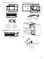
Product Dimensions
Vent
C
A
B
D

8
Blower Housing Assembly
Front Side
A
B
C
D
E
F
G
H
I
J
K
M
L
A. 6
3
/
8
" (16.2 cm)
B. 1
1
/
2
" (3.8 cm)
C. 1
15
/
16
" (4.9 cm)
D. Ø
1
/
8
" (3 mm)
E. 8
7
/
8
" (22.5 cm)
F. 19" (48.3 cm)
G. 3
1
/
32
" (7.7 cm)
H. Downdraft Vent
Centerline
I. 1
1
/
8
" (2.9 cm)
J. 11" (27.9 cm)
K. 4" (10.2 cm)
L. 15
9
/
32
" (38.8 cm)
M. 13
7
/
16
" (33.4 cm)
N. 21" (53.3 cm)
O 20
5
/
16
" (51.6 cm)
P. 8
7
/
8
" (22.5 cm)
Q. 1
15
/
32
" (3.7 cm)
R. 9" (22.9 cm)
S. 3
15
/
32
" (8.8 cm)
T. 3
17
/
32
" (9.0 cm)
U. 1
1
/
2
" (3.2 cm)
V. 4" (10.2 cm)
W. 5
1
/
2
" (14.0 cm)
X. 13/32" (1.0 cm)
Right Side
N
O
X
P
Q
R
S
T
W
V
U

9
Recirculation Assembly (Accessory)
A. 18
3
/
8
" (46.6 cm)
B. 3
3
/
4
" (9.5 cm)
C. 5
3
/
4
" (14.7 cm)
D. 6
3
/
4
" (17.1 cm)
E. 9/16" (14 mm)
F. 9/16" (14 mm)
G. 9
7
/
8
" (25.0 cm)
H. 17
5
/
8
" (44.8 cm)
J. 3
3
/
32
" (7.8 cm)
K. 2" (5.0 cm)
L. 3/16" (4.8 mm) diameter (4)
M. 5/16" (7.9 mm)
N. 17" (43.2 cm)
C
E
GF
N
D
A
H
A
L
K
B
J
M
Recirculation Cover (Part of Recirculation Kit)
A. 18
1
/
2
" (47.0 cm)
B. 3
31
/
32
" (10.1 cm)
C. 11/16" (1.7 cm)
A
B
C
Center Line
of Downdraft Vent
Intake
Plan View
of Cutouts
Front of Cabinet
Kick Plate
A
B
C
D
E
F
G
H
Pedestal
Center line
of Downdraft Vent
Intake
Blower Mounting
Bracket (Type - B)
Secure to Cabinet
A. 19" (48.3 cm)
B. 5
3
/
4
" (14.6 cm)
C. 7" (17.8 cm)
D. 15/16" (2.4 cm)
E. 17
1
/
8
" (43.5 cm)
F. 13
1
/
8
" (33.3 cm)
G. 2
1
/
2
" (6.4 cm)
H. 24
3
/
64
" (61.1 cm)
Plywood 3/4" (1.9 cm)
Reinforce all joints
C
B
A
A. 11" (27.9 cm)
B. 13" (33 cm)
C. 7
3
/
4
" (19.7 cm)
Pedestal
Internal (Non-Ducted) Venting

10
IMPORTANT: This appliance must be exhausted outdoors
unless you are using the Recirculation Accessory Kit. See the
“Accessories” section in yourUse and Care manual to order.
■ Do not terminate the vent system in an attic or other
enclosed area.
■ Vent system must terminate to the outside.
■ Use only a 3Z\v" x 10" (8.3 cm x 25.4 cm) rectangular metal
vent or 6" (15.2 cm) round metal vent. Rigid metal vent is
recommended. Do not use a plastic or metal foil vent.
■ Before making cutouts, make sure there is proper clearance
within the wall or oor for the exhaust vent.
■ Do not cut a joist or stud unless absolutely necessary.
If a joist or stud must be cut, then a supporting frame must
be constructed.
■ The size of the vent should be uniform.
■ The vent system must have a damper.
■ Use vent clamps and aluminum metal duct tape to seal all
joints in the vent system.
■ Use caulking to seal exterior wall or roof opening around
the cap.
■ Determine which venting method is best for your application.
For Best Performance:
■ Use 26-gauge minimum galvanized or 25-gauge minimum
aluminum metal vent. Poor oquality pipe ttings can reduce
airow. For external venting, a exible metal vent is not
recommended.
NOTE: Local codes may require a heavier gauge material.
■ Metal duct may be reduced to 30-gauge galvanized steel
or 26-gauge aluminized steel if allowed by local codes.
This reduction is based on information in the International
Residential Codes Section M1601.1 (2006 edition).
■ Avoid installing 2 elbows together.
■ Use no more than three 90° elbows.
■ If an elbow is used, install it as far away as possible from
the hood’s vent motor exhaust opening.
■ Make sure there is a minimum of 18" (45.7 cm) of straight
vent between the elbows if more than one elbow is used.
Elbows too close together can cause excess turbulence
that reduces airow.
■ Do not use a 5" (12.7 cm) elbow in a 6" (15.2 cm) or
3¼" x 10" (8.3 cm x 25.4 cm) system.
■ Do not reduce to a 5" (12.7 cm) system after using a
6" (15.2 cm) or 3¼" x 10" (8.3 cm x 25.4 cm) tting.
■ Avoid forming handmade crimps. Handmade crimps may
restrict airow.
■ Use a Jenn-Air
®
vent cap for proper performance. If an
alternate wall or roof cap is used, be certain the cap size
is not reduced and that it has a backdraft damper.
■ Use vent clamps and aluminum metal duct tape to seal all
joints in the vent system.
■ Use caulking to seal exterior wall or roof opening around
the cap.
The length of vent the system and number of elbows should be
kept to a minimum to provide efcient performance.
The maximum equivalent length of the vent system is 35 ft
(10.7 m). For altitudes above 4,500 ft (1272 m), reduce
recommended vent run by 20% for best performance.
Cold Weather Installations
An additional backdraft damper should be installed to minimize
backward cold air ow and a thermal break should be installed
to minimize conduction of outside temperatures as part of the
vent system. The damper should be on the cold air side of the
thermal break.
Makeup Air
Local building codes may require the use of makeup air systems
when using ventilation systems greater than the specied CFM
of air movement. The specied CFM varies from locale to locale.
Consult your HVAC professional for specic requirements
in your area.
Venting Methods
Common venting methods are shown for a counter-mounted
downdraft vent cooktop. The cooktop may be vented through
the wall or oor.
A
B
A
B
Option 1 – Roof Venting Option 2 – Wall Venting
A. 6" (15.2 cm) round ducting
transitioned to 3
1
/
4
" x 10"
(8.3 cm x 25.4 cm)
rectangular floor venting
B. Roof cap
A. 6" (15.2 cm) round ducting
B. Wall cap
Option 3 – Venting Between Floor Joist
Front view of cabinet with doors removed
B A
A. 6" (15.2 cm) round
wall venting
B. Wall cap
Venting Requirements

11
External Venting Dimensional Planning
Single Unit with 6" (15.2 cm) External Discharge
■ This conguration accommodates one or two 15" (38.1 cm)
cooktops, one on either or each side of the downdraft vent
intake.
Center Line of
Downdraft Inlet
Center Line of
Blower Discharge
A
A. 6
23
/
32
" (16.2 cm)
Option: Two Downdrafts with Single 8" (20.3 cm)
External Discharge
■ This conguration accommodates one or two 15" (38.1 cm)
cooktop(s) and a 30" (76.2 cm) or 36" (91.4 cm) cooktop.
As shown, the 30" (76.2 cm) or 36" (91.4 cm) (note: 30"
[76.2 cm] cooktop requirement shown, add 6" [15.2 cm] to
the 18
9
/
64
" [46.1 cm] dimension for a 36" [91.4 cm] cooktop)
cooktop would be installed between downdraft vent intakes
and the 15" (38.1 cm) cooktop on the left side of the larger
cooktop.
A second 15" (38.1 cm) cooktop can be installed on the right
side of the 30" (76.2 cm) or 36" (91.4 cm) cooktop.
■ For a 30" (76.2 cm) or 36" (91.4 cm) cooktop and single 15"
(38.1 cm) cooktop on the right hand side of the cooktop, the
dimensions shown are to be applied in reverse.
■ Order Y-Transition Ducting Kit: W11180669
Top View
A. 33
7
/
8
" (86 cm)
B. 34
5
/
64
" (86.5 cm)
C. 15
47
/
64
" (40 cm)
D. 18
9
/
64
" (46.1 cm)
E. 6
23
/
64
" (16.2 cm)
Center Line of
Downdraft Vent Intake
Center line of
Blower Intake
Center Line of
Cutout
Center line of
Blower Intake
Center Line of
Downdraft Vent intake
Cutout Opening
Depth
Cutout Opening
Width
45° 6" Elbow
A
B
C
F
E
D
H
G
Option: Two Downdrafts with Single 8" (20.3 cm)
External Discharge
■ This conguration accommodates three 15" (38.1 cm)
cooktops, one between the downdraft vent intakes and one
on each side of the downdraft vent intakes.
■ Order Y-Transition Ducting Kit: W11180669
Center Line
Cutout
Center Line
Blower Intake
Center Line
Downdraft Vent Intake
Center Line
Y- Ducting Transition
Center Line
Downdraft Vent Intake
Cutout Opening
Depth
Cutout Opening
Width
A
B
C
D
F. Center line of blower intake
G. Center line of Y ducting transition
H. 6" (15.2 cm) ducting to size
A. 19
5
/
64
" (48.8 cm)
B. 15
29
/
32
" (40.4 cm)
C. 6
23
/
64
" (16.2 cm)
D. Center line blower intake
NOTE: Congure blower motor assembly so that the control
panel is accessible from the front.

12
Concrete Slab Installations – Exhaust Through Wall
O
L
BA
C
M
D
J
K
G
H
N
E
F
I
A. Wall cap
B. 6" (15.2 cm) round metal vent
C. 16" (40.6 cm) maximum
D. 6" (15.2 cm) round PVC sewer pipe
E. 6" (15.2 cm) round elbow
F. 6" (15.2 cm) round duct as required
G. 6" (15.2 cm) round PVC coupling
H. Concrete slab
I. 6" (15.2 cm) round PVC sewer pipe
J. 6" (15.2 cm) round 90° PVC sewer pipe elbow
K. Tightly pack gravel or sand completely around pipe.
L. 30 ft (9.1 m) maximum
M. 6" (15.2 cm) round 90° PVC sewer pipe elbow
N. 6" (15.2 cm) round PVC coupling
O. 12" (30.5 cm) minimum
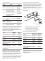
Calculating Vent System Length
To calculate the length of the system you need, add the
equivalent feet (meters) for each vent piece used in the system.
Vent Piece 6" (15.2 cm) Round
45° elbow 2.5 ft (0.8 m)
90° elbow 5.0 ft (1.5 m)
6" (15.2 cm) wall cap 0.0 ft (0.0 m)
3Z\v" x 10"
(8.3 cm x 25.4 cm)
to 6" (15.2 cm)
transition
4.5 ft (1.4 m)
6" (15.2 cm)
to 3Z\v" x 10"
(8.3 cm x 25.4 cm)
transition
1 ft (0.3 m)
3Z\v" x 10"
(8.3 cm x 25.4 cm)
to 6" (15.2 cm)
90° elbow transition
5.0 ft (1.5 m)
Vent Piece 6" (15.2 cm) Round
6" (15.2 cm)
to 3Z\v" x 10"
(8.3 cm x 25.4 cm)
90° elbow transition
5.0 ft (1.5 m)
3Z\v" x 10"
(8.3 cm x 25.4 cm)
90° elbow
5.0 ft (1.5 m)
3Z\v" x 10"
(8.3 cm x 25.4 cm)
at elbow
5.0 ft (1.5 m)
3Z\v" x 10"
(8.3 cm x 25.4 cm)
wall cap
0.0 ft (0.0 m)
Example vent system
90˚ elbow
2 ft
(0.6 m)
6 ft (1.8 m)
wall cap
1 - 90° elbow = 5 ft (1.5 m)
8 ft (2.4 m) straight = 8 ft (2.4 m)
1 - wall cap = 0 ft (0 m)
System length = 13 ft (3.9 m)
NOTE: A exible vent is not recommended. Flexible vents
create back pressure and air turbulence that greatly reduce
performance.
Recirculation: Non-Vented (Recirculating)
Installations Only
You will need to order:
■ Recirculation Kit part number W10807915 (See the
“Assistance or Service” section in your Use and Care
manualto order).
■ You may also need a section of 3Z\v" x 10" (8.3 cm x 25.4 cm)
metal duct – length required is determined by the distance
from the exhaust outlet to the back at surface of the
Recirculation Kit housing.

13
INSTALLATION INSTRUCTIONS
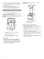
Mounting Bracket Installation
1. Mount Bracket-A to the downdraft vent body. Remove the
screws from the downdraft vent body and reassemble them to
position Bracket-A.
2. a) Mount Bracket-B to Bracket-A. Position short leg of “B”
against “A” for mounting to front or rear of cabinet. This
results in minimum extension of bracket positioning.
HINT: Pre-drive screws into Bracket-A.
b) Position the short leg of “B” against “A” for maximum
extension of bracket position.
Positioning will be determined by the nal location of the
downdraft vent in the cabinet/countertop.
3. To fasten Bracket-B to the cabinet, assemble “B” to “A” as
instructed in step 2. Secure the screws to allow “B” to be
positioned against the cabinet (front or rear). Position the
downdraft vent intake unit into the nal position in countertop.
Secure the screws holding Bracket-B to “A”. Use wood
screws (not provided) to secure Bracket-B to the front and
rear of the cabinet.
NOTE: The mounting brackets must be secured to the cabinet,
front, and rear. The front of the cabinet must have a secure wood
surface to mount the bracket to. Depending on the cabinet
construction, a wooden brace (1" x 2" [2.5 x 5.1 cm] or equivalent
1
1
/
2
" (3.8 cm) minimum width) may be required to be added to
the cabinet. Determine the planned position of downdraft vent in
cabinet and secure the brace to cabinet.
Cabinet
Downdraft Vent
Wood Brace
Bracket - B
Bracket - A
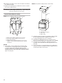
Install Foam Strips
1. If the right side of the downdraft vent is positioned against
the countertop, remove and set aside the bridge bracket
(discard after installation is complete). Do not remove
screws.
If the right side of the downdraft vent is positioned adjacent
to a cooktop, adjust the position of the bridge bracket to be
level with the top of the countertop.
NOTE: The bridge kit included with a 15" (38.1 cm) module
cannot be used on the right side of the downdraft vent. The
bridge bracket provides the required foam strip surface.
2. Install foam strips, cut to size, on the countertop (front
and rear) and left side supporting surface (bridge kit or
countertop) and on the downdraft vent bridge bracket.
Downdraft Vent Intake
Gasket (Foam Strip) Surface
Bridge Bracket
Adjusting Screw
Adjusting Direction
(Bridge Bracket)
Recirculation (Non-Ducted) Installation
Cabinet Cutouts for Non-Ducted Installations
1. After laying out the positioning of the desired cooktop and
downdraft vent units to be installed, determine the location
of the centerline of the downdraft vent intake. Mark out
the required cut out in the cabinet oor and kick plate. It is
recommended that the complete layout of downdraft vent
and cooktop(s) be established before cutting any openings.
2. Countertop and cabinet can now be cut to the prepared
requirements.
3. Install the 6" (15.2 cm) - 3
1
/
4
" x 10" (8.3 cm x 25.4 cm)
transition (stack boot) to 3
1
/
4
" x 10" (8.3 cm x 25.4 cm) elbow
to recirculating assembly. Secure all joints and seal using the
aluminum metal duct tape. This assembly can now be placed
into the opening in the cabinet oor.
4. Secure the recirculation assembly to the kick plate.
5. Install the blower to the pedestal using the 2-brackets
supplied and wood screws (not supplied) to secure the
blower to pedestal.
6. Position assembly from step 5 onto cabinet oor and
assemble 6" (15.2 cm) elbow between blower and assembly
(prepositioned in cabinet) from step 3. Secure joints and seal
with aluminum duct tape.
7. Position prepared downdraft vent intake into cabinet and
engage with blower assembly intake. Secure and seal duct
joints.
8. Secure the pedestal to the cabinet oor with wood screws.
9. Install the downdraft vent mounting brackets (see “Mounting
Bracket Installation” for more details).

14
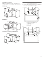
Install Cooktop, Downdraft Vent and
Blower Motor Assembly
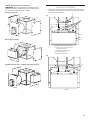
Prepare Blower Motor Assembly
NOTE: Remove shipping support from Blower Motor.
Vented
1. Secure with 3-screws and aluminum metal duct tape.
Assemble duct mounting ring to blower assembly with
3-screws. Position telescoping duct between intake
transition and blower motor (large duct to blower). Secure
ducting with sheet metal screws and use aluminum metal
tape to seal all joints.
A
C
D
B
A. Blower motor shipping support must be removed.
B. Wood block shipping support must be removed.
C. Blower Motor Housing.
D. Remove screw securing Wood Block to remove block.
Replace screw in blower housing sides after removing
wood block.
10. Install the recirculation cover to the recirculation assembly in
the cabinet kick plate.
11. Optional: The opening in the cabinet oor can be covered to
trim out the cabinet interior.
NOTE: Factory blower outlet position is rear-vented.
2. Prepare the blower assembly for installation and assemble
the two hold down brackets supplied on the blower.
3. Locate the downdraft vent in the countertop.
4. Assemble the supplied transition for connection to the
blower assembly using the four sheet metal screws supplied.
5. Assemble the telescoping duct, supplied to the blower
assembly. Secure all joints and seal using aluminum metal
duct tape.
6. Use wood screws to secure the blower to the cabinet oor
using the two blower hold down brackets supplied. Secure
one at the front and one at the rear.
A
B
D
C
A. Intake transition
B. Telescoping round duct
C. Blower ring
D. Blower motor

15
Internal (Non-Ducted) Venting and Right Discharge
Left Discharge
Rear Discharge
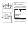
Complete Installation
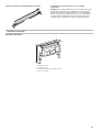
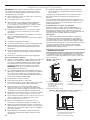
1. Connect cable assembly and ground wire from vent intake to
blower motor. See following sequence gures.
A
B
C
D
E
A. Cable assembly from vent intake
B. Remove 3 screw and put aside you
will use later
C. Tape to be removed later
D. Blower / Motor
E. Electrical box
A
A. Assemble cable
Alternate Blower Conguration
NOTE: After establishing the location of the products to be
installed, the blower can be congured to support the desired
ducting location.
A)
B)

16
2. Check that all parts are now installed. If there is an extra
part, go back through the steps to see which step was
skipped.
3. Check that you have all your tools.
4. Dispose of/recycle all packaging materials.
5. Use a mild solution of liquid household cleaner and
warm water to clean cooktop and/or vent before use. Dry
thoroughly with a soft cloth. For more information, see the
“Cooktop Care” and “Vent Care” sections of the Use and
Care manuals.
6. See the “Cooktop Use” and “Vent Use” sections of the Use
and Care manuals for operating instructions.
7. Plug into a grounded 3 prong outlet, cord is to be routed to
rear of blower and away from heat generated by cooktops.
8. Test cooktop and downdraft vent to conrm all are working.
NOTE: If the cooktop and/or vent does not work after turning
on the power, check that a circuit breaker has not tripped or
a household fuse has not blown. See the “Troubleshooting”
section of your Use and Care manual for further information.
If you need Assistance or Service:
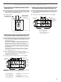
Please reference the “Warranty” section of your Use and
Caremanual.
A
A. Assemble ground wire
Electrical Shock Hazard
Plug into a grounded 3 prong outlet.
Do not remove ground prong.
Do not use an adapter.
Do not use an extension cord.
Failure to follow these instructions can result in death,
fire, or electrical shock.
WARNING
Remove tape and position connectors
into electrical box.
Using the 3 screws removed earlier,
assemble cable plate to electrical box.
C)
D)
#1 Continued

17
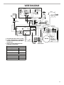
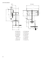
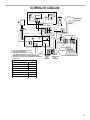
WIRE DIAGRAM
1
1
F1
RECEPTACLE 1
N
1
8
A
6
4
2
F10
HIGH
9
47
GND
1
5
1
BLUE - HIGH
BLACK
N
4
1
2
4
YELLOW - CAP
GREEN
F20
F4
N
5
F6
GREEN
22
G
RED - LOW
4
GREEN
7
3
PLUG 1
3
B
F2
WHITE
1
BROWN - LOW
LOW
BLACK
3
5
WHITE
3
5
BLUE - HIGH
9
GREY
6
F22
2
BLUE
C
F9
6
WHITE
PLUG 2
3
8
L1
3
2
RED
2
6
L1
RED - CAP
4
GREY
LOW VOLTAGE 12 V DC
BLUE
WHITE
WHITE
RED
RED
BLUE
BLACK
BLACK
BLACK
BLACK
BLACK
MOTOR
PLUG
MOTOR
RECEPTACLE
MOTOR
12V
DC
MAIN
BOARD
On
Board
E.M.C
Filter
PANEL
SWITCH
HOLD
DOOR
CLOSED
ELECTRO
MAGNET
LED
LAMP
SWITCH
LED
STRIP
12V DC
2.4 W
USER
INTER.
RECEPTACLE 2
MOTOR & CAPACITOR
PLUG RECEPTACLE
CAPACITOR
MOTOR
IN-LINE
CONNECTOR
DC
12V
.33A
POWER
SUPPLY
25
uf
WHITE
A - NO OPERATION UNTIL DOOR IS CLOSED.
B - 12V RED & WHITE OUTPUT IS ENERGIZED
HOLDING THE DOOR OPEN AND TURNS
ON LED STRIP.
C - ONCE B HAS BEEN ENERGIZED USER
INTERFACE IS NOW ACTIVE.
Power Supply 120 VAC
Frequency
60Hz
Power Absorption
310W
Current
2.6A
MOTOR RESISTANCE (Ohms)
Blue/White
15.6
Brown/White
25.5
Room Temp.
73.4
°
F (23
°
C)
MOTOR PREFORMANCE SPECIFICATIONS

18
NOTES

19
SÉCURITÉ DE LA TABLE DE CUISSON
Risque possible de décès ou de blessure grave si vous ne
suivez pas immédiatement les instructions.
Risque possible de décès ou de blessure grave si vous
ne suivez pas les instructions.
Tous les messages de sécurité vous diront quel est le danger potentiel et vous disent comment réduire le risque de blessure et
ce qui peut se produire en cas de non-respect des instructions.
Votre sécurité et celle des autres est très importante.
Nous donnons de nombreux messages de sécurité importants dans ce manuel et sur votre appareil ménager. Assurez-vous de
toujours lire tous les messages de sécurité et de vous y conformer.
AVERTISSEMENT
DANGER
Voici le symbole d’alerte de sécurité.
Ce symbole d’alerte de sécurité vous signale les dangers potentiels de décès et de blessures graves à vous
et à d’autres.
Tous les messages de sécurité suivront le symbole d’alerte de sécurité et le mot “DANGER” ou
“AVERTISSEMENT”. Ces mots signifient :

20
IMPORTANTES INSTRUCTIONS DE SÉCURITÉ
LIRE ET CONSERVER CES INSTRUCTIONS
AVERTISSEMENT : POUR RÉDUIRE LE RISQUE
D'INCENDIE, CHOC ÉLECTRIQUE OU DOMMAGES
CORPORELS, RESPECTER LES INSTRUCTIONS
SUIVANTES :
■ Utiliser cet appareil uniquement dans les applications
envisagées par le fabricant. Pour toute question, contacter
le fabricant.
■ Avant d'entreprendre un travail d'entretien ou de nettoyage,
interrompre l'alimentation de la hotte au niveau du tableau
de disjoncteurs, et verrouiller le tableau de disjoncteurs
pour empêcher tout rétablissement accidentel de
l'alimentation du circuit. Lorsqu'il n'est pas possible de
verrouiller le tableau de disjoncteurs, placer sur le tableau
de disjoncteurs une étiquette d'avertissement proéminente
interdisant le rétablissement de l'alimentation.
■ Tout travail d'installation ou câblage électrique doit être
réalisé par une personne qualifiée, dans le respect des
prescriptions de tous les codes et normes applicables, y
compris les codes du bâtiment et de protection contre les
incendies.
■ Ne pas faire fonctionner un ventilateur dont le cordon ou la
fiche est endommagé(e). Jeter le ventilateur ou le retourner
à un centre de service agréé pour examen et/ou réparation.
■ Une source d'air de débit suffisant est nécessaire pour le
fonctionnement correct de tout appareil à gaz (combustion
et évacuation des gaz à combustion par la cheminée), pour
qu'il n'y ait pas de reflux des gaz de combustion. Respecter
les directives du fabricant de l'équipement de chauffage et
les prescriptions des normes de sécurité - comme celles
publiées par la National Fire Protection Association (NFPA)
et l'American Society for Heating, Refrigeration and Air
Conditioning Engineers (ASHRAE), et les prescriptions des
autorités réglementaires locales.
■
Lors des opérations de découpage et de perçage dans un
mur ou un plafond, ne pas endommager les câblages
électriques et les canalisations qui peuvent s’y trouver.
■ Les ventilateurs d'évacuation doivent toujours décharger
l'air à l'extérieur.
MISE EN GARDE : Cet appareil est conçu uniquement
pour la ventilation générale. Ne pas l'utiliser pour l'extraction
de matières ou vapeurs dangereuses ou explosives.
MISE EN GARDE : Pour minimiser le risque d'incendie
et évacuer adéquatement les gaz, veiller à acheminer l'air
aspiré par un conduit jusqu'à l'extérieur - ne pas décharger
l'air aspiré dans un espace vide du bâtiment comme une
cavité murale, un plafond, un grenier, un vide sanitaire ou
un garage.
AVERTISSEMENT :
POUR RÉDUIRE LE RISQUE
D'INCENDIE, UTILISER UNIQUEMENT DES CONDUITS
MÉTALLIQUES.
AVERTISSEMENT : POUR MINIMISER LE RISQUE
D'UN FEU DE GRAISSE SUR LA CUISINIÈRE :
■ Ne jamais laisser un élément de surface fonctionner à
puissance de chauffage maximale sans surveillance. Un
renversement/débordement de matière graisseuse pourrait
provoquer une inflammation et la génération de fumée.
Utiliser une puissance de chauffage moyenne ou basse
pour le chauffage d'huile.
■ Veiller à toujours faire fonctionner le ventilateur de la hotte
lors de la cuisson avec une puissance de chauffage élevée
ou lors de la cuisson d'un mets à flamber (à savoir crêpes
Suzette, cerise jubilée, steak au poivre flambé).
■
Nettoyer fréquemment les ventilateurs d'extraction. Veiller à
ne pas laisser la graisse s'accumuler sur les surfaces du
ventilateur ou des filtres.
■ Utiliser toujours un ustensile de taille appropriée. Utiliser
toujours un ustensile adapté à la taille de l'élément
chauffant.
AVERTISSEMENT : POUR RÉDUIRE LE RISQUE DE
DOMMAGES CORPORELS APRÈS LE DÉCLENCHEMENT
D'UN FEU DE GRAISSE SUR LA CUISINIÈRE, APPLIQUER
LES RECOMMANDATIONS SUIVANTES :
a
■ Placer sur le récipient un couvercle bien ajusté, une tôle à
biscuits ou un plateau métallique POUR ÉTOUFFER LES
FLAMMES, puis éteindre le brûleur. VEILLER À ÉVITER
LES BRÛLURES. Si les flammes ne s'éteignent pas
immédiatement, ÉVACUER LA PIÈCE ET APPELER LES
POMPIERS.
■ NE JAMAIS PRENDRE EN MAIN UN RÉCIPIENT
ENFLAMMÉ - vous risquez de vous brûler.
■ NE PAS UTILISER D'EAU, ni un torchon humide - ceci
pourrait provoquer une explosion de vapeur brûlante.
■
Utiliser un extincteur SEULEMENT si :
– Il s'agit d'un extincteur de classe ABC, dont on connaît le
fonctionnement.
– Il s'agit d'un petit feu encore limité à l'endroit où il s'est
déclaré.
– Les pompiers ont été contactés.
– Il est possible de garder le dos orienté vers une sortie
pendant l'opération de lutte contre le feu.
a
Recommandations tirées des conseils de sécurité en cas
d'incendie de cuisine publiés par la NFPA.
■ AVERTISSEMENT : Pour réduire le risque d'incendie
ou de choc électrique, ne pas utiliser ce ventilateur avec un
quelconque dispositif de réglage de la vitesse à semi-
conducteurs.
La page est en cours de chargement...
La page est en cours de chargement...
La page est en cours de chargement...
La page est en cours de chargement...
La page est en cours de chargement...
La page est en cours de chargement...
La page est en cours de chargement...
La page est en cours de chargement...
La page est en cours de chargement...
La page est en cours de chargement...
La page est en cours de chargement...
La page est en cours de chargement...
La page est en cours de chargement...
La page est en cours de chargement...
La page est en cours de chargement...
La page est en cours de chargement...
-
 1
1
-
 2
2
-
 3
3
-
 4
4
-
 5
5
-
 6
6
-
 7
7
-
 8
8
-
 9
9
-
 10
10
-
 11
11
-
 12
12
-
 13
13
-
 14
14
-
 15
15
-
 16
16
-
 17
17
-
 18
18
-
 19
19
-
 20
20
-
 21
21
-
 22
22
-
 23
23
-
 24
24
-
 25
25
-
 26
26
-
 27
27
-
 28
28
-
 29
29
-
 30
30
-
 31
31
-
 32
32
-
 33
33
-
 34
34
-
 35
35
-
 36
36


Jenn-Air JVD0303GS0 Guide d'installation
- Taper
- Guide d'installation
dans d''autres langues
Documents connexes
-
Jenn-Air 36" (91.4 CM) ELECTRIC DOWNDRAFT COOKTOP Manuel utilisateur
-
-
-
-
-
Jenn-Air JIC4736HS Guide d'installation
-
-
-