KYLAND Technology KPS3102 Series Hardware Installation Manual
- Catégorie
- Convertisseurs de média réseau
- Taper
- Hardware Installation Manual
Ce manuel convient également à

KGW3102/KPS3102 Protocol Converter
Hardware Installation Manual
Publication Data:Oct. 2017
Version: V1.0

KGW3102/KPS3102 Series Protocol Converter
Hardware Installation Manual
Disclaimer: Kyland Technology Co., Ltd. tries to keep the content of this manual as
accurate and as updated as possible. This document is not guaranteed to be error-free, and
we reserve the right to amend it without notice to users.
All rights reserved.
No part of this documentation may be excerpted, reproduced, translated, annotated or
duplicated, in any form or by any means without the prior written permission of KYLAND
Corporation.
Copyright © 2017 Kyland Technology Co., Ltd.

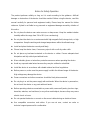
Notice for Safety Operation
The product performs reliably as long as it is used according to the guidance. Artificial
damage or destruction of the device should be avoided. Before using the device, read this
manual carefully for personal and equipment safety. Please keep the manual for further
reference. Kyland is not liable to any personal or equipment damage caused by violation of
this notice.
Do not place the device near water sources or damp areas. Keep the ambient relative
humidity within the range from 5% to 95% (non-condensing).
Do not place the device in an environment with high magnetic field, strong shock, or high
temperature. Keep the working and storage temperatures within the allowed range.
Install and place the device securely and firmly.
Please keep the device clean; if necessary, wipe it with a soft dry cotton cloth.
Do not place any irrelevant materials on the device or cables. Ensure adequate heat
dissipation and tidy cable layout without knots.
Wear antistatic gloves or take other protective measures when operating the device.
Avoid any exposed metal wires because they may be oxidized or electrified.
Install the device in accordance with related national and local regulations.
Before power-on, make sure the power supply is within the allowed range of the device.
High voltage may damage the device.
Power connectors and other connectors should be firmly interconnected.
Do not plug in or out the power supply with wet hands. When the device is powered on,
do not touch the device or any parts with wet hands.
Before operating a device connected to a power cable, remove all jewelry (such as rings,
bracelets, watches, and necklaces) or any other metal objects, because they may cause
electric shock or burns.
Do not operate the device or connect or disconnect cables during an electrical storm.
Use compatible connectors and cables. If you are not sure, contact our sales or
technical support personnel for confirmation.

Do not disassemble the device by yourself. When an anomaly occurs, contact our sales
or technical support personnel.
If any part is lost, contact our sales or technical support personnel to purchase the
substitute. Do not purchase parts from other channels.
Dispose of the device in accordance with relevant national provisions, preventing
environmental pollution.
These devices are open-type and are meant to be installed in an enclosure only
accessible with the use of a tool and suitable for the environment.
Specification of the internal fuses in this equipment: 3.15A/300V.
In the following cases, please immediately shut down your power supply and contact your
Kyland representative:
Water gets into the equipment.
Equipment damage or shell damage.
Equipment operation or performance has abnormally changed.
The equipment emits odor, smoke or abnormal noise.
The device shall be installed in the appropriate enclosure, if the equipment is used in a
manner not specified by the manufacturer, the protection provided by the equipment
may be impaired.
The following information applies when operating this device in hazardous locations:
Suitable for use in Class I, Division 2, Groups A, B, C and D Hazardous Locations, or
nonhazardous locations only.
Cet appareillage est utilisable dans les emplacements de Classe I, Division 2, Groupes A, B,
C et D, ou dans les emplacements non dangereux seulement.
WARNING: EXPLOSION HAZARD
Do not disconnect equipment while the circuit is live or unless the area is known to be
free of ignitable concentrations.
Substitution of any component may impair suitability for Class I, Division 2.
AVERTISSEMENT: RISQUE D'EXPLOSION

Avant de deconnecter l'equipement, couper le courant ou s'assurer que l'emplacement
est designe non dangereux.
La substitution de composants peut rendre ce materiel inacceptable pour les
emplacements de Classe I, Division 2.

I
Contents
1 Product Overview ...............................................................................................................1
2 Structure and Interface .......................................................................................................2
2.1 Front Panel ..................................................................................................................2
2.2 Top Panel .....................................................................................................................3
3 Mounting .............................................................................................................................4
3.1 Dimension Drawing ......................................................................................................4
3.2 Mounting Modes and Steps .........................................................................................4
3.2.1 DIN-Rail Mounting (Fixed in inside of Enclosure or Equipment only) ....................5
3.2.2 DIN-Rail Dismounting ............................................................................................5
3.2.3 Mounting clearance ...............................................................................................6
4 Connection .........................................................................................................................7
4.1 10/100Base-T(X) Ethernet Port ....................................................................................7
4.2 RS-232/RS-422/RS-485 interface ................................................................................8
4.3 Grounding ....................................................................................................................9
4.4 Power Terminal Block ..................................................................................................9
4.5 DIP switch .................................................................................................................. 11
5 Reset ................................................................................................................................ 13
6 LEDs ................................................................................................................................. 14
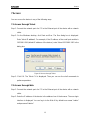
7 Access .............................................................................................................................. 15
7.1 Access through Telnet ............................................................................................... 15
7.2 Access through Web .................................................................................................. 15
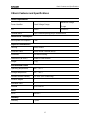
8 Basic Features and Specifications .................................................................................... 17
9 Appendix ........................................................................................................................... 18

Product Overview
1
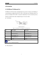
1 Product Overview
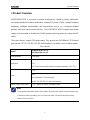
KGW3102/KPS3102 is a protocol converter developed by Kyland for factory automation,
wind power, distribution network automation, subway PIS, power SCADA, sewage treatment,
metallurgy, intelligent transportation, rail transportation and so on. It supports Modbus
gateway and serial server model selection. The KGW3102/KPS3102 supports dual power
supply, and can enable or disable the RS-485 terminal matching resistor by setting the DIP
switch.
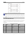
The series devices support DIN rail mounting. They provide one 10/100Base-T(X) Ethernet
port and two RS-232 / RS-422 / RS-485 serial interface. For details, see the following table.
Table 1 Models
Model
KGW3102-1T2D-L17-L17
KPS3102-1T2D- L17-L17
Code definition
Code option
KGW/KPS
KGW: Modbus gateway product model, operating temperature: -40℃
~75℃
KPS: Serial server product model, operating temperature: -40℃~75℃
Ports
1T2D
Note:
one 10/100Base-T(X) Ethernet port
two RS-232 / RS-422 / RS-485 serial interface
PWR1-PWR2: power input
L+-N-:24VDC(12-48VDC, redundant input)
Note:
For the product information listed in these tables, we reserve the right to amend it without notice.
To obtain the latest information, you can contact our sales or technical support personnel.
Power input is from SELV.

Structure and Interface
2
2 Structure and Interface
Caution:
It is recommended to purchase the port dustproof shield (optional) to keep ports clean and
ensure device performance.
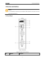
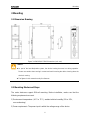
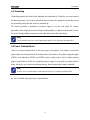
2.1 Front Panel
Figure 1 Front Panel
Table 2 Description of the Front Panel
No.
Identifier
Description

Structure and Interface
3
(1)
PWR1
Power 1 LED
(2)
PWR2
Power 2 LED
(3)
Run
Run LED
(4)
-
10/100Base-T(X) Ethernet port connection status LED (green)
(5)
-
10/100Base-T(X) Ethernet port speed LED (yellow)
(6)
E1
10/100Base-T(X) Ethernet port
(7)
Sn
RS-232/RS-422/RS-485 Serial interface
(8)
Sn-T
Serial interface to send data indicator (green)
(9)
Sn-R
Serial interface to receive data indicator (green)
Note:
In the above table, the value of n is 1, 2, for example, S1 is the serial port 1.
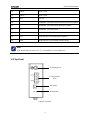
2.2 Top Panel
Grounding screw
Power terminal
block
DIP switch
Reset button
Figure 2 Top Panel

Mounting
4
3 Mounting
3.1 Dimension Drawing
Figure 3 KGW3102/KPS3102 Dimensions (unit: mm)
Caution:
As part of the heat dissipation system, the device housing becomes hot during operation.
Please use caution when coming in contact and avoid covering the device housing when the
device is running.
The figures in this manual are only for reference.
3.2 Mounting Modes and Steps
The series devicees support DIN-rail mounting. Before installation, make sure that the
following requirements are met.
1) Environment: temperature (-40℃ to 75℃), ambient relative humidity (5% to 95%,
non-condensing)
2) Power requirement: The power input is within the voltage range of the device.

Mounting
5
3) Grounding resistance: <5.
4) No direct sunlight, distant from heat source and areas with strong electromagnetic
interference.
5) The installation environment meets the ATEX / IECEx Certified IP40 requirements. No
direct touch, to avoid personal damage.
3.2.1 DIN-Rail Mounting (Fixed in inside of Enclosure or Equipment only)
Step 1: Select the mounting position for the device and guarantee adequate space and heat
dissipation (dimensions: 30mm×115mm×68mm).
Step 2: Insert the connecting seat onto the top of the DIN rail, and push the bottom of the
device inward and upward to ensure the DIN rail fits in the connecting seat. Make
sure the device is firmly installed on the DIN rail, as shown in the following figure.
Figure 4 DIN-Rail Mounting
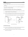
3.2.2 DIN-Rail Dismounting
Step 1: As shown in the following figure, press the device downward and move the device in
direction 1 until the bottom of the device is detached from the DIN rail.
Step 2: Pull the device upward and move the device in direction 2 until the device is removed
from the DIN rail completely.

Mounting
6
Figure 5 DIN-Rail Dismounting
3.2.3 Mounting clearance
It is recommended that there should be enough clearance to install this product:
Top and bottom side: 30mm
Sides:20mm
Front:30mm

Connection
7
4 Connection
4.1 10/100Base-T(X) Ethernet Port
10/100Base-T(X) Ethernet port is equipped with RJ45 connector. The port is self-adaptive. It
can automatically configure itself to work in 10M or 100M state, full or half duplex mode. The
port can also adapt to MDI or MDI-X connection automatically. You can connect the port to a
terminal or network device with a straight-through or cross-over cable.
Pin Definition
Figure 6 RJ45 Port
Table 3 Pin Definitions of 10/100Base-T(X) Ethernet Port
Pin
MDI-X Signal
MDI Signal
1
Receive Data+ (RD+)
Transmit Data+ (TD+)
2
Receive Data- (RD-)
Transmit Data- (TD-)
3
Transmit Data+ (TD+)
Receive Data+ (RD+)
6
Transmit Data- (TD-)
Receive Data- (RD-)
4, 5, 7, 8
Unused
Unused
Note:
"+" and "-" indicate level polarities.
Wiring Sequence

Connection
8
Figure 7 Connection Using Straight-through/Cross-over Cable
Note:
The color of the cable for RJ45 connector meets the 568B standard: 1-orange and white,
2-orange, 3-green and white, 4-blue, 5-blue and white, 6-green, 7-brown and white, and
8-brown.
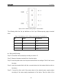
4.2 RS-232/RS-422/RS-485 interface
RS-232 / RS-422 / RS-485 interface using standard DB9 male interface, RS-232 interface to
support RTS / CTS. The serial interface pins supported by this device are defined in the
following table.
Table 4 Serial interface pin definition
Pin
RS-232
RS-422
RS-485
1
CTS
RxD-(B)
-
2
RxD
RxD+(A)
-
3
TxD
TxD-(Z)
Data-(B)
4
RTS
TxD+(Y)
Data+(A)
5
GND
GND
GND
6
–
–
–
7
–
–
–
8
–
–
–
9
–
–
–

Connection
9
4.3 Grounding
Grounding protects the device from lightning and interference. Therefore, you must ground
the device properly. You need to ground the device before it is powered on and disconnect
the grounding cable after the device is powered off.
The device provides a grounding screw(see Figure 2) on the rear panel for chassis
grounding. After crimping one end of the grounding cable to a cold pressed terminal, secure
the end to the grounding screw and connect the other end to the earth firmly.
Note:
Cross-sectional area of the chassis grounding cable>2.5mm
2
; grounding resistance<5.
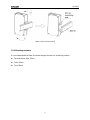
4.4 Power Terminal Block
There is a power terminal block on the rear panel of the device. You need to connect the
power wires to the terminal block to provide power to the device. The device supports single
(PWR1) and redundant (PWR1 and PWR2) power supply with a 4-pin 5.08mm-spacing
plug-in terminal block. When the redundant power supply is used and one power input is
faulty, the device can continue operating properly, thereby improving network reliability.
Note:
0.75mm
2
<Cross-sectional area of the power wire<2.5mm
2
; grounding resistance<5.
4-Pin 5.08mm-Spacing Plug-in Terminal Block

Connection
10
Figure 8 4-Pin 5.08mm-Spacing Plug-in Terminal Block
The following table lists the pin definitions of the 5-pin 5.08mm-spacing plug-in terminal
block.
Table 5 Pin Definitions of 4-Pin 5.08mm-Spacing Plug-in Terminal Block
No.
Signal
DC Definition
1
N/-
PWR1: -
2
L/+
PWR1: +
3
N/-
PWR2: -
4
L/+
PWR2: +
Wiring and Mounting
Step 1: Ground the device properly according to section 4.3.
Step 2: Remove the power terminal block from the device.
Step 3: Insert the power wires into the power terminal block according to Table 5 and secure
the wires.
Step 4: Insert the terminal block with the connected wires into the terminal block socket on
the device.
Step 5: Connect the other end of the power wires to the external power supply system
according to the power supply requirements of the device. View the status of the

Connection
11
power LEDs on the front panel. If the LEDs are on, the power is connected properly.
Wiring and Mounting should meet following specifications:
Table 6 Wiring and Mounting Specifications
Terminal Type
Required Torque
Wire Range (AWG)
Terminal Block Plug
5.0 lb-in for WEIDMUELLER terminal block
12-24
Caution:
Before connecting the device to power supply, make sure that the power input meets the
power requirement. If connected to an incorrect power input, the device may be damaged.
Waring: temperature of the cable used on this device is 85℃.
Warning:
Do not touch any exposed conducting wire, terminal, or component with a voltage warning
sign, because it may cause damage to humans.
Do not remove any part or plug in or out any connector when the device is powered on.
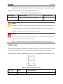
4.5 DIP switch
The top panel of the device has two DIP switches. Each DIP switch has ON and OFF status.
The default configuration is OFF. DIP switch can be achieved RS-485 serial terminal
matching resistor enable and disable, DIP switch 1-2 corresponding to the serial port S1-S2.
Figure 9 DIP switch
Table 7 Function description of DIP switch
DIP switch
Status
Function description
1
ON
Enable RS-485 terminal matching resistor for serial port S1

Connection
12
OFF
Disable RS-485 terminal matching resistor for serial port S1
2
ON
Enable RS-485 terminal matching resistor for serial port S2
OFF
Disable RS-485 terminal matching resistor for serial port S2

Reset
13
5 Reset
The device provides a Reset button on the top panel. The button can be used to restore
factory default settings.
You can restore factory default settings (including the IP address) by pressing and holding
the button for five seconds. The default IP address is E1: 192.168.0.249.

LEDs
14
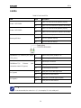
6 LEDs
Table 8 Front Panel LEDs
LED
State
Description
Power 1 LED-PWR1
On
Power 1 is connected and operates properly.
Off
Power 1 is not connected or operates abnormally.
Power 2 LED-PWR2
On
Power 2 is connected and operates properly.
Off
Power 2 is not connected or operates abnormally.
Running LED-Run
On
The CPU is starting up.
Blinking
The CPU operates properly.
Off
The CPU does not start up.
10/100Base-T(X) Ethernet port speed
LED (yellow)
On
100M working state (100Base-TX)
Off
10M working state (10Base-T) or no connection
10/100Base-T(X) Ethernet port
connection status LED (green)
On
Effective port connection
Blinking
Ongoing network activities
Off
No effective port connection
Sn-T(green)
Blinking
Serial port n has a data signal sent
Off
Serial port n No data transfer
Sn-R(green)
Blinking
Serial port n has data signal reception
Off
Serial port n No data transfer
Note:
In the above table, the value of n is 1, 2, for example, S1 is the serial port 1.
La page est en cours de chargement...
La page est en cours de chargement...
La page est en cours de chargement...
La page est en cours de chargement...
La page est en cours de chargement...
-
 1
1
-
 2
2
-
 3
3
-
 4
4
-
 5
5
-
 6
6
-
 7
7
-
 8
8
-
 9
9
-
 10
10
-
 11
11
-
 12
12
-
 13
13
-
 14
14
-
 15
15
-
 16
16
-
 17
17
-
 18
18
-
 19
19
-
 20
20
-
 21
21
-
 22
22
-
 23
23
-
 24
24
-
 25
25


KYLAND Technology KPS3102 Series Hardware Installation Manual
- Catégorie
- Convertisseurs de média réseau
- Taper
- Hardware Installation Manual
- Ce manuel convient également à
dans d''autres langues
- English: KYLAND Technology KPS3102 Series
Autres documents
-
Korenix JetPort 5801 Quick Installation Manual
-
 Allen-Bradley Stratix 2000 Installation Instructions Manual
-
 ANTAIRA LMX-0702G-SFP-V2 Series Manuel utilisateur
-
Weidmueller 2682600000 Guide d'installation
-
Westermo MDI-110-F3G Mode d'emploi
-
Korenix JetNet 3010 Series Quick Installation Manual
-
Renkforce GH-4200E+ Le manuel du propriétaire
-
Moxa NPort S9450I Series Guide d'installation rapide
-
 ANTAIRA LNX-C800-T Manuel utilisateur
-
red lion NT328G Hardware Manuel utilisateur


