Fisher & Paykel HC30DTXB2_N Guide d'installation
- Catégorie
- Hottes
- Taper
- Guide d'installation
Ce manuel convient également à

INSTALLATION GUIDE/USER GUIDE
GUIDE D’INSTALLATION/GUIDE D’UTILISATION
US CA
CHIMNEY BOX
VENTILATION HOOD
HC24DTXB2, HC30DTXB2 & HC36DTXB2 models
HOTTE DE VENTILATION
MURALE DÉCORATIVE
Modèles HC24DTXB2, HC30DTXB2 & HC36DTXB2

English Page 1 – 22
Français
Page 25 – 46

1
IMPORTANT!
SAVE THESE INSTRUCTIONS
The models shown in this user guide
may not be available in all markets
and are subject to change at any time.
For current details about model and
specification availability in your country,
go to our website fisherpaykel.com or
contact your local Fisher & Paykel dealer.
Registration
Register your product with us so we can
provide you with the best service possible.
To register your product visit our website:
fisherpaykel.com
EN
Introduction 3
Safety and warnings 4
Installation instructions 6
Operating instructions 18
Cleaning and maintenance 19
Parts and accessories 21
Service and Warranty 22
CONTENTS


3
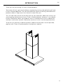
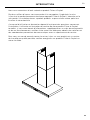
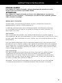
INTRODUCTION
Thank you for purchasing a Fisher & Paykel product.
Thousands of hours go into the design, engineering, testing and perfecting of each
Fisher & Paykel appliance. The care and attention given to creating these beautiful
products doesn’t stop once it has found its home with you.
This use and care manual will answer most of your questions about the set-up, use
and on-going maintenance of your Fisher & Paykel product; however if you require
further information about your product and its use please consult our website for
solutions and further contact information to discuss with a service representative.
To ensure you receive all relevant product updates and the best service possible,
registeryour Fisher & Paykel products through our website.
EN


5
SAFETY AND WARNINGS
– When cutting or drilling into wall or ceiling, do not damage electrical wiring
andother hidden utilities.
– Ducted fans must always be vented to the outdoors.
– This unit must be grounded.
●CAUTION: To reduce risk of fire and to properly exhaust air, be sure to duct air
outside—Do not vent exhaust air into spaces within walls or ceilings or into attics,
crawl spaces, or garages.
●WARNING: To reduce the risk of fire, use only metal ductwork.
●WARNING: To reduce the risk of fire or electric shock, do not use this fan with
any solid-state speed control device.
●WARNING: To reduce the risk of a range top grease fire:
– Never leave surface units unattended at high settings. Boilovers cause
smoking and greasy spillovers that may ignite. Heat oils slowly on low or
medium settings.
– Always turn hood ON when cooking at high heat or when flambéing food
(ieCrepes Suzette, Cherries Jubilee, Peppercorn Beef Flambé)
– Clean ventilating fans frequently. Grease should not be allowed to
accumulate on fan or filter.
– Use proper pan size. Always use cookware appropriate for the size of
the surface element.
●WARNING: To reduce the risk of injury to persons in the event of a range top
grease fire, observe the following*:
– SMOTHER FLAMES with a close-fitting lid, cookie sheet, or metal tray, then
turn off the burner. BE CAREFUL TO PREVENT BURNS. If the flames do not
go out immediately, EVACUATE AND CALL THE FIRE DEPARTMENT.
– NEVER PICK UP A FLAMING PAN—You may be burned.
– DO NOT USE WATER, including wet dishcloths or towels—a violent steam
explosion will result.
– Use an extinguisher ONLY if:
– You know you have a Class ABC extinguisher, and you already know
how to operate it.
– The fire is small and contained in the area where it started.
– The fire department is being called.
– You can fight the fire with your back to an exit.
●WARNING: Unplug or disconnect the appliance from the power supply before
servicing or cleaning.
●CAUTION: To reduce the risk of fire and electric shock when product is used in
recirculation mode, use only conversion kit model 792580 Recirculation Diverter
and791772Recirculation Carbon Filter x2.
READ AND SAVE THESE INSTRUCTIONS
* Based on “Kitchen Firesafety Tips” published by NFPA.
EN

6
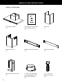
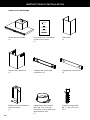
INSTALLATION INSTRUCTIONS
Contents of packaging
Upper chimney bracket
(1)
Installation instructions
User guide manual
(1)
Chimney
(1)
6” (152mm) diameter
Ducting adapter with
back draft damper
(1)
1⁄” (30mm)
Expansion plug
(10)
Upper chimney
(1)
Ventilation hood
(1)
Power connection box
(1)
Chimney bracket
(1)
US CA
CH MNEY BOX
VENTILAT ON HOOD
HOTTE DE VENTILATION
MURALE DÉCORAT VE

7
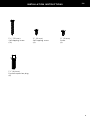
INSTALLATION INSTRUCTIONS
1⁄” (30mm)
Self tapping screw
(10)
⅜” (10mm)
Self tapping screw
(4)
1¾” (44mm)
Drywall expansion plug
(8)
⅜” (10mm)
Screw
(2)
EN

8
INSTALLATION INSTRUCTIONS
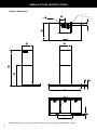
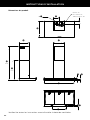
Please read the entire instructions before installing the ventilation hood.
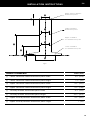
Product dimensions
h
i
C
j
g f
A
A
B
D
E
Ø
l
k
UL power
connection box
min
max

9
INSTALLATION INSTRUCTIONS
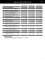
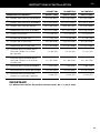
HC24DTXB2 HC30DTXB2 HC36DTXB2
PRODUCT DIMENSIONS inches (mm) inches (mm) inches (mm)
AMin overall height of product 23¾” (603) 23¾” (603) 23¾” (603)
AMax overall height of product 41⁄” (1043) 41⁄” (1043) 41⁄” (1043)
BOverall width of product 23⁄” (598) 29¾” (755) 35⅜” (898)
COverall depth of product 19⁄” (500) 19⁄” (500) 19⁄” (500)
DHeight of product 2⁄” (65) 2⁄” (65) 2⁄” (65)
EHeight of stainless steel face panel 1⁄” (36) 1⁄” (36) 1⁄” (36)
FWidth of chimney 12⅝” (320) 12⅝” (320) 12⅝” (320)
GDepth of chimney 11⁄” (290) 11⁄” (290) 11⁄” (290)
HDistance from center of ducting
outlet to back of product 3⅜” (85) 3⅜” (85) 3⅜” (85)
IDistance from center of ducting
outlet to side of chimney 6⁄” (160) 6⁄” (160) 6⁄” (160)
JDiameter of ducting outlet 6” (152) 6” (152) 6” (152)
KDistance between center of lights 9⅝” (244) 9⅝” (244) 9⅝” (244)
LDistance between center of lights
and back of product 1⅜” (35) 1⅜” (35) 1⅜” (35)
IMPORTANT!
Actual product dimensions may vary by ± ⁄”(2 mm).
EN

10
INSTALLATION INSTRUCTIONS
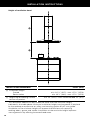
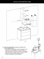
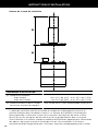
Height of ventilation hood
INSTALLATION DIMENSIONS inches (mm)
MInstallation height
Ducted
Recirculation
min. 24⁄” (627)–max. 43⁄” (1034)
min. 26⅞” (682)–max. 43⁄” (1034)
NHeight top of cooking surface
to base of product
min. 26” (660)–max. recommended 36” (915)
This ventilation hood must be installed no lower than the minimum height
indicated in the table above. Minimum installation height may be greater if required
by the cooktop manufacturer or safety and warning section of this user guide.
Installation at the minimum height will improve the efficiency of capturing
cooking odors, grease and smoke. Installation at the maximum height improves
user ergonomics by offering increased head room.
M
N

11
INSTALLATION INSTRUCTIONS
WARNING!
To reduce the risk of fire, use only metal ductwork. Do not use flexible plastic ducting
CAUTION!
To reduce risk of fire and to properly exhaust air, be sure to duct air outside—
do not vent exhaust air into spaces within walls or ceilings or into attics,
crawl spaces, or garages.
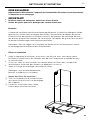
Venting options
Attention should be given to ensure that any applicable regulations concerning the
discharge of exhaust air are fulfilled.
The ventilation hood can be installed to operate with the exhaust air ducted
externally from the kitchen, or installed to operate with the exhaust air recirculating
within the kitchen.
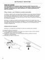
Ducted
For ducted installation it is recommended that 6” (152 mm) diameter, rigid or semi-rigid
ducting is used. This will require a 6⁄” (160 mm) (min) round hole in the ceiling or wall.
Care should be taken to position the hole correctly.
For optimal efficiency use the shortest and straightest duct route possible and use
rigid or semi-rigid ducting for reduced noise and increased airflow. Flexible metal
ducting should only be used as a last resort (ie in difficult installations) and if used
ensure that it is straight and smooth and extended as much as possible.
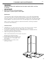
Recirculating
To enable the product to operate with the air recirculating, purchase a recirculation
diverter and carbon filters or recirculation kit (refer to the ‘Parts and accessories’
section). This recirculation diverter is required to channel the air out the side vents
at the top of the chimney and the carbon filters are required to remove odors.
Note: a ducting hole is not required in the wall or ceiling if the ventilation hood is
installed to operate with exhaust air recirculating.
EN


13
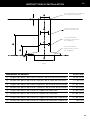
INSTALLATION INSTRUCTIONS
PRODUCT DIMENSIONS inches (mm)
oLower ventilation hood attachment point width 20” (508)
PLower ventilation hood attachment point height 1⁄” (43)
qUpper ventilation hood attachment point width 9⅞” (250)
rUpper ventilation hood attachment point height 11⁄” (288)
sChimney bracket attachment point width 9¼” (235)
tChimney bracket attachment point height 22¼” (566)
uUpper chimney bracket attachment point width 9⅞” (250)
vUpper chimney bracket attachment point height 1” (25)
Fig.2
Upper chimney bracket
attachment points
Chimney bracket
attachment points
Upper ventilation
hood attachment point
Lower ventilation
hood attachment point
u
o
v
t
r
p
q
s
EN


15
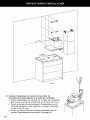
INSTALLATION INSTRUCTIONS
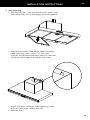
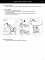
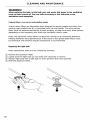
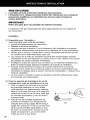
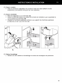
4 Wall mounting
●Remove the filters—pull the relative catch and tilt the
filter downwards until it disengages from the supports.
●Hang the ventilation hood off the upper ventilation
hood mounting screws with ⁄” (2 mm) gap.
Hang off the keyhole attachment points on the back
of the ventilation hood then tighten the screws.
●Attach the lower ventilation hood mounting screws
to fix the ventilation hood to the wall.
●Refit the filters.
EN

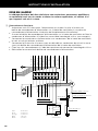
16
INSTALLATION INSTRUCTIONS
WARNING!
Electrical wiring must be done by qualified person(s) in accordance with
all applicable codes and standards and the unit must be grounded.
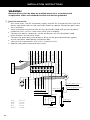
5 Electrical connection
●Run three wires, two for the power supply and one for the ground wire, from the
power connection box on the ventilation hood to a power connection point near
the installation.
●Open the power connection box on the ventilation hood and secure the power
conductor with a cULus listed strain relief (not included).
●Connect the power conductors to the conductors for the ventilation hood,
black to black and white to white.
●Connect the grounding wire (green or bare) to the ground conductor (green)
of the ventilation hood power connection box.
●Secure all the connections with cULus listed wire nuts.
●Replace the power connection box cover.
M
Switch
Interrupteur
Brown/Marron
Gray/Gris
Black/Noir
Red/Rouge
Blue/Bleu
Purple/Violet
White/Blanc
Yellow/Green
Jaune/Vert
White/Blanc
Yellow/Green Jaune/VertGround
Brown/Marron Motor
Gray/Gris
Black/Noir
Red/Rouge
Blue/Bleu
Black/Noir
White/Blanc
Black/Noir (L)
White/Blanc (N)
Green/Vert (E)
Black/Noir
Black/Noir
White/Blanc Motor
Orange/Orange Motor
Capacitor
Bornier
Junction
Box
Green/Vert
120V~60Hz
Gray 4 speed
Black 3 speed
Red 2 speed
Blue 1 speed
Brown (neutral)
Lamp/Lampes


La page est en cours de chargement...
La page est en cours de chargement...
La page est en cours de chargement...
La page est en cours de chargement...
La page est en cours de chargement...
La page est en cours de chargement...
La page est en cours de chargement...
La page est en cours de chargement...
La page est en cours de chargement...
La page est en cours de chargement...
La page est en cours de chargement...
La page est en cours de chargement...
La page est en cours de chargement...
La page est en cours de chargement...
La page est en cours de chargement...
La page est en cours de chargement...
La page est en cours de chargement...
La page est en cours de chargement...
La page est en cours de chargement...
La page est en cours de chargement...
La page est en cours de chargement...
La page est en cours de chargement...
La page est en cours de chargement...
La page est en cours de chargement...
La page est en cours de chargement...
La page est en cours de chargement...
La page est en cours de chargement...
La page est en cours de chargement...
La page est en cours de chargement...
La page est en cours de chargement...
La page est en cours de chargement...
La page est en cours de chargement...
-
 1
1
-
 2
2
-
 3
3
-
 4
4
-
 5
5
-
 6
6
-
 7
7
-
 8
8
-
 9
9
-
 10
10
-
 11
11
-
 12
12
-
 13
13
-
 14
14
-
 15
15
-
 16
16
-
 17
17
-
 18
18
-
 19
19
-
 20
20
-
 21
21
-
 22
22
-
 23
23
-
 24
24
-
 25
25
-
 26
26
-
 27
27
-
 28
28
-
 29
29
-
 30
30
-
 31
31
-
 32
32
-
 33
33
-
 34
34
-
 35
35
-
 36
36
-
 37
37
-
 38
38
-
 39
39
-
 40
40
-
 41
41
-
 42
42
-
 43
43
-
 44
44
-
 45
45
-
 46
46
-
 47
47
-
 48
48
-
 49
49
-
 50
50
-
 51
51
-
 52
52


Fisher & Paykel HC30DTXB2_N Guide d'installation
- Catégorie
- Hottes
- Taper
- Guide d'installation
- Ce manuel convient également à