Watts G1070 Guide d'installation
- Catégorie
- Articles sanitaires
- Taper
- Guide d'installation

ENGLISH INSTRUCTIONS
IS-G1070_GP1070 1314 EDP# 1916202 © 2013 Watts
USA: 815 Chestnut St., No. Andover, MA 01845-6098; www.watts.com
Canada: 5435 North Service Rd., Burlington, ONT. L7L 5H7; www.wattscanada.ca
Limited Warranty: Watts Regulator Co. (the “Company”) warrants each product to be free from defects
in material and workmanship under normal usage for a period of one year from the date of original ship-
ment. In the event of such defects within the warranty period, the Company will, at its option, replace
or recondition the product without charge.
THE WARRANTY SET FORTH HEREIN IS GIVEN EXPRESSLY AND IS THE ONLY WARRANTY
GIVEN BY THE COMPANY WITH RESPECT TO THE PRODUCT. THE COMPANY MAKES NO OTHER
WARRANTIES, EXPRESS OR IMPLIED. THE COMPANY HEREBY SPECIFICALLY DISCLAIMS ALL
OTHER WARRANTIES, EXPRESS OR IMPLIED, INCLUDING BUT NOT LIMITED TO THE IMPLIED
WARRANTIES OF MERCHANTABILITY AND FITNESS FOR A PARTICULAR PURPOSE.
The remedy described in the first paragraph of this warranty shall constitute the sole and exclusive
remedy for breach of warranty, and the Company shall not be responsible for any incidental, special
or consequential damages, including without limitation, lost profits or the cost of repairing or replacing
other property which is damaged if this product does not work properly, other costs resulting from labor
charges, delays, vandalism, negligence, fouling caused by foreign material, damage from adverse water
conditions, chemical, or any other circumstances over which the Company has no control. This warranty
shall be invalidated by any abuse, misuse, misapplication, improper installation or improper maintenance
or alteration of the product.
Some States do not allow limitations on how long an implied warranty lasts, and some States do not allow
the exclusion or limitation of incidental or consequential damages. Therefore the above limitations may
not apply to you. This Limited Warranty gives you specific legal rights, and you may have other rights
that vary from State to State. You should consult applicable state laws to determine your rights. SO
FAR AS IS CONSISTENT WITH APPLICABLE STATE LAW, ANY IMPLIED WARRANTIES THAT MAY NOT
BE DISCLAIMED, INCLUDING THE IMPLIED WARRANTIES OF MERCHANTABILITY AND FITNESS FOR
A PARTICULAR PURPOSE, ARE LIMITED IN DURATION TO ONE YEAR FROM THE DATE OF ORIGINAL
SHIPMENT.
IS-G1070_GP1070 1314 EDP# 1916202 © 2013 Watts
USA: 815 Chestnut St., No. Andover, MA 01845-6098; www.watts.com
Canada: 5435 North Service Rd., Burlington, ONT. L7L 5H7; www.wattscanada.ca
Garantía limitada: Watts Regulator Co. (en adelante, “la Compañía”) garantiza, por un período de un año a
partir de la fecha de envío original, que sus productos están libres de defectos en materiales y mano de obra
bajo condiciones de uso normal. En caso de que se encuentren tales defectos dentro del período de garantía, la
Compañía reemplazará o reacondicionará, a su elección, el producto sin costo alguno.
LA GARANTÍA AQUÍ ESTIPULADA SE OTORGA EN FORMA EXPRESA Y ES LA ÚNICA GARANTÍA
OTORGADA POR LA COMPAÑÍA EN RELACIÓN CON EL PRODUCTO. LA COMPAÑÍA NO OTORGA NINGUNA
OTRA GARANTÍA, YA SEA EXPRESA O IMPLÍCITA. LA COMPAÑÍA POR LA PRESENTE DESCONOCE
ESPECÍFICAMENTE TODAS LAS DEMÁS GARANTÍAS, EXPRESAS O IMPLÍCITAS, INCLUIDAS A TÍTULO
ENUNCIATIVO Y NO LIMITATIVO, LAS GARANTÍAS IMPLÍCITAS DE APTITUD PARA LA COMERCIALIZACIÓN
E IDONEIDAD PARA UN PROPÓSITO EN PARTICULAR.
La solución descrita en el primer párrafo de esta garantía constituirá la única y exclusiva solución por
incumplimiento de garantía, y la Compañía no se hará responsable por daños incidentales, especiales o
indirectos, incluidos a título enunciativo y no limitativo, el lucro cesante o el costo de reparación o reemplazo de
otra propiedad que resulte dañada por el mal funcionamiento de este producto, otros costos resultantes por mano
de obra, demoras, vandalismo, negligencia, obstrucciones ocasionadas por materiales extraños, daños debidos a
condiciones adversas del agua, productos químicos o cualquier otra circunstancia sobre la cual la Compañía no
tenga control. Esta garantía no tendrá validez en cualquier caso de maltrato, uso indebido, aplicación incorrecta,
instalación o mantenimiento inadecuados o alteración del producto.
Algunos Estados no permiten limitaciones en la duración de una garantía implícita o la exclusión o limitación de
daños incidentales o indirectos. Por lo tanto, es posible que las limitaciones anteriores no correspondan en su
caso. Esta garantía limitada le da derechos legales específicos; usted podría tener también otros derechos que
varían según el Estado. Usted debe consultar las leyes estatales aplicables para determinar sus derechos. EN EN
LA MEDIDA EN QUE SEA CONGRUENTE CON LAS LEYES ESTATALES APLICABLES, CUALQUIER GARANTÍA
IMPLÍCITA QUE NO SEA RECHAZADA, INCLUIDAS LAS GARANTÍAS IMPLÍCITAS DE APTITUD PARA LA
COMERCIALIZACIÓN E IDONEIDAD PARA UN PROPÓSITO EN PARTICULAR, SE LIMITA EN SU DURACIÓN A
UN AÑO A PARTIR DE LA FECHA DEL ENVÍO ORIGINAL.
USA : 815 Chestnut St., No. Andover, MA 01845-6098; www.watts.com
Canada : 5435 North Service Rd., Burlington, ONT. L7L 5H7; www.wattscanada.ca
Garantie limitée : Watts Regulator Co. (la « Société ») garantit que chacun de ses produits est exempt de
vice de matériau et de fabrication dans des conditions normales d’utilisation pour une période d’un an à
compter de la date d’expédition d’origine. Dans l’éventualité où de tels vices se manifesteraient pendant
la période de garantie, la Société, à sa discrétion, remplacera ou reconditionnera le produit sans frais.
LA PRÉSENTE GARANTIE EST EXPRESSE ET REPRÉSENTE LA SEULE GARANTIE OFFERTE PAR
LA SOCIÉTÉ POUR CE PRODUIT. LA SOCIÉTÉ N’OFFRE AUCUNE AUTRE GARANTIE, EXPRESSE OU
TACITE. PAR LA PRÉSENTE, LA SOCIÉTÉ REJETTE SPÉCIFIQUEMENT TOUTE AUTRE GARANTIE,
EXPRESSE OU TACITE, NOTAMMENT TOUTE GARANTIE TACITE DE QUALITÉ MARCHANDE OU
D’ADAPTATION À UN BUT PARTICULIER.
Le recours décrit dans le premier paragraphe de cette garantie constitue le seul recours à toute violation
de la présente garantie. La Société ne saurait être tenue responsable de tout dommage accessoire,
spécial ou indirect, y compris, de façon non limitative : la perte de profits ou le coût afférent à la
réparation ou au remplacement d’autres biens qui seraient endommagés par suite du fonctionnement
incorrect dudit produit ; d’autres coûts résultant de frais de main-d’oeuvre, de retards, de vandalisme,
de négligence, d’une obstruction causée par des matériaux étrangers, de dommages causés par une
eau impropre, des produits chimiques ou par tout autre événement échappant au contrôle de la Société.
La présente garantie est déclarée nulle et non avenue en cas d’usage abusif ou incorrect, d’application,
d’installation ou d’entretien incorrects ou de modification du produit.
Certains États n’autorisent pas les limitations de durée d’une garantie tacite ou l’exclusion ou la
limitation des dommages accessoires ou indirects. Les limitations susmentionnées peuvent donc ne pas
s’appliquer à vous. Cette garantie limitée vous donne des droits spécifiques et il se peut que vous ayez
aussi d’autres droits qui varient d’un État à l’autre. Veuillez vous référer aux lois applicables de l’État
pour déterminer vos droits en la matière. LA MESURE PERMISE PAR LA LOI APPLICABLE DE L’ÉTAT,
TOUTES LES GARANTIES TACITES NE POUVANT PAS ÊTRE REJETÉES, Y COMPRIS LES GARANTIES
TACITES DE QUALITÉ MARCHANDE ET D’ADAPTATION À UN BUT PARTICULIER, SONT LIMITÉES
QUANT À LEUR DURÉE À UN AN À COMPTER DE LA DATE D’EXPÉDITION D’ORIGINE.
IS-G1070_GP1070 1314 EDP# 1916202 © 2013 Watts
Series G1070 and GP1070
Series G1070 y GP1070
Séries G1070 et GP1070
LavSafe
™
Thermostatic Faucet
with Gooseneck Spout
Grifo termostático LavSafe
™
con pico cuello de cisne
Robinet thermostatique
LavSafe
™
avec col de cygne
Installation Instructions
Instrucciones de instalación
Instructions d’installation
IS-G1070_GP1070
Certied to NSF/ANSI 61
Section 9-G
WARNING: This product contains chemicals known to the
State of California to cause cancer and birth defects or other
reproductive harm.
For more information: www.watts.com/prop65
ADVERTENCIA: Este producto contiene sustancias químicas
que en el Estado de California se conocen como causantes
de cáncer y malformaciones u otros daños reproductivos.
Para más información: www.watts.com/prop65
AVERTISSEMENT: Ce produit contient des produits chi-
miques reconnus par l’État de Californie comme étant can-
cérigènes et pouvant provoquer des anomalies congénitales
ou affecter la capacité de reproduction.
Pour plus d'informations: www.watts.com/prop65
Specifications
Connections ........................................................ 3/8" compression inlets with
checks
Maximum Operating Pressure ............................. 125psi (861 kPa)
Maximum Hot Water Temperature ...................... 194°F (90°C)
Minimum Hot Water Supply Temp. ..................... 5°F (3°C) Above Set-Point
Temperature Adjustment Range ......................... 60 - 120°F (15 - 49°C)
Minimum Flow .................................................... 0.5 gpm (2.2 lpm)
Cold Water Inlet Temperature Range ................... 39 - 80°F (4 - 27°C)
Hot Water Inlet Temperature Range .................... 120 - 180°F (49 - 82°C)
Listing ................................................................ ASSE 1070, IAPMO cUPC
Approval Standards ............................................ ASSE 1070, CSA B125.3,
NSF 61 Section 9 Annex G
Installation Instructions
1. Flush all piping thoroughly before installing.
2. The installation and field adjustment of LavSafe
™
faucet is the responsibility of the
installer and shall be carried out in accordance with the following steps.
3. Attach threaded rod to faucet body.
For 3 holes 8" centers (Series GP1070)
1. Place gasket and threaded rod under the base plate. Place base plate over the hole.
2. Place washer on the threaded rod and tighten with the wing nut. Faucet control should
be on the right.
3. Install washer on the base of the gooseneck spout and secure it with the shank nut on
the center hole.
4. Position faucet body with O-ring on the base plate.
5. Install supply tubes with check valves to hot and cold inlets.
Inlets are marked "H" and "C" underneath the faucet body. Install faucet outlet tube to
body. Make sure O-rings are in place.
WARNING
!
SUPPLY TUBES –HAND TIGHTEN ONLY! Over tightening , using lubricants or exposure to
corrosive materials can damage supply tube threads and cause failure, leaking, or flood
and property damage.
6. Install washer on the threaded rod and tighten with mounting nut.
7. Connect gooseneck spout to faucet body using flexible supply.
8. Connect supply tubes to water supplies.
9. With the handle in "off" position, turn on water supplies and check for leaks.
10. Remove aerator and turn faucet to hot and cold water position to flush the line thoroughly.
Replace
aerator.
Troubleshooting
Faucet Drip
Remove cartridge and clean sealing areas on cartridge and the faucet body.
Reassemble and reset outlet temperature (refer to temperature adjustment section)
Outlet temperature is too hot or too cold
Check temperature limit stop setting (refer to temperature adjustment section)
The flow of water is insufficient or completely shutoff
Check that supply line valves are open. Remove aerator and clean.
Installation Instructions (cont.)
Part List
Index Description
1 Handle Kit 4"
2 Handle Kit 6"
3 Cartridge Kit
4 Aerator 2.0 gpm
5 Base Plate
6 Faucet Mounting Hardware
7 Supply Tubes
Min. Flow
to ASSE 1070
C
V
10psi
(69 kPa)
20psi
(138 kPa)
30psi
(207 kPa)
45psi
(310 kPa)
60psi
(414 kPa)
0.5 gpm
1.89 lpm
0.345
1.08 gpm
4.09 lpm
1.53 gpm
5.79 lpm
1.88 gpm
7.12 lpm
2.30 gpm
8.71 lpm
2.60 gpm
9.48 lpm
Capacity Table
*
*Less aerator & outlet temperature of 105°F (41°C)
For two holes (Series G1070)
1. Install supply tubes with
check valves to hot and
cold inlets. Inlets are
marked "H" and "C" under-
neath the faucet body.
Install faucet outlet tube
to body. Make sure
O-rings are in place.
WARNING
!
SUPPLY TUBES –HAND
TIGHTEN ONLY! Over tighten-
ing , using lubricants or exposure to corrosive materials can damage supply tube threads
and cause failure, leaking, or flood and property damage.
2. Install washer on the base of the gooseneck spout and secure it with the shank nut on the
sink.
3. Position faucet body with O-ring on the sink.
4. Install washer on the threaded rod and tighten with mounting nut.
5. Connect gooseneck spout to faucet body using flexible supply.
6. Connect supply tubes to water supplies.
7. With the handle in "off" position, turn on water supplies and check for leaks.
8. Remove aerator and turn faucet to hot and cold water position to flush the line thoroughly.
Replace aerator.
Temperature Adjustment
Maximum temperature setting adjustment must be set on the job to no greater than 105°F (41°C).
1. Remove handle by unscrewing set screw with allen wrench provided. Remove shroud.
2. Loosen two high temperature limit stop screws.
3. Replace handle and rotate handle clockwise to desired outlet temperature.
4. Remove handle and slide high temperature limit stop on inner bonnet ring, sliding it coun-
terclockwise until it contacts cartridge lever.
WARNING
!
Do not exceed temperature above 105°F (41°C).
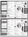
GOOSENECK SPOUT
SHANK
NUT
WASHER
WING NUT
THREADED ROD
FLEXIBLE SUPPLY
HANDLE
BASE PLATE
AERATOR
FAUCET BODY
THREADED
ROD
WASHER
MOUNTING
NUT
HOT WATER
SUPPLY
GASKET
COLD WATER
SUPPLY
5. Tighten high temperature limit stop screws.
6. Install shroud and handle.
7. Turn handle to maximum hot
position and verify temperature
setting.
Temperature Adjustment (cont.)
SET SCREW
INNER
BONNET
RING
HANDLE
SHROUD
CARTRIDGE
LEVER
SCREWS
HIGH
TEMPERA-
TURE
LIMIT STOP
1, 2
4
5
7
3
6
WARNING
!
Read this Manual BEFORE using this equipment.
Failure to read and follow all safety and use information can result
in death, serious personal injury, property damage, or damage to the
equipment.
Keep this Manual for future reference.
FAILURE TO COMPLY WITH PROPER INSTALLATION AND MAINTENANCE
INSTRUCTIONS COULD CONTRIBUTE TO THE VALVE FAILURE, RESULTING IN
INJURY AND/OR DEATH.
TO ENSURE THE ACCURATE AND RELIABLE OPERATION OF THIS PRODUCT,
IT IS ESSENTIAL TO:
• Properlydesignthesystemtominimizepressureandtemperaturevariations.
• Conductanannualmaintenanceprogramtoensureproperoperationof
all critical components.
• Thisvalveisnotfactorypresetandcanbeadjustedtodeliverscalding
temperatures. Check outlet temperature to ensure it does not exceed 105°F
(41°C). Make sure temperature limit stop is properly re-set to maximum
105°F (41°C) following valve maintenance or repair. Tampering with limit
stop in any way may result in scalding temperature causing serious bodily
harm and/or death.
WARNING
WARNING
!
WARNING
!
Need for Periodic Inspection: Periodic inspection by a licensed contractor
is recommended. Corrosive water conditions, and/or unauthorized adjust-
ments or repair could render the valve ineffective for service intended.
Regular checking and cleaning of the valve’s internal components and
check stops helps assure maximum life and proper product function.
Frequency of cleaning and inspection depends upon local water conditions.

INSTRUCCIONES EN ESPAÑOL
INSTRUCTIONS EN FRANçAIS
Fiches techniques
Connexions .................................................................... Entrées de compression de 0,9cm
(3/8 po) avec clapets
Pression maximale ......................................................... 125 lb/po
2
(8,6 bar)
Température d’eau chaude maximale ............................. 90 °C (194 °F)
Température minimale de
l’alimentation en eau chaude ......................................... 3 °C (5 °F) au-dessus de la valeur de
réglage
Plage de réglage de la température ................................ 15 °C à 49 °C (60 °F à 120 °F)
Débit minimal .................................................................. 2,2 l/m (0,5 gpm)
Plage de température de l’entrée
d’eau froide ..................................................................... 4 °C à 27 °C (39 °F à 80 °F)
Plage de température de l’entrée d’eau chaude ............... 49 °C à 82 °C (120 °F à 180 °F)
Inscription ..................................................................... ASSE 1070, IAPMO cUPC
Normes d’approbation ................................................... ASSE 1070, CSA B125.3,
NSF 61 Section 9 Annexe G
Instructions d’installation
1.Purgeztoutelatuyauterieàfondavantl’installation.
2.L’installationetleréglagesurplacedurobinetLavSafe™sontlaresponsabilitédel’installateuret
cesprocéduresdoiventêtreeffectuéesselonlesétapessuivantes.
3.Attachezlatigeletéeaurobinet.
Pour 3 centres de 20,3 cm (8 po) (Série GP1070)
1.Placezlejointetlatigeletéesouslaplaquedebase.Placezlaplaquedebasepar-dessusletrou.
2.Placezlarondelled'étanchéitésurlatigeletéeetserrezavecl’écrouàoreilles.Lacommandedu
robinetdoitêtreàdroite.
3.Installezlarondelled'étanchéitéàlabasedubecducoldecygneetxez-laavecl’écroudelatige
sur le trou central.
4.Positionnezlerobinetaveclejointtoriquesurlaplaquedebase.
5.Installezlestubesd’alimentationaveclesclapetsdenon-retourauxentréesd’eauchaudeetd’eau
froide.
Lesraccordsd’entréesontmarquésd’un«H»etd’un«C»souslerobinet.Installezletubedesor-
tie aurobinet.Veillezàcequelesjointstoriquessoientbienenplace.
AVERTISSEMENT
!
Serrer le tuyau d’alimentation à la main seul !
Leresserrementexcessifenemployantdel’huiledegraissageouàl’expositionauxmatériaux
corrosifs,pourraitcauserlesdommagesdesletagesdutuyaud’alimentationetencauserl’échec,
lafuiteouledélugeetledommagedesmatériaux.
6.Installezlarondelled'étanchéitésurlatigeletéeetserrezavecl'écroudemontage.
7.Raccordezlebecducoldecygneaurobinetaumoyend’untuyauexible.
8.Raccordezlestubesd’alimentationauxsourcesd’eau.
9.Aveclapoignéeàlaposition«off»(fermée),ouvrezlesalimentationseneauetvériezl’absencede
fuites.
10.Enlevezl’aérateurettournezlerobinetauxpositionschaudeetfroidepourpurgerlaligneàfond.
Replacezl’aérateur.
Pour deux trous (Série G1070)
1.Installezlestubes
d’alimentationavecles
clapets de non-retour aux
entréesd’eauchaudeetd’eau
froide.Lesraccordsd’entrée
sontmarquésd’un«H»et
d’un«
C»souslerobinet.
Installezletubedesortieau
robinet.Veillezàcequeles
jointstoriquessoientbienen
place.
AVERTISSEMENT
!
Serrer le tuyau d’alimentation à
la main seul !
Le resserrement excessif
enemployantdel’huiledegraissageouàl’expositionauxmatériauxcorrosifs,pourraitcauserles
dommagesdesletagesdutuyaud’alimentationetencauserl’échec,lafuiteouledélugeetle
dommagedesmatériaux.
2.Installezlarondelled'étanchéitéàlabasedubecducoldecygneetxez-laavecl’écroudelatigesur
l’évier.
3.Positionnezlerobinetaveclejointtoriquesurl’évier.
4.Installezlarondelled'étanchéitésurlatigeletéeetserrezavecl'écroudemontage.
5.Raccordezlebecducoldecygneaurobinetaumoyend’untuyauexible.
6.Raccordezlestubesd’alimentationauxsourcesd’eau.
7.Aveclapoignéeàlaposition«off»(fermée),ouvrezlesalimentationseneauetvériezl’absence
de fuites.
8.Enlevezl’aérateurettournezlerobinetauxpositionschaudeetfroidepourpurgerlaligneàfond.
Replacezl’aérateur.
Réglage de la température
L’ajustementduréglagedelatempératuremaximaledoitêtrefaitsurplaceetnedoitpasdépasser41°C(105°F).
1.EnlevezlapoignéeendévissantlavispressionaveclacléAllen.Enlevezleasque.
2.Desserrezlesdeuxvisdebutéedelimitedetempératureélevée.
3.Replacezlapoignéeetfaites-lapivoterdanslesensdesaiguillesd’unemontrejusqu’àlatempératurede
sortiedésirée.
4.Enlevezlapoignéeet,danslesenscontraireauxaiguillesd’unemontre,faitesglisserlabutéedelimite
Dépannage
Égouttement du robinet
Enlevezlacartoucheetnettoyezlesjointsd’étanchéitéetlerobinet.Réassemblezetréinitialisez
latempératuredesortie(consultezlasectionderéglagedelatempérature).
La température de sortie est trop chaude ou trop froide
Vériezleréglagedelabutéedelimitedetempérature(consultezlasectionderéglagedela
température).
Le débit d’eau est insuffisant ou complètement fermé
Vériezsilessoupapesdelaligned’alimentationsontouvertes.Enlevezl’aérateuretnettoyez-le.
Instructions d’installation (suite)
Liste des pièces
Index Description
1 Trousse de poignée de
10,16 cm (4 po)
2 Trousse de poignée de
15,24 cm (6 po)
3 Trousse de cartouche
4 Aérateur de 7,5 l/min
(2,0 gpm)
5 Plaque de base
6
Quincaillerie de montage
du robinet
7 Tubes d’alimentation
Débit minimal à
ASSE 1070
C
V
69 kPa
(10 lb/po
2
)
138 kPa
(20 lb/po
2
)
207 kPa
(30 lb/po
2
)
310 kPa
(45 lb/po
2
)
414 kPa
(60 lb/po
2
)
1,89 l/m
(0,5 gpm)
0,345
4,09 l/m
(1,08 gpm)
5,79 l/m
(1,53 gpm)
7,12 l/m
(1,88 gpm)
8,71 l/m
(2,30 gpm)
9,48 l/m
(2,60 gpm)
Tableau de capacité
*
*Moins la température de 41 °C (105 °F) de l’aérateur et de la sortie
BEC DU COL DE CYGNE
ÉCROU
DE LA
TIGE
RONDELLE
D'ÉTANCHÉITÉ
ÉCROU À
OREILLES
TIGE FILETÉE
TUYAU FLEXIBLE
POIGNÉE
PLAQUE DE BASE
AÉRATEUR
ROBINET
TIGE FILETÉE
RONDELLE
D’ÉTANCHÉITÉ
ÉCROU DE
MONTAGE
ALIMENTATION
EN EAU CHAUDE
JOINT
ALIMENTATION
EN EAU FROIDE
detempératureélevéesurl’anneauduchapeauintérieurjusqu’àcequ’elletouchelacar-
toucheàlevier.
AVERTISSEMENT
!
La température ne doit pas être supéri-
eure à 41 °C (105 °F).
5.Serrezlesvisdebutéedelimitede
températureélevée.
6.Installezleasqueetlapoignée.
7.
Tournez la poignée au maximum
de la position chaude et vérifiez le
réglage de la température.
Ajustement de la température (suite)
VIS DE RÉGLAGE
ANNEAU
DE
CHAPEAU
INTÉRIEUR
POIGNÉE
FLASQUE
CARTOUCHE
À LEVIER
VIS
BUTÉE
LIMITE DE
TEMPÉ
-
RATURE
ÉLEVÉE
Especificaciones
Conexiones ................................................................. entradas de compresión de 0,95 cm
(3/8 pulg.) con retención
Presión máxima de funcionamiento .......................... 8,61 bar (125 psi)
Temperatura máxima del agua caliente .................... 90 °C (194 °F)
Temp. mínima del suministro de agua caliente ......... 3 °C (5 °F) por encima del
punto fijado
Rango de ajuste de la temperatura ........................... 15 a 49 °C (60 a 120 °F)
Flujo mínimo ............................................................. 2,2 lpm (0,5 gpm)
Rango de temperatura de la entrada de
agua fría ..................................................................... 4 a 27 °C (39 a 80 °F)
Rango de temperatura de la entrada de
agua caliente .............................................................. 42 a 82 °C (120 a 180 °F)
Conformidad .............................................................. ASSE 1070, IAPMO cUPC
Estándares de aprobación ......................................... ASSE 1070, CSA B125.3, NSF 61
Sección 9 Apéndice G
Instrucciones de instalación
1. Enjuague bien todas las tuberías antes de la instalación.
2. La instalación y los ajustes posteriores del grifo LavSafe™ son responsabilidad del instalador
ylosmismosdebenrealizarsedeacuerdoconlossiguientespasos.
3. Instale la varilla roscada en el cuerpo del grifo.
Para centros de 20,32 cm (8 pulg.) de 3 orificios (Serie GP1070)
1.Coloquelajuntaylavarillaroscadadebajodelaplacabase.Coloquelaplacabasesobreel
orificio.
2.Coloquelaarandelaenlavarillaroscadayajusteconlatuercademariposa.Elcontroldel
grifo debe estar a la derecha.
3. Instale la arandela en la base del pico cuello de cisne y asegúrela con la tuerca del vástago
en el orificio central.
4.Coloqueelcuerpodelgrifoconlajuntatóricaenlaplacabase.
5. Instale las tuberías de suministro con las válvulas de retención en las entradas caliente y
fría. Las entradas están marcadas con “H” (caliente) y “C” (fría) debajo del cuerpo del grifo.
Instalelatuberíadesalidadelgrifoenelcuerpo.Asegúresedequelasjuntastóricasestén
ubicadas en su lugar.
ADVERTENCIA
!
Tubo de Suministro -Apretar sólo a mano!
Apretarenexceso,utilizarlubricantesolaexposiciónamaterialescorrosivospuedendañarlas
roscasdelostubosdesuministroyprovocarfallas,fugasoinundacionesydañosalapropiedad.
6. Instale la arandela en la varilla roscada y ajuste con la tuerca de montaje.
7. Conecte el pico cuello de cisne al cuerpo del grifo usando la tubería flexible.
8. Conecte las tuberías de suministro a los suministros de agua.
9.Conlamanijaenlaposiciónde“cerrado”abralossuministrosdeaguayveriquequenoexistan
pérdidas.
10.Retireelaireadorycoloqueelgrifoenlaposicióndeaguacalienteyfríaparaenjuagarbienla
línea. Vuelva a colocar el aireador.
Para dos orificios (Serie G1070)
1. Instale las tuberías de suministro con las válvulas de retención en las entradas caliente y fría.
Las entradas están marcadas con “H” (caliente) y “C” (fría) debajo del cuerpo del grifo. Instale
latuberíadesalidadelgrifoenelcuerpo.Asegúresedequelasjuntastóricasesténubicadasen
su lugar.
ADVERTENCIA
!
Tubo de Suministro -Apretar sólo
a mano!
Apretarenexceso,utilizar
lubricantes o la exposición a
materiales corrosivos pueden
dañarlasroscasdelostubos
de suministro y provocar fallas,
fugasoinundacionesydañosala
propiedad.
2. Instale la arandela en la base
del pico cuello de cisne y
asegúrela con la tuerca del
vástago en el lavabo.
3.Coloqueelcuerpodelgrifoconlajuntatóricaenellavabo.
4. Instale la arandela en la varilla roscada y ajuste con la tuerca de montaje.
5. Conecte el pico cuello de cisne al cuerpo del grifo usando la tubería flexible.
6. Conecte las tuberías de suministro a los suministros de agua.
7.Conlamanijaenlaposiciónde“cerrado”enciendalossuministrosdeaguayveriquequeno
existanpérdidas.
8.Retireelaireadorycoloqueelgrifoenlaposicióndeaguacalienteyfríaparaenjuagarbienla
línea. Vuelva a colocar el aireador.
Ajuste de temperatura
El ajuste de la temperatura máxima debe fijarse en el lugar a no más de 41 °C (105 °F).
1.Retirelamanijadesatornillandoeltornillodejaciónconlallaveallenqueseproporciona.Retire
el recubrimiento.
2. Afloje los dos tornillos del tope de límite de alta temperatura.
3. Vuelva a colocar la manija y gírela hacia la derecha hasta la temperatura de salida deseada.
4. Retire la manija y deslice el tope del límite de temperatura alta en el aro interno de la tapa,
deslizándolohacialaizquierdahastaqueentreencontactoconlapalancadelcartucho.
ADVERTENCIA
!
no exceda la temperatura de 41 °C (105 °F).
Resolución de problemas
Goteo del grifo
Retire el cartucho y limpie las áreas de sellado del cartucho y el cuerpo del grifo. Vuelva a
armar y reajuste la temperatura de salida (consulte la sección de ajuste de la temperatura).
La temperatura de salida es demasiado caliente o demasiado fría
Veriquelaconguracióndeltopedelímitedetemperatura(consultelaseccióndeajuste
de temperatura)
El flujo de agua es insuficiente o está completamente cerrado
Veriquequelasválvulasdelaslíneasdesuministroesténabiertas.Retireelaireadorylimpie.
Instrucciones de instalación (continuación)
Índice Descripción
1 Juego de manijas de
10,16 cm (4 pulg.)
2 Juego de manijas de
15,24 cm (6 pulg.)
3 Juego de cartucho
4 Aireador 7,5 lpm (2,0 gpm)
5 Placa base
6
Herrajes de montaje
del grifo
7 Tuberías de suministro
Lista de piezas
Flujo mín. a
ASSE 1070
C
V
69 kPa
(10 psi)
138 kPa
(20 psi)
207 kPa
(30 psi)
310 kPa
(45 psi)
414 kPa
(60 psi)
1,89 lpm
0,5 gpm
0,345
4,09 lpm
1,08 gpm
5,79 lpm
1,53 gpm
7,12 lpm
1,88 gpm
8,71 lpm
2,30 gpm
9,48 lpm
2,60 gpm
Tabla de capacidad
*
*Sin aireador y temperatura de salida de 41 °C (105 °F)
PICO CUELLO DE CISNE
TUERCA
DEL
VÁSTAGO
ARANDELA
TUERCA DE
MARIPOSA
VARILLA
ROSCADA
TUBERÍA FLEXIBLE
MANIJA
PLACA BASE
AIREADOR
CUERPO DEL
GRIFO
VARILLA
ROSCADA
ARANDELA
TUERCA DE
MONTAJE
SUMINISTRO DE
AGUA CALIENTE
JUNTA
SUMINISTRO DE
AGUA FRÍA
5. Ajuste los tornillos del tope del
límite de alta temperatura.
6. Instale el recubrimiento y la
manija.
7. Gire la manija a la posición
máxima de agua caliente y
verifique la configuración de
temperatura.
Ajuste de la temperatura (continuación)
TORNILLO DE FIJACIÓN
ARO
INTERNO
DE LA
TAPA
MANIJA
RECUBRIMIENTO
PALANCA DEL
CARTUCHO
TORNILLOS
TOPE DE
LÍMITE DE ALTA
TEMPERATURA
1, 2
4
5
7
3
6
1, 2
4
5
7
3
6
ADVERTENCIA
!
Lea este manual ANTES de utilizar este equipo.
El no leer y seguir todas las medidas de seguridad y usar la información puede cau-
sar la muerte, lesiones personales graves, daños materiales o daños en el equipo.
Guarde este manual para referencia futura.
AVERTISSEMENT
!
Lisez attentivement ce manuel avant d'utiliser cet équipement.
Négliger de lire et de suivre toutes les consignes de sécurité et d'utilisation
de l'information peut entraîner la mort, des blessures graves ou des dégâts
matériels, ou endommager l'équipement.
Veuillez conserver ce manuel pour toute référence ultérieure.
LA FALTA DE CUMPLIMIENTO DE LAS INSTRUCCIONES DE INSTALACIÓN
Y MANTENIMIENTO ADECUADAS PUEDEN CONTRIBUIR A LA FALLA DE LA
VALVULA, PUDIENDO RESULTAR EN LESIONES Y/O LA MUERTE.
PARA GARANTIZAR EL FUNCIONAMIENTO EXACTO Y CONFIABLE DE ESTE
PRODUCTO ES ESENCIAL LO SIGUIENTE:
• Diseñaradecuadamenteelsistemaparaminimizarlasvariacionesdepresióny
temperatura.
• Llevaracabounprogramademantenimientoanualparaasegurarelcorrecto
funcionamiento de todos los componentes críticos.
• Estaválvulanoespre-ajustadaenlafábricaypuedeserajustadaparaofrecer
altísimas temperaturas. Verificar la temperatura de salida para asegurarse
de que no exceda los 105°F (41°C).Asegúresedequelatemperaturatopesea
fijadaalmáximode105°F(41°C)despuésdelmantenimientooreparacióndela
válvula.Lamanipulacióndecualquiermaneradeltopedelatemperaturapodría
resultarenaltísimastemperaturascausandogravesdañoscorporalesy/ola
muerte.
WARNING
ADVERTENCIA
!
ADVERTENCIA
!
Necesidad de Inspección Periódica: Se recomienda la inspección periódica por
un contratista con licencia. Las condiciones corrosivas de agua, y/o ajustes o
reparaciones no autorizadas podrían hacer que la válvula sea ineficaz para el
servicio previsto. El control y la limpieza regular de los componentes internos
de la válvula y las paradas de verificación ayudan a asegurar la máxima vida y
la función adecuada del producto. La frecuencia de la limpieza y la inspección
depende de las condiciones locales del agua.
NON-RESPECT DE L’INSTALLATION PROPRE ET DES INSTRUCTIONS DE
MAINTENANCE POURRAIT CAUSER LA DÉFAILLANCE DE LA SOUPAPE QUI
POURRAIT PROVOQUER DES BLESSURES ET/OU DE LA MORT.
POUR GARANTIR L’OPÉRATION PRÉCISE ET FIABLE DE CE PRODUIT, IL EST
ESSENTIEL:
• Concevoirlesystèmecorrectementafinderéduirelapressionetlesvariationsde
latempérature.
• Organiserunprogrammedemaintenanceannuelpourassurerlabonneopération
de tous les composants essentielles.
• Cettesoupapen'estpasfixéeenconditionprérégléeenusinequipourraitêtre
serréepourproduirelatempératuretorride.Vérifier la température de sortie afin
de s'assurer qu'elle ne dépasse pas la température du 105°F (41°C).S’assurer
quelacoupured’arrêtdetempératuresoitcorrectementrégléeaumaximum
105°F(41°C)aprèsl’entretienoularéparationdelasoupape.Manipulationavecla
coupured’arrêtdequelquemanièrepourraitentraînerdestempératurestorrides
encausantdeslésionscorporellesgraveset/oudelamort.
WARNING
AVERTISSEMENT
!
AVERTISSEMENT
!
Besoin d'inspection périodique: Il est recommandé que l’inspection périodique soit
faite par un entrepreneur certifié. Les conditions de la corrosion de l'eau et/ou des
réglages ou des réparations non-autorisées pourraient rendre la soupape inefficace
pour le service prévu. La vérification régulière et le nettoyage des composants
internes de la soupape ainsi que les contrôles d’arrêts pourraient garantir leur vie
au maximum et la fonction correcte du produit. La fréquence du nettoyage et de
l'inspection dépendent des qualités locales de l'eau.
-
 1
1
-
 2
2


Watts G1070 Guide d'installation
- Catégorie
- Articles sanitaires
- Taper
- Guide d'installation
dans d''autres langues
- English: Watts G1070 Installation guide
- español: Watts G1070 Guía de instalación
Documents connexes
-
Watts G1070 Guide d'installation
-
Watts 0205258 Guide d'installation
-
Watts TempTAP 205 Guide d'installation
-
-
-
-
-
-
-

