Coleman 2000 & 3000 Series Le manuel du propriétaire
- Catégorie
- Barbecues
- Taper
- Le manuel du propriétaire

ASSEMBLY
INSTRUCTIONS FOR
2000 S
ERIES AND
3000 S
ERIES
GAS BARBECUE
GRILLS
11412013FX 99/07 REV.01/02
LOOK INSIDE FOR:
Easy Assembly Instructions
Warranty Information
Safety, Maintenance
and Cleaning Tips
GRILL
Coleman Company, Inc.
4101 Howard Bush Drive
Neosho, Missouri 64850
Internet site:
www.bbqhq.com
1-800-356-3612
LOOK ON PAGE 2
Pre-cooking seasoning processes and
proper storage treatment of
Cast Iron Grids.
9-Volt Battery Included
Las Instrucciones de Ensamblaje en español en la pagina 17.
W
ARNING:
THE EDGES OF SHEET METAL PARTS CAN CAUSE INJURY
IF NOT HANDLED WITH CARE
.
USE EXTREME CAUTION!
IMPORTANT!
TO ENSURE PROPER GAS FLOW, BURNER
CONTROL VALVES MUST
BE “OFF” BEFORE
OPENING THE GAS CYLINDER VALVE.

11412013FX (Pg. 2)
Two Wheels . . . . . . . . . . . . . . . . . . . . . . . . . . . . . . . . . . .(16)
Two Main Control Knobs . . . . . . . . . . . . . . . . . . . . . . . . . .(32)
One Grease Wire . . . . . . . . . . . . . . . . . . . . . . . . . . . . . . .(49)
One Grease Tray . . . . . . . . . . . . . . . . . . . . . . . . . . . . . . .(49a)
Two Grease Drip pans . . . . . . . . . . . . . . . . . . . . . . . . . . .(48)
One Perforated Tent . . . . . . . . . . . . . . . . . . . . . . . . . . . . .(62)
One Meat Probe . . . . . . . . . . . . . . . . . . . . . . . . . . . . . . . .(57)
One Meat Probe Receptacle . . . . . . . . . . . . . . . . . . . . . . .(57a)
One Handle Assembly
One Literature Bag
One 6-lobe Screwdriver
Hardware bag(s)
Assorted assembly hardware - One Igniter Kit bag
Two Axle pins . . . . . . . . . . . . . . . . . . . . . . . . . . . . . . . .(3)
Side Burner Models include the following:
One Side Burner Control Knob . . . . . . . . . . . . . . . . . . .(40)
CAR
TON
A - MISCELLANEOUS P
ARTS
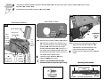
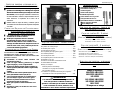
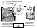
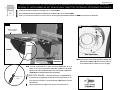
BEFORE YOU BEGIN ASSEMBLING
YOUR NEW QUALITY COLEMAN
GAS
BARBECUE GRILL:
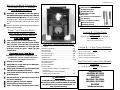
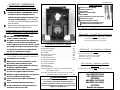
Ö
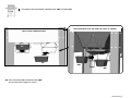
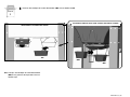
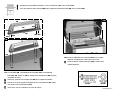
FOR EASE OF ASSEMBLY, leave the grill on
the inside bottom foam packing tray until the
wheels have been attached. (See representative
example at right). Remove the outside foam from
the right and left sides of the frame base at this
time.
Ö
Remove all cartons located on top of the barbecue
grill base and set aside.
ONE CARTON- L.P. GAS CYLINDER
CARTON B - 2 SIDE TABLE
ASSEMBLIES
(FOR
MODELS WITHOUT SIDE BURNER)
ONE RIGHT SIDE TABLE ASSEMBLY
ONE LEFT SIDE TABLE ASSEMBLY
C
ARTON B - 1 SIDE TABLE ASSEMBLY
(FOR MODELS WITH SIDE BURNER)
O
NE SIDE BURNER GRID . . . . . . . . . . . . . . . . . . . . . . . . .(41)
ONE RIGHT SIDE TABLE ASSEMBLY
O
NE LEFT SIDE BURNER ASSEMBLY
One bag Assorted assembly hardware
ONE CARTON-COLEMAN SIDE BURNER
ASSEMBLY
(FOR MODELS WITH SIDE BURNER)
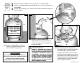
ST
ART THE COOKING GRIDS
SEASONING P
ROCESS BEFORE
ASSEMBLING
YOUR GRILL!
C
AST
I
RON
G
RIDS
Ö
Cast Iron grids are on select models only.
Ö
Your cast iron grids may have some rusting.
This is normal. To remove the rust, scour the
rusty areas with steelwool, i.e. SOS pad, until
all traces of rust are gone. Wash, dry and
season grids.
S
EASONING
C
AST
I
RON
G
RIDS
SEASONING IS THE PROCESS OF ALLOWING OIL TO BE
ABSORBED INTO THE IRON, CREATING A NON-STICK,
RUSTPROOF FINISH
. HERE’S HOW TO DO IT:
Ö
Preheat Oven to 350ºF.
Ö
Wash with hot, soapy water and a stiff brush.
Rinse and dry completely.
Ö
Oil the grids (all surfaces, top and bottom) with
MELTED solid vegetable shortening.
Ö
Turn upside down on the top rack of a 350ºF
pre-heated oven.
Ö
Put aluminum foil on the bottom rack to catch
any excess drippings.
Ö
Bake the grids for one hour at 350ºF.
Ö
Let the grid cool slowly in the oven.
Ö
Store, uncovered, in a dry place when cooled.
Tools Needed
Ö
#20 6-Lobe Screwdriver (Included)
Ö
#2 Phillips Screwdriver
Ö
An adjustable wrench
Ö
9-Volt Battery (Included)
Optional Tools
Ö
7/16" and 5/16" Box End Wrenches
Ö
7/16" Nut Driver
Ö
Electric or Cordless Screwdriver
Ö
#20 6-Lobe driver bit
Ö
#2 Phillips driver bit
Engineering Code
LD113332/LD113312
LE113332/LE113312
LE113333
LD113342
*
/LD113322
*
LE113342
*
/LE113322
*
LE113343*
*Cylinder not included
WARNING:
Combustion by-products produced when using
this product contain chemicals known to the State
of California to cause cancer, birth defects, or
other reproductive harm.

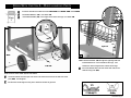
1-A
11412013FX (Pg. 3)
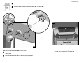
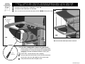
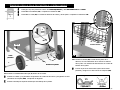
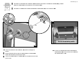
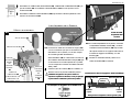
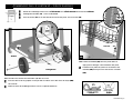
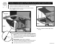
1-A. Insert the AXLE PINS (3) into the wheels.
Ö
Insert the wheels and axle pins into each side of the base and secure with two clevis
pins (WN). See diagram.
Ö
Remove the remaining foam tray from under the barbecue grill now.
WN
WN
WN
3
3
Left end
Back
16
Label
16
3
(2) Qty.
Hardware shown actual size
Ö
Remove outside foam ONLY from the LEFT SIDE and RIGHT SIDE of the BASE.
Ö
Assemble WHEELS (16). See detail 1-A.
Ö
Assemble BASKET (22) on the right end of base and legs. See detail 1-B.
Step
1
BEGIN WITH CARTON A - MISCELLANEOUS PARTS
1-B. Feed the BASKET (22) through the right legs with the
basket extensions on the outside of the legs. The
extensions will rest against the outside of the legs.
Ö
Place the Basket feet over the caster bolt and secure
with two wing nuts (DZ).
1-B
(2) Qty.
22
DZ
DZ
Right end
Back View

11412013FX (Pg. 4)
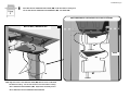
49
49
48
48
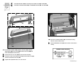
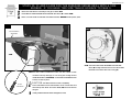
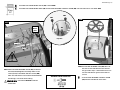
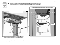
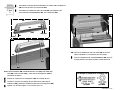
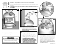
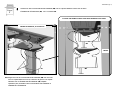
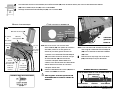
2-A. Align the holes in the GREASE PAN (48) with the holes underneath
the Bottom casting. Secure the Grease Pan to the bottom casting
with a GREASE PAN HANGER (49). Repeat the assembly for the
other GREASE PAN and GREASE PAN HANGER
BACK OF GRILL, UNDERNEATH VIEW
2-A
49
49
48
48
FRONT
VIEW SHOWN WITHOUT THE SIDE PANEL FOR CLARITY OF ASSEMBLY
Ö
Assemble the two GREASE DRIP PANS (48) under the bottom casting and
secure with the two GREASE PAN HANGERS (49). See detail 2-A.
Step
2

11412013FX (Pg. 5)
Step
3
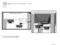
3-A. Place two DISPOSABLE GREASE PANS (48a)
into the Grease Pan Hangers as shown.
48a
48a
BACK OF G
RILL UNDERNEATH VIEW
3-A
48a
48a
VIEW SHOWN WITHOUT THE SIDE PANEL FOR CLARITY OF ASSEMBLY
Ö
Assemble the two DISPOSABLE GREASE PANS (48a). See detail 3-A.

11412013FX (Pg. 6)
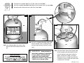
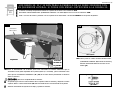
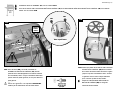
4-A. Place CONTROL KNOBS (32) on valve stems.
Ö
Insert MEAT PROBE RECEPTACLE (57a) into the right side of the
control panel.
Ö
Place the MEAT PROBE (57) into the meat probe receptable.
4-B. Place the PERFORATED STAINLESS TENT (62) in
the slots of the PORCELAIN “I” TENT (61).
4-A
32
57
57a
32
62
4-B
Ö
Assemble CONTROL KNOBS (32), MEAT PROBE RECEPTACLE (57a) and MEAT PROBE (57) in detail 4-A.
Ö
Assemble PERFORATED STAINLESS TENT (62). See detail 4-B.
Step
4
61
Front of Grill

11412013FX (Pg. 7)
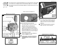
5-A. The FRONT HANDLE (58), HANDLE SPACER (60), HANDLE
INSULATOR (59), four screws (DT) and four hex nuts (AO) are
PRE-ASSEMBLED at the factory.
Ö
Remove the four hex nuts (AO) from the Handle assembly.
Ö
Insert the screws in the Handle assembly into the GRILL LID (55)
and secure with four hex nuts (AO).
Ö
Tighten with adjustable wrench or 7/16” wrench.
5-B. Place the COOKING GRIDS (63) in the Bottom casting
with the smooth surface down.
Ö
Set the WARMING RACK (65) near the back of the bottom
casting.
65
63
63
5-B
Ö
Assemble FRONT HANDLE Assembly to the GRILL LID (55) in detail 5-A.
Ö
Assemble COOKING GRIDS (63) and WARMING RACK (65). See detail 5-B.
Step
5
5-A
AO
55
AO
AO
DT
58
60
59
AO
AO
AO
DT
Hardware shown actual size
(4) Qty.
(4) Qty.

11412013FX (Pg. 8)
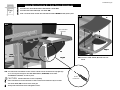
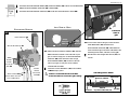
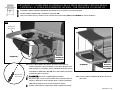
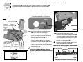
6-A. Use the 6-lobe screwdriver to back out the outside screws located in the top right legs
(2 or 3 turns) just enough for the SIDE BRACKETS (11 and 13) on the PRE-
ASSEMBLED sidetable, to slide in place.
CAUTION: DO NOT Remove screws completely.
Ö
Place the bottom slot of the brackets on the screws first and then the top slot. Note:
The TOOL BAR (12) faces the front of the grill.
Ö
Gently slide the Bracket down and tighten screws.
Ö
Assemble Pre-Assembled RIGHT SIDETABLE in detail 6-A.
Ö
Assemble the SIDE TABLE (9). See detail 6-B.
Ö
Note: Use both hands and lift with side table brackets. NEVER lift with plastic parts.
6-B. Place the SIDE TABLE (9) inside the side
frame.
Step
6
BEGIN WITH CARTON B - SIDE TABLE ASSEMBLIES
6-A
Grill
Front
PRE- ASSEMBLED
SIDETABLE
Right
11
12
13
Right
9
6-B
6-LOBE
SCREWDRIVER

11412013FX (Pg. 9)
STEPS 7 AND 8 ARE FOR THE 2000/3000 SERIES GRILL WITH TWO SIDE
TABLES. IF YOU HAVE A SIDE BURNER CONTINUE ON TO PAGE 12.
Ö
Assemble Pre-Assembled LEFT SIDETABLE in detail 7-A.
Ö
Assemble the SIDE TABLE (9). See detail 7-B.
Ö
Note: Use both hands and lift with side table brackets. NEVER lift with plastic parts.
Step
7
7-A. If you have a SIDEBURNER continue on to page 13 now.
Use the 6-lobe screwdriver to back out the outside screws located
in the top left legs (2 or 3 turns) just enough for the SIDE BRACKETS
(11 and 13) on the PRE-ASSEMBLED sidetable, to slide in place.
CAUTION: DO NOT Remove screws completely.
Ö
Place the bottom slot of the brackets on the screws first and then the
top slot. Note: The TOOL BAR (12) faces the front of the grill.
Ö
Gently slide the Bracket down and tighten screws.
7-B. Place the SIDE TABLE (9) inside the side frame.
7-A
7-B
Left
PRE- ASSEMBLED
SIDETABLE
Left
9
11
13
Grill
Front
Grill
Front
12
6-LOBE
SCREWDRIVER

11412013FX (Pg. 10)
8-A. Attach the black SWITCH WIRES (26), with the
red connecters located on the left side of your
grill, to the two large pins on the ELECTRONIC
MODULE (28). Then attach the two orange
ELECTRODE WIRES (29) located on the left
side of your grill, to the pins on the module
marked 1MB and 2MB.
Ö
Insert the 9-VOLT BATTERY (30) in the module,
it MUST snap in place.
Caution: Insure that the wires DO NOT
touch hot surfaces such as the grill casting.
LEFT S
IDE OF GRILL
ELECTRONIC
MODULE
M
AIN
BURNER
ORANGE
ELECTRODE
WIRE 29
M
AIN
BURNER
ORANGE
ELECTRODE
WIRE
29
S
WITCH WIRES 26
(
BLACK WIRES WITH RED
FLAG CONNECTERS)
9-VOLT
BATTERY
30
ELECTRONIC MODULE 28
8-A
1MB
1SB
2MB
2SB
8-B. On the LEFT side of the grill, locate the front
SIDE BRACKET (13) and attach the
ELECTRONIC MODULE (28) underneath the
front bracket flange in the holes indicated in the
Mounting Holes detail, with two screws (JS).
Ö
Bundle extra wire length with wire tie (LA) not
shown.
(2) Qty.
Hardware shown actual size
8-B
28
13
JS
JS
1MB
1SB
1SB
2MB
Side Frame
Side Frame
Electronic Module
Tool Bar
Tool Bar
Inside
Outside
Top View of Bracket (13)
Mounting Holes Detail
Ö
Assemble the ELECTRODE WIRES (29), SWITCH WIRES (26) and the 9-VOLT BATTERY
(30) to the ELECTRONIC MODULE (28) in details 8-A.
Ö
Assemble the ELECTRONIC MODULE (28) under the Left Side Table in detail 8-B.
Step
8
Orange
Electrode
Wires (29)
Black
Switch
Wires (26)
Left front
side of
grill

79
Outlet
Valve
Engineering Code
LD113342
*
/LD113322
*
LE113342
*
/LE113322
*
LE113343*
*Cylinder not included
11412013FX (Pg. 11)
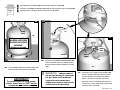
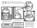
Ö
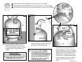
Assemble the CYLINDER (79) to the Cylinder caddy. See detail 9-A.
Ö
Place the CYLINDER RETAINER WIRE (77) over the Cylinder Collar. See detail 9-B.
Ö
Attaching TYPE 1 fitting to the fuel outlet valve in detail 9-C
Step
9
9-A Set CYLINDER (79) in the cylinder caddy with
the outlet valve facing the front of the grill.
9-A
9-C
79
27
Outlet
Valve
TYPE 1
Nipple
IMPORTANT!
TO ENSURE PROPER GAS FLOW, BURNER
CONTROL VALVES MUST
BE “OFF” BEFORE
OPENING THE GAS CYLINDER VALVE.
9-C Insert the TYPE 1 nipple of the regulator (27)
into the cylinder’s fuel valve outlet as shown.
Turn the regulator hand wheel clockwise to
tighten. No tools are needed. The Hand
wheel will come to a complete stop when the
connection is secure and gas will not flow until
a positive seal is achieved.
WARNING: During assembly of
grill and when attaching or replacing the
L.P. gas cylinder, insure that the gas
supply hose is free of kinks and/or
damage and is at least 3” away from hot
surfaces such as the grill casting.
9-B Place the CYLINDER RETAINER WIRE (77)
over the Cylinder collar, by rotating the wire
from the original position toward the cylinder
collar.
Left end
77
9-B
77

11412013FX (Pg. 12)
10-A.Use the 6-lobe screwdriver to back out the outside screws
located in the top left legs (2 or 3 turns) just enough for the
SIDE BRACKETS (11 and 13) on the PRE-ASSEMBLED side
burner, to slide in place.
CAUTION: DO NOT Remove screws completely.
Ö
Place the bottom slot of the brackets on the screws first and
then the top slot. Note: The TOOL BAR (12) faces the front of
the grill.
Ö
Gently slide the Bracket down and tighten screws.
10-B
10-B.Thread the blue SIDE BURNER ELECTRODE
wires (8) through the Base and secure the Double
electrode to the base with one screw (JS).
JS
8
Ö
Attach the Side Burner assembly to the grill in detail 10-A.
Ö
Assemble the SIDE BURNER ELECTRODE with wires (8) in detail 10-B.
Ö
Note: Use both hands and lift with side table brackets. NEVER lift with plastic parts.
Hardware shown actual size
(1) Qty.
Top View
10-A
Left
PRE
- ASSEMBLED
SIDEBURNER
Grill
Front
12
Step
10
STEPS 10, 11 AND 12 ARE FOR THE 2000/3000 SERIES GRILL WITH A SIDE
BURNER. IF YOU HAVE TWO SIDE TABLES GO BACK TO PAGE 9.
6-LOBE
SCREWDRIVER

11412013FX (Pg. 13)
11-A. Attach the black SWITCH WIRES (26), with the
red connecters located on the left side of your
grill, to the two large pins on the ELECTRONIC
MODULE (28). Then attach the two orange
lead ELECTRODE WIRES (29) to the pins on
the module marked 1MB and 2MB and the two
blue Side Burner Electrode wires to the pins on
the module marked 1SB and 2SB.
Ö
Insert the 9-VOLT BATTERY (30) in the
module, it MUST snap in place.
Caution: Insure that the wires DO NOT
touch hot surfaces such as the grill casting.
ELECTRONIC
MODULE
M
AIN
BURNER
ORANGE
ELECTRODE
WIRE
29
M
AIN
BURNER
ORANGE
ELECTRODE
WIRE
29
9-VOLT BATTERY 30
11-A
1MB
1SB
2MB
2SB
BLUE
S
IDE
BURNER
ELECTRODE
WIRES
Ö
Assemble the IGNITER WIRES (lead ELECTRODE WIRES (29) and Side burner wires), SWITCH WIRES (26) and the 9-VOLT
BATTERY (30) in details 11-A.
Ö
Assemble the ELECTRONIC MODULE (28) in detail 11-B.
Step
11
LEFT S
IDE OF GRILL
(2) Qty.
Hardware shown actual size
Orange
Electrode
Wires (29)
Black
Switch
Wires (26)
11-B
28
13
JS
1MB
1SB
2MB
2SB
JS
11-B.Locate the front SIDE BRACKET (13) and
attach the ELECTRONIC MODULE (28)
underneath the front bracket flange in the
holes indicated with two screws (JS).
Ö
Bundle extra wire length with wire tie (LA) not
shown.
ELECTRONIC
M
ODULE
28
S
WITCH WIRES
26
(
BLACK WIRES
WITH RED FLAG
CONNECTERS
)
Left front
side of
grill
Side Frame
Side Frame
Electronic Module
Tool Bar
Tool Bar
Inside
Outside
Top View of Bracket (13)
Mounting Holes Detail

11412013FX (Pg. 14)
Ö
Assemble the SIDE BURNER VALVE (27) in detail 12-A.
Ö
Assemble the SIDE BURNER GRID (41) and the SIDE BURNER CONTROL KNOB (40) onto the Side burner. See detail 12-B.
Hardware shown actual size
(2) Qty.
12-A. Attach the SIDE BURNER VALVE (27) (located on
the Hose/Valve/Regulator assembly attach to the
control panel) to the BASE with two screws (HA).
Note: the Side burner hose must be thread between
the left legs, not in front of the left leg.
WARNING
: The orifice must be inside the
venturi tube.
Step
12
12-B. Set the SIDE BURNER GRID (41) tabs into
the slots on the Side Burner base and turn
the grid until it stops. Note: Before each use
turn the Side Burner grid to insure that it is
secure.
Ö
Push the SIDE BURNER CONTROL KNOB
(40) onto the Side Burner Valve stem.
12-B
41
40
HA
HA
Side
Burner
Valve
Top View
Venturi tube
Orifice
12-A
27

11412013FX (Pg. 15)
13-C Insert the TYPE 1 nipple of the regulator (27)
into the cylinder’s fuel valve outlet as shown.
Turn the regulator hand wheel clockwise to
tighten. No tools are needed. The Hand
wheel will come to a complete stop when the
connection is secure and gas will not flow until
a positive seal is achieved.
WARNING: During assembly of
grill and when attaching or replacing the
L.P. gas cylinder, insure that the gas
supply hose is free of kinks and/or
damage and is at least 3” away from hot
surfaces such as the grill casting.
13-C
13-A Set CYLINDER (79) in the cylinder caddy
with the outlet valve facing the front of the
grill.
13-B Place the CYLINDER RETAINER WIRE (77)
over the Cylinder collar, by rotating the wire
from the original position toward the cylinder
collar.
13-A
79
79
Ö
Assemble the CYLINDER (79) to the Cylinder caddy. See detail 13-A.
Ö
Place the CYLINDER RETAINER WIRE (77) over the Cylinder Collar. See detail 13-B.
Ö
Attaching TYPE 1 fitting to the fuel outlet valve in detail 13-C.
Step
13
Outlet
Valve
Outlet
Valve
27
Type 1
Nipple
IMPORT
ANT!
T
O ENSURE PROPER GAS FLOW, BURNER
CONTROL VALVES MUST
BE “OFF” BEFORE
OPENING THE GAS CYLINDER VALVE.
Engineering Code
LD113342
*
/LD113322
*
LE113342
*
/LE113322
*
LE113343*
*Cylinder not included
Left end
77
77
13-B

11412013FX (Pg. 16)
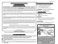
COLEMAN GAS BARBECUE GRILL WARRANTY
CASTINGS - LIMITED LIFETIME
BURNER - LIMITED FIVE (5) YEARS
OTHER PARTS
- LIMITED ONE (1) YEAR
The Coleman Company, Inc. (“Coleman”) warrants that for the period that you own this product, it will be free from defects in
material and workmanship. This warranty applies to the following parts for the following time periods: the castings are
warranted for LIFETIME against burn through; the burner is warranted for five (5) years; and other parts are warranted for one
(1) year, except the propane cylinder and paint finish. We DO NOT WARRANT in any way the propane cylinder (see label
on cylinder for cylinder manufacturer’s warranty) or the paint finish of the product. Coleman, at its option, will repair or replace
this product or any component of the product found to be defective during the warranty period. Replacement will be made
with a new or remanufactured product or component. If the product is no longer available, replacement may be made with a
similar product of equal or greater value. This is your exclusive warranty.
This warranty is valid for the original retail purchaser from the date of initial retail purchase and is not transferable. Keep the
original sales receipt. Proof of purchase is required to obtain warranty performance. Coleman dealers, service centers, or
retail stores selling Coleman products do not have the right to alter, modify or any way change the terms and conditions of this
warranty.
This warranty does not cover normal wear of parts or damage resulting from any of the following: negligent use or misuse of
the product, use on improper voltage or current, use contrary to the operating instructions, disassembly, repair or alteration by
anyone other than Coleman or an authorized service center. Further, the warranty does not cover Acts of God, such as fire,
flood, hurricanes and tornadoes.
Coleman shall not be liable for any incidental or consequential damages caused by the breach of any express or implied
warranty. Except to the extent prohibited by applicable law, any implied warranty of merchantability or fitness for a particular
purpose is limited in duration to the duration of the above warranty. Some states, provinces or jurisdictions do not allow the
exclusion or limitation of incidental or consequential damages or limitations on how long an implied warranty lasts, so the
above limitations or exclusion may not apply to you. This warranty gives you specific legal rights, and you may also have other
rights that vary from state to state or province to province.
DO NOT RETURN THIS PRODUCT TO THE PLACE OF PURCHASE.
Take the product to an authorized Coleman service center. You can find the nearest authorized Coleman service center by
calling 1-800-356-3612. If a service center is not conveniently located, you may call the same number for instructions on
shipping the product to the Coleman Company, Inc. You may also call the same number if you have any questions concerning
this warranty.
NOT VALID IN MEXICO.
For WARRANTY, SERVICE and PARTS
Locate your model number and serial number on the label found on the back of your grill base.
C
ARE OF
S
TAINLESS
S
TEEL
P
ARTS
Ö
BEFORE cleaning any part of the grill, allow the grill to cool down completely.
Ö
Clean the grill with any multipurpose metal polish or stainless polish, low in abrasive and with no phosphorus
ingredients. (Read cleaner labels for suggested uses and directions on proper use of the cleaner.)
Ö
Use a soft cloth or sponge to prevent scratches and marring of the stainless steel surfaces.
Ö
NEVER USE OVEN CLEANERS.
Ö
To protect the integrity of your grill against the effects of the environment, use a grill cover when the grill is not
in use.
Ö
Failure to comply with the owner’s USE & CARE MANUAL INSTRUCTIONS & ASSEMBLY INSTRUCTIONS can void
right of warranty.
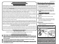
Leak test gas supply connections outdoors as
indicated by arrows.
CONSUMER NOTICE
These assembly instructions are designed for
more than one model of barbecue grill. Features
shown MAY NOT be in your grill and will not be
provided by this company or at the place of
purchase for your grill.
WARNING! The edges of sheet metal parts can
cause injury if not handled with care.
USE EXTREME CAUTION!
WARNING! WHEN LEAK TESTING:
DO NOT smoke.
DO NOT use fire to test for leaks.
DANGER:
NEVER store a spare LP gas supply cylinder under the
grill body nor inside grill enclosure to avoid the possibility
of an explosion. Refer to the Use and Care manual.
IMPORTANT:
Be sure to tighten up all hardware (screws, nuts, bolts,
etc.) at least once a year or each grilling season.
READ
OWNER’S USE AND CARE MANUAL:
For proper filling and purging of the cylinder
For leak testing all gas supply connections
For correct grill lighting instructions
For use and storage of the grill and cylinder
BEFORE USING YOUR GRILL

11412013FX (Pg. 17)
BUSQUE LO SIGUIENTE EN
EL INTERIOR:
Instrucciones para un ensamblaje fácil,
Información sobre la garantía,
Consejos sobre la seguridad,
Mantenimiento y limpieza.
GRILL
Coleman Company, Inc.
4101 Howard Bush Drive
Neosho, Missouri 64850
Página en Internet:
www.bbqhq.com
1-800-356-3612
BUSQUE EN EL PAGINA 20
PARA HALLAR:
Procedimientos de curación del metal
de la parrilla antes de cocinar.
Procedimientos para guardar
correctamente
las rejillas de fierro moldeado.
Pila de 9 volts Incluye
INSTRUCCIONES
DE ENSAMBLAJE
PARA LAS
PARRILLAS DE
GAS DE LA SERIE
2000 Y 3000
ADVERTENCIA:
LOS BORDES DE LA HOJA DE METAL PUEDEN CAUSAR
LESIONES SI NO SON MANEJADOS CON CUIDADO
.
¡TENGA EXTREMA PRECAUCION!
¡IMPORTANTE!
PARA ASEGURAR UN CORRECTIO FLUIDO DE GAS, LAS
VALVULAS DE CONTROL DE LOS QUEMADORES DEBERAN
ESTAR EN LA POSICION
“OFF” (APAGADO)
ANTES DE ABRIR LA VALVULA DE GAS DEL TANQUE.

11412013FX (Pg. 18)
Dos ruedas . . . . . . . . . . . . . . . . . . . . . . . . . . . . . . . . . . . . (16)
Dos perillas de control principa . . . . . . . . . . . . . . . . . . . . . (32)
Un alambre para la grasa . . . . . . . . . . . . . . . . . . . . . . . . ..(49)
Una bandeja para la grasa . . . . . . . . . . . . . . . . . . . . . . . .(49a)
Dos recipientes para que gotee la grasa . . . . . . . . . . . . . . (48)
Una cubierta perforada . . . . . . . . . . . . . . . . . . . . . . . . . . . (62)
Una sonda para la carne . . . . . . . . . . . . . . . . . . . . . . . . . ..(57)
Un receptáculo para la sonda de la carne . . . . . . . . . . . . .(57a)
Ensamblaje con un asa
Una bolsa con manuales e información escrita
Un destornillador Torx 6-lobe
Bolsa(s) con herrajes:
Diversas piezas de ensamblaje.
Una bolsa con un juego de encendedor
Dos pasadores del eje . . . . . . . . . . . . . . . . . . . . . . . . . . (3)
Los modelos con quemador lateral incluyen lo siguiente:
Una perrilla de control del quemador lateral. . . . . . . . . .(40)
CAJA DE CARTON A - VARIAS PIEZAS
ANTES DE EMPEZAR A ENSAMBLAR SU
NUEVA PARRILLA DE GAS DE ALTA CALIDAD:
Ö
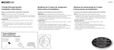
PARA FACILITAR EL ENSAMBLAJE, dejar la
parrilla en la bandeja de embalaje de espuma
del fondo interior hasta que se hayan colocado
las ruedas. (Vea un ejemplo mostrado a la derecha).
En este momento, extraer la espuma exterior de los
lados derechos e izquierdos de la base de la
estructura.
Ö
Extraer todas las cajas de cartón y cartones que se
encuentran encima de la base de la parrilla coloquelas
a un lado.
UNA CAJA DE CARTON - TANQUE DE
GAS
PROPANO LICUADO
C
AJA DE CARTON
B - 2 MESAS
LATERALES ARMABLES
(P
ARA LOS MODELOS SIN
EL QUEMADOR LATERAL)
U
N MONTAJE DE MESA LATERAL DERECHA
U
N MONTAJE DE MESA LATERAL IZQUIERDA
C
AJA
DE CAR
TON B - 1 MONTAJE
DE MESA LATERAL
(PARA LOS MODELOS CON EL QUEMADOR LATERAL)
UNA PARRILLA DEL QUEMADOR LATERAL . . . . . . . . . . . . . ..(41)
U
N MONTAJE DE MESA LATERAL DERECHA
UN MONTAJE DEL QUEMADOR LATERAL IZQUIERDO
UNA BOLSA - DIVERSOS HERRAJES DE ENSAMBLAJE
UNA CAJA DE CARTON - QUEMADOR
LATERAL COLEMAN ENSAMBLAJE
(P
ARA LOS MODELOS CON
EL QUEMADOR LATERAL)
CURTIR LAS REJILLAS DE COCCIÓN ANTES
DE ENSAMBLAR
LA PARRILLA !
PARRILLAS
DE FIERRO MOLDEADO
Ö
Las parrillas de fierro moldeado tan solo se
encuentran en modelos selectos.
Ö
Puede que sus parrillas de fierro moldeado
presenten algo de óxido. Esto es normal. Para
eliminar el óxido, tallar las zonas oxidadas con un
estropajo de metal hasta hacer desaparecer todos los
restos de óxido. Lavar, secar y realizar el proceso de
curación del metal de las parrillas.
C
URACION DE
LAS PARRILLAS DE FIERRO
MOLDEADA
LA CURACION ES EL PROCESO DE PERMITIR QUE EL ACEITE SEA
ABSORBIDO POR EL FIERRO
, CREANO ASI UN ACABADO
ANTIADHERENTE Y A PRUEBA DE OXIDO
. AQUI EXPLICAMOS COMO
REALIZAR EL PROCESO
:
Ö
Precalentar el Horno hasta alcanzar una
temperatura de 350_F
Ö
Lavar con agua caliente y jabonosa y un cepillo
rígido. Enjuagar y secar completamente.
Ö
Engrase las parrillas (la parte superior e inferior de
toda la superficie) utilizando manteca vegetal sólida,
previamente
fundida.
Ö
Colocarla al revés sobre la parrilla superior de un
horno precalentado a 350 ºF (176,66 ºC).
Ö
Colocar papel de aluminio en la rejilla inferior,
para así atrapar el goteo de excesivo grasa .
Ö
Hornear las parillas durante una hora a una
temperatura de 350 ºF (176,66 ºC).
Ö
Dejar que la parilla se enfríe lentamente en el
horno.
Ö
Guardar sin cubrir, en un sitio seco una vez la
rejilla esté fría.
Herramientas Necesarias
Ö
Destornillador Nº 20 6-Lobe (Incluye)
Ö
Destornillador Phillips Nº 2
Ö
Una llave inglesa
Ö
Pila de 9 volts (Incluye)
Herramientas Opcionales
Ö
Llaves de tubo de 1 cm y 8 mm
Ö
Llave para tuercas de 1 cm
Ö
Destornillador eléctrico o inalámbrico
Ö
Broca Torx Nº T-20 6-lobe
Ö
Broca Phillips Nº 2
Código de Ingeniería
LD113332/LD113312
LE113332/LE113312
LE113333
LD113342
*
/LD113322
*
LE113342
*
/LE113322
*
LE113343*
* El tanque no se incluye
ADVERTENCIA:
Los derivados de la combustión generados al
usar este producto contienen sustancias
químicas conocidas por el Estado de California
como causantes de cáncer, defectos en el
nacimiento u otros daños al sistema reproductor.

WN
WN
WN
3
3
16
16
3
1-B
22
DZ
DZ
11412013FX (Pg. 19)
1-A. Insertar los PASADORES DEL EJE (3) dentro de las ruedas.
Ö
Insertar las ruedas y los pasadores del eje dentro de cada lado de la base y asegurelas con dos
pasadores de horquilla (WN). Comprobar el diagrama.
Ö
Extraer la bandeja de espuma restante que esta debajo de la parrilla.
Extremo izquierdo
Parte
posterior
Etiqueta
(2) Cdad.
Los herrajes se muestran en su tamaño real
Ö
Extraiga la espuma protectora exterior del LADO IZQUIERDO y del LADO DERECHO de la BASE.
Ö
Ensamblar las RUEDAS (16). Comprobar la ilustración 1-A.
Ö
Ensamblar la cesta (22) en el extremo derecho de la base y de las patas. Comprobar la ilustración 1-B.
Paso
1
EMPIECE CON LA CAJA DE CARTON A - PIEZAS VARIAS
1-B. Insertar la CESTA (22) a través de las patas de la
derecha, con las extensiones de la cesta en el exterior
de las patas. Las extensiones descansarán en contra del
exterior de las patas.
Ö
Colocar el pie de la cesta sobre el perno de la rueda
pivotante y asegurar con dos tuercas de mariposa (DZ).
(2) Cdad.
Extremo derecho
Vista posteriror

11412013FX (Pg. 20)
Paso
2
49
49
48
48
VISTA INFERIOR Y POSTERIOR DEL ASADOR
2-A
49
49
48
48
FRONTAL
LA IMAGEN SE MUESTRA SIN EL PANEL LATERAL PARA MAYOR CLARIDAD
2-A. Alinee los agujeros en la BANDEJA DE ACEITE (48) con los
agujeros que se encuentran bajo el casco inferior. Sujete las
bandejas de aceite al casco inferior con los GANCHOS DE
SUSPENSIÓN (49). Repita el operación con la otra BANDEJA DE
ACEITE y BANDEJA RECOLECTORA DE ACEITE.
Ö
Arme las dos BANDEJAS RECOLECTORAS DE ACEITE (48) que se encuentran bajo el casco
inferior y asegúrelas con los dos GANCHOS DE SUSPENSIÓN (49). Vea los detalles en 2-A.
La page est en cours de chargement...
La page est en cours de chargement...
La page est en cours de chargement...
La page est en cours de chargement...
La page est en cours de chargement...
La page est en cours de chargement...
La page est en cours de chargement...
La page est en cours de chargement...
La page est en cours de chargement...
La page est en cours de chargement...
La page est en cours de chargement...
La page est en cours de chargement...
La page est en cours de chargement...
La page est en cours de chargement...
La page est en cours de chargement...
La page est en cours de chargement...
La page est en cours de chargement...
La page est en cours de chargement...
La page est en cours de chargement...
La page est en cours de chargement...
La page est en cours de chargement...
La page est en cours de chargement...
La page est en cours de chargement...
La page est en cours de chargement...
La page est en cours de chargement...
La page est en cours de chargement...
La page est en cours de chargement...
La page est en cours de chargement...
-
 1
1
-
 2
2
-
 3
3
-
 4
4
-
 5
5
-
 6
6
-
 7
7
-
 8
8
-
 9
9
-
 10
10
-
 11
11
-
 12
12
-
 13
13
-
 14
14
-
 15
15
-
 16
16
-
 17
17
-
 18
18
-
 19
19
-
 20
20
-
 21
21
-
 22
22
-
 23
23
-
 24
24
-
 25
25
-
 26
26
-
 27
27
-
 28
28
-
 29
29
-
 30
30
-
 31
31
-
 32
32
-
 33
33
-
 34
34
-
 35
35
-
 36
36
-
 37
37
-
 38
38
-
 39
39
-
 40
40
-
 41
41
-
 42
42
-
 43
43
-
 44
44
-
 45
45
-
 46
46
-
 47
47
-
 48
48


Coleman 2000 & 3000 Series Le manuel du propriétaire
- Catégorie
- Barbecues
- Taper
- Le manuel du propriétaire
dans d''autres langues
Documents connexes
Autres documents
-
Sunbeam SD113232 Manuel utilisateur
-
-
 Closet Maid 8178 Manuel utilisateur
-
-
Closet Maid 6-Cube Manuel utilisateur
-
-
Falcon FN3411 Le manuel du propriétaire
-
-
Fire Magic Echelon BLACK Diamond Built-In Grill Manuel utilisateur
-
Fire Magic A660I6LANW Guide d'installation
