Gigabyte AORUS MODEL X 12th Le manuel du propriétaire
- Taper
- Le manuel du propriétaire

To reduce the impacts on global warming, the packaging materials of this product
are recyclable and reusable. GIGABYTE works with you to protect the environment.
For more product details, please visit GIGABYTE's website.
AORUS MODEL X
GAMING DESKTOP PC
(AMXI9N8A-2171)
User's Manual
Rev. 1001

Copyright
© 2021 GIGA-BYTE TECHNOLOGY CO., LTD. All rights reserved.
The trademarks mentioned in this manual are legally registered to their respective owners.
Disclaimer
Information in this manual is protected by copyright laws and is the property of GIGABYTE.
Changes to the specications and features in this manual may be made by GIGABYTE without
prior notice. No part of this manual may be reproduced, copied, translated, transmitted, or
published in any form or by any means without GIGABYTE's prior written permission.
Documentation Classications
In order to assist in the use of this product, GIGABYTE provides the following types of
documentations:
For quick set-up of the product, read the Quick Start Guide included with the product.
For detailed product information, carefully read the User's Manual.
For product-related information, check on our website at: https://www.gigabyte.com

- 3 -
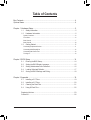
Table of Contents
Box Contents ...................................................................................................................4
Optional Items .................................................................................................................4
Chapter 1 Hardware Setup .............................................................................................5
1-1 Safety Information ............................................................................................ 5
1-2 Hardware Information ....................................................................................... 6
System Overview ....................................................................................................................6
Front View ..............................................................................................................................6
Back View-A ...........................................................................................................................7
Back View-B .........................................................................................................................10
1-3 Getting Started ............................................................................................... 11
Connecting Peripheral Devices ............................................................................................11
Connecting Mini-DisplayPort ...............................................................................................12
Connecting the Power Cord .................................................................................................13
Turning on ............................................................................................................................13
Chapter 2 BIOS Setup ..................................................................................................14
2-1 Entering the BIOS Setup ................................................................................ 14
2-2 Setting the BIOS Display Language ............................................................... 15
2-3 Setting Administrator/User Password ............................................................. 16
2-4 Loading Optimized Defaults ........................................................................... 17
2-5 Saving the BIOS Settings and Exiting ............................................................ 18
Chapter 3 Appendix ......................................................................................................19
3-1 Installing a 2.5" Drive ..................................................................................... 19
3-2 Installing a 3.5" Drive ..................................................................................... 20
3-3 Cleaning the Dust Filter .................................................................................. 21
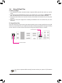
3-4 Using Q-Flash Plus ........................................................................................ 22
Regulatory Notices .................................................................................................... 23
Contact Us ................................................................................................................ 26

Box Contents
5AORUS MODEL X GAMING DESKTOP PC
5Quick Start Guide
5AC power cord
5Antennas
52.5" drive screws
5Two Mini-DisplayPort cables
* The box contents above are for reference only and the actual items shall depend on the product package you obtain.
The box contents are subject to change without notice.
Optional Items
Glass side panel
- 4 -

Chapter 1 Hardware Setup
1-1 Safety Information
•Before connecting to the power outlet, make sure that the voltage rating of the power cable is
compatible with the power specication in the country where you are located.
•The power cord plug must be connected to a properly wired and grounded power outlet.
•Be sure that the power outlet you plug the power cord into is easily accessible and located
as close to the equipment operator as possible. When you need to disconnect power to the
equipment, be sure to unplug the power cord from the electrical outlet.
•Do not touch the plug with wet hands, otherwise easily cause electric shock.
•Protect the power cord from being tread upon or pinched, particularly at the plug.
•To avoid damage of internal component, do not place the product on a vibrating surface.
•Operating temperature: 5~35oC.
•Do not place the product near any heat sources such as electric radiators, heat registers,
stoves or other devices (including ampliers) that produce heat.
•The holes or openings on this product are for ventilation to ensure reliable operation of the
product and to protect it from overheating. Do not cover or block the ventilation holes with
any objects.
•Never push objects of any kind into this product through cabinet slots as they may touch
dangerous voltage points or short-out parts that could result in a re or electric shock.
•Never spill liquid of any kind onto or into the product.
•Do not use this product near water, drinks, or all types of liquids. Do not expose this apparatus
to rain, liquid or moisture. Failure to do so may result in electric shock or damage.
•This product is not water proof or oil-proof.
•Clean the equipment with a soft, dry cloth.
•The manufacturer species that the thumbscrews normally should be tightened with a
screwdriver, use of thumbscrews is not considered to compromise the basic principles of
safety associated with the Safety Standard.
•For the motherboard battery replacement, refer to the motherboard’s User Manual.
- 5 -

1-2 Hardware Infor—mation
System Overview
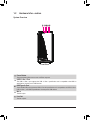
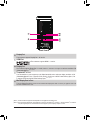
Front View
Power Button
The power button allows users to turn on/off the computer.
USB 3.2 Gen 1 Port
The USB 3.2 Gen 1 port supports the USB 3.2 Gen 1 specication and is compatible to the USB 2.0
specication. Use this port for USB devices.
USB Type-C® Port
The reversible USB port supports the USB 3.2 Gen 2x2 specication and is compatible to the USB 3.2 Gen 2,
USB 3.2 Gen 1, and USB 2.0 specication. Use this port for USB devices.
Mic In
The Mic in jack.
Line Out
The line out jack.
- 6 -

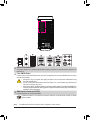
Back View-A
Q-Flash Plus Button (Note)
This button allows you to update the BIOS when the power connector is connected but the system is not
powered on.
Clear CMOS Button
Use this button to clear the CMOS values (e.g. BIOS conguration) and reset the CMOS values to factory
defaults when needed.
•Always turn off your computer and unplug the power cord from the power outlet before using
the clear CMOS button.
•Do not use the clear CMOS button when the system is on, or the system may shutdown and
data loss or damage may occur.
•After system restart, go to BIOS Setup to load factory defaults (select Load Optimized Defaults) or
manually congure the BIOS settings (please navigate to the "BIOS Setup" page of GIGABYTE's
website for more information).
SMA Antenna Connectors (2T2R)
Use this connector to connect an antenna.
Tighten the antennas to the antenna connectors and then aim the antennas correctly for better
signal reception.
(Note) To enable the Q-Flash Plus function, refer to "Chapter 3" of the manual.
- 7 -

USB 3.2 Gen 1 Port
The USB 3.2 Gen 1 port supports the USB 3.2 Gen 1 specication and is compatible to the USB 2.0
specication. Use this port for USB devices.
USB 3.2 Gen 2 Type-A Port (Red)
The USB 3.2 Gen 2 port supports the USB 3.2 Gen 2 specication and is compatible to the USB 3.2 Gen 1
and USB 2.0 specication. Use this port for USB devices.
DisplayPort
DisplayPort delivers high quality digital imaging and audio, supporting bi-directional audio transmission.
DisplayPort can support HDCP 2.3 content protection mechanisms. You can use this port to connect your
DisplayPort-supported monitor. Note: The DisplayPort Technology can support a maximum resolution of
4096x2304@60 Hz but the actual resolutions supported depend on the monitor being used.
USB Type-C® Port (with USB 3.2 Gen 2 Support)
The reversible USB port supports the USB 3.2 Gen 2 specication and is compatible to the USB 3.2 Gen 1
and USB 2.0 specication. Use this port for USB devices.
After installing the DisplayPort device, make sure to set the default sound playback device to
DisplayPort. (The item name may differ depending on your operating system.)
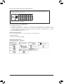
RJ-45 LAN Port
The Gigabit Ethernet LAN port provides Internet connection at up to 10 Gbps data rate. The following
describes the states of the LAN port LEDs.
USB 3.2 Gen 2 Type-A Port (Q-Flash Plus Port)
The USB 3.2 Gen 2 port supports the USB 3.2 Gen 2 specication and is compatible to the USB 3.2 Gen 1
and USB 2.0 specication. Use this port for USB devices. Before using Q-Flash Plus (Note), make sure to
insert the USB ash drive into this port rst.
USB Type-C® Port (with USB 3.2 Gen 2x2 Support)
The reversible USB port supports the USB 3.2 Gen 2x2 specication and is compatible to the USB 3.2
Gen 2, USB 3.2 Gen 1, and USB 2.0 specications. Use this port for USB devices.
Center/Subwoofer Speaker Out
Use this audio jack to connect center/subwoofer speakers.
Rear Speaker Out
Use this audio jack to connect rear speakers.
Optical S/PDIF Out Connector
This connector provides digital audio out to an external audio system that supports digital optical audio.
Before using this feature, ensure that your audio system provides an optical digital audio in connector.
Line In/Side Speaker Out
The line in jack. Use this audio jack for line in devices such as an optical drive, walkman, etc.
Line Out/Front Speaker Out
The line out jack. This jack supports audio amplifying function. For better sound quality, it is recommended
that you connect your headphone/speaker to this jack (actual effects may vary by the device being used).
Mic In/Side Speaker Out
The Mic in jack.
Speed LED Activity LED
LAN Port
Speed LED:
State Description
Green 10 Gbps data rate
Orange 5 Gbps/ 2.5 Gbps/ 1 Gbps/
100 Mbps data rate
Activity LED:
State Description
Blinking Data transmission or receiving is occurring
On No data transmission or receiving is occurring
(Note) To enable the Q-Flash Plus function, refer to "Chapter 3" of the manual.
- 8 -

•If you want to install a Side Speaker, you need to retask either the Line in or Mic in jack to be
Side Speaker out through the audio driver.
•To enable or congure the audio amplifying function for the Line out jack, please access the
Realtek Audio Console application.
Audio Jack Congurations:
Jack Headphone/2-channel 4-channel 5.1-channel 7.1-channel
Center/Subwoofer Speaker Out a a
Rear Speaker Out a a a
Line In/Side Speaker Out a
Line Out/Front Speaker Out a a a a
Mic In a
- 9 -

Back View-B
DisplayPort
The connector supports DisplayPort 1.4a version.
HDMI Port
The connector supports HDMI 2.1 version.
DisplayPort
The connector supports DisplayPort 1.4 version, HDCP 2.2, and HDR. It can support a maximum resolution of 8K
(7680x3840)@60 Hz. (Note 1) (Note 2)
Thunderbolt™ 4 Port
The Thunderbolt™ 4 ports support up to 40 Gbps bandwidth and a maximum display resolution of 8K
(7680x3840)@60 Hz. Port 1 supports 5V/3A, 9V/3A, 15V/3A, and 19V/5A Power Delivery Spec.; Port
2 supports 5V/3A and 9V/3A Power Delivery Spec
.
(Note 1) (Note 2)
Mini-DisplayPort In Port
The mini-DisplayPort allows you to
use the included Mini-DisplayPort cable to connect your graphics card to the
GC-MAPLE RIDGE add-in card.
(Note 1) Actual resolutions supported are dependent on the graphics card being used.
(Note 2) Due to hardware limitations, the DisplayPort connector, Thunderbolt™ 4 connector 1, and Thunderbolt™ 4 connector
2 require signal input from external devices and support up to two display outputs at a time.
- 10 -

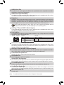
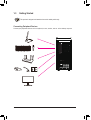
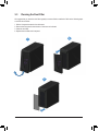
1-3 Getting Started
This product is designed and intended to be used in vertical position only.
Connecting Peripheral Devices
Connect your peripheral devices such as keyboard, mouse, monitor, and etc. to the desktop computer.
- 11 -

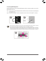
Connecting Mini-DisplayPort
Follow the steps below to use the included Mini-DisplayPort cables to connect the graphics card to the GC-
MAPLE RIDGE add-in card.
Step 1: Connect one end of the mini-DisplayPort cable to the DP IN connector and the other end to the DisplayPort
on the graphics card.
Step 2: Connect the Thunderbolt™ device's or DisplayPort monitor’s cable to the Thunderbolt™ 4 connector .
1
Thunderbolt™ or
DisplayPort
monitor cable
2
•When connecting one DisplayPort monitor, please connect the Mini-DisplayPort cable to the DP IN 1 connector,
then connect the monitor's cable to the DisplayPort connector or Thunderbolt™ 4 connector 1.
•When connecting two DisplayPort monitors, please connect one of the Mini-DisplayPort cables to the DP IN 1
connector and connect the monitor's cable to the DisplayPort connector or Thunderbolt™ 4 connector 1. Then connect
the other Mini-DisplayPort cable to the DP IN 2 connector and the monitor's cable to Thunderbolt™ 4 connector 2.
Thunderbolt™ 4 Port 2
Mini-DisplayPort In
Port 2 (DP IN 2)
DisplayPort
Thunderbolt™ 4 Port 1
Mini-DisplayPort In
Port 1 (DP IN 1)
3
- 12 -

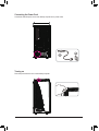
Connecting the Power Cord
Connect the included power cord to the desktop computer and a power outlet.
Turning on
Press the power button to turn on the desktop computer.
AB
- 13 -

Chapter 2 BIOS Setup
Function Keys
•Because BIOS ashing is potentially risky, if you do not encounter problems using the current version of BIOS,
it is recommended that you not ash the BIOS. To ash the BIOS, do it with caution. Inadequate BIOS ashing
may result in system malfunction.
•It is recommended that you not alter the default settings (unless you need to) to prevent system instability or other
unexpected results. Inadequately altering the settings may result in system's failure to boot. If this occurs, try to
clear the CMOS values and reset the board to default values. (Refer to the "Load Optimized Defaults" section
for how to clear the CMOS values.)
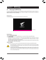
Startup Screen
The following startup Logo screen will appear when the computer boots.
Function Keys:
<DEL>: BIOS SETUP\Q-FLASH
Press the <Delete> key to enter BIOS Setup or to access the Q-Flash utility in BIOS Setup.
<F12>: BOOT MENU
Boot Menu allows you to set the rst boot device without entering BIOS Setup. In Boot Menu, use the up
arrow key <h> or the down arrow key <i> to select the rst boot device, then press <Enter> to accept.
The system will boot from the device immediately.
Note: The setting in Boot Menu is effective for one time only. After system restart, the device boot order
will still be based on BIOS Setup settings.
<END>: Q-FLASH
Press the <End> key to access the Q-Flash utility directly without having to enter BIOS Setup rst.
2-1 Entering the BIOS Setup
To access the BIOS Setup program, press the <Delete> key during the POST when the power is turned on.
When the power is turned off, the battery on the motherboard supplies the necessary power to the CMOS to
keep the conguration values in the CMOS.
- 14 -

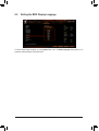
2-2 Setting the BIOS Display Language
To set the BIOS display language, go to the System Info. menu. The BIOS Language setting allows you to
select the default language used by the BIOS.
- 15 -

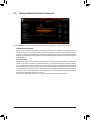
2-3 Setting Administrator/User Password
&Administrator Password
Allows you to congure an administrator password. Press <Enter> on this item, type the password, and
then press <Enter>. You will be requested to conrm the password. Type the password again and press
<Enter>. You must enter the administrator password (or user password) at system startup and when entering
BIOS Setup. Differing from the user password, the administrator password allows you to make changes to
all BIOS settings.
&User Password
Allows you to congure a user password. Press <Enter> on this item, type the password, and then press
<Enter>. You will be requested to conrm the password. Type the password again and press <Enter>.
You must enter the administrator password (or user password) at system startup and when entering BIOS
Setup. However, the user password only allows you to make changes to certain BIOS settings but not all.
To cancel the password, press <Enter> on the password item and when requested for the password, enter
the correct one rst. When prompted for a new password, press <Enter> without entering any password.
Press <Enter> again when prompted to conrm.
NOTE: Before setting the User Password, be sure to set the Administrator Password rst.
Go to the Boot menu to set the administrator password or user password for your desktop computer.
- 16 -

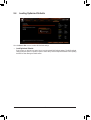
2-4 Loading Optimized Defaults
Go to the Save & Exit menu to load the BIOS default settings.
&Load Optimized Defaults
Press <Enter> on this item and select Yes to load the optimal BIOS default settings. The BIOS defaults
settings help the system to operate in optimum state. Always load the Optimized defaults after updating
the BIOS or after clearing the CMOS values.
- 17 -

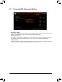
2-5 Saving the BIOS Settings and Exiting
&Save & Exit Setup
Press <Enter> on this item and select Yes. This saves the changes to the CMOS and exits the BIOS Setup
program. Select No or press <Esc> to return to the BIOS Setup Main Menu.
&Exit Without Saving
Press <Enter> on this item and select Yes. This exits the BIOS Setup without saving the changes made
in BIOS Setup to the CMOS. Select No or press <Esc> to return to the BIOS Setup Main Menu.
&Boot Override
Allows you to select a device to boot immediately. Press <Enter> on the device you select and select Yesto
conrm. Your system will restart automatically and boot from that device.
- 18 -

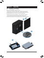
Chapter 3 Appendix
Refer to the following steps to install a 2.5" drive:
1. Remove the two screws from the side panel. Then pull out the side panel.
2. Release the thumb screw from the 2.5" drive bracket to take out the bracket.
3. Use the bundled screws to secure your 2.5" drive to the bracket.
4. Replace the bracket with the installed 2.5" drive in the desktop computer.
Then connect the hard drive data and power cables to the 2.5" drive.
5. Replace the side panel and secure it with the screws you previously removed.
1
2
3
3-1 Installing a 2.5" Drive
- 19 -

1
2
3
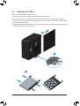
3-2 Installing a 3.5" Drive
Refer to the following steps to install a 3.5" drive:
1. Remove the two screws from the side panel. Then pull out the side panel.
2. Press the tabs of the 3.5" drive bracket on both sides to pull the bracket out of the desktop computer.
3. Secure your 3.5" drive into the bracket by inserting the four pins on the sides of the bracket into the mounting
holes on the sides of the drive.
4. Replace the bracket with the installed 3.5" drive in the desktop computer. Replace the side panel and secure
it with the screws you previously removed.
- 20 -
La page charge ...
La page charge ...
La page charge ...
La page charge ...
La page charge ...
La page charge ...
-
 1
1
-
 2
2
-
 3
3
-
 4
4
-
 5
5
-
 6
6
-
 7
7
-
 8
8
-
 9
9
-
 10
10
-
 11
11
-
 12
12
-
 13
13
-
 14
14
-
 15
15
-
 16
16
-
 17
17
-
 18
18
-
 19
19
-
 20
20
-
 21
21
-
 22
22
-
 23
23
-
 24
24
-
 25
25
-
 26
26


Gigabyte AORUS MODEL X 12th Le manuel du propriétaire
- Taper
- Le manuel du propriétaire
dans d''autres langues
Documents connexes
Autres documents
-
Asus PRIME X299-DELUXE II Manuel utilisateur
-
MSI MEG Z590 GODLIKE Le manuel du propriétaire
-
MSI MEG Z590 ACE Le manuel du propriétaire
-
Asus ProArt B760-CREATOR WIFI Manuel utilisateur
-
-
-
MSI MPG Z590 GAMING FORCE Le manuel du propriétaire
-
MSI MAG B560M MORTAR WIFI Le manuel du propriétaire
-
MSI MEG Z490 GODLIKE Le manuel du propriétaire