Lumination LRX Series LED Luminaire EMBB Retrofit Guide d'installation
- Taper
- Guide d'installation

LED.com
© 2023 Current Lighting Solutions, LLC. All rights reserved. Information and specifications subject to change
without notice. All values are design or typical values when measured under laboratory conditions.
Page 1 of 6
(Rev 05/19/23)
IND343 - Lumination LRX Series - LED Luminaire - EMBB Retrofit - Installation Guide_R01
Installation Guide
IND343
Lumination® LED Luminaire
EMBB Retrot
(LRX Series - LRXEMBBKIT07HE/LRXEMBBKIT07/LRXEMBBKIT10)
BEFORE YOU BEGIN / AVANT DE COMMENCER
Read these instructions and IOTA ILB-CP instruction manual completely and carefully.
Wear work gloves to prevent dirt and oil from being transferred to the luminaire.
IMPORTANT SAFEGUARDS / MESURES DE SÉCURITÉ IMPORTANTES
• Turn power o before inspection, installation or removal.
• Install this kit only in the luminaires that has the construction
features and dimensions shown in the photographs and /or
drawings.
• Installation of this retrot assembly requires a person familiar
with the construction and operation of the luminaire’s electrical
system and the hazard involved. If not qualied, do not attempt
installation. Contact a qualied electrician.
• To prevent wiring damage or abrasion, do not expose wiring to
edges of sheet metal or other sharp objects.
• Do not make or alter any open holes in an enclosure of wiring or
electrical components during kit installation.
• To prevent electrical shock, do not mate unit connector until
installation is complete and A.C. power is supplied to the unit.
• This kit provides more than one power supply output source. To
reduce the risk of electrical shock, disconnect both normal and
emergency sources by turning o the A.C. branch circuit and by
disconnecting the unit connector.
• Battery is a sealed unit. Components are not replaceable. Replace
the entire unit when necessary.
• Installation and servicing should be performed by qualied
personnel only. De-energize before opening.
• The kit is for use with grounded LED luminaires listed to UL
standards. Not for use in heated air outlets or hazardous
locations.
• The kit requires an unswitched A.C. power source of 120 to 277
volts, 50/60Hz.
• Do not mount near gas or electric heaters.
• The use of accessory equipment not recommended by
manufacturer may cause unsafe condition.
• The kit should be mounted in locations and at heights where
it will not readily be subjected to tampering by unauthorized
personnel.
• The kit and frame will supply output listed as bellowing for 90
minutes.
• For use in 0°C minimum, 40°C maximum ambient temperatures.
• Do not use this equipment for other than intended use.
• Install in accordance with the National Electrical Code and local
regulations.
• Lighting xture manufactures, electricians, and endusers need to
ensure product system compatibilit before nal installation.
• Couper l’alimentation avant l’inspection, l’installation ou d’eectuer de la
maintenance.
• Installer cette trousse seulement avec des luminaires possédant les caractéristiques
et dimensions montrées dans les photographies et / ou dessins.
• L’installation de cet assemblage rétro-t requière une personne familière avec la
construction et les modes d’opérations du système électrique du luminaire ainsi
que la connaissance des dangers inhérents à ce type d’installation. Ne pas installer
si non qualié, contacter plutôt un électricien qualié.
• Pour prévenir les dégâts ou l’abrasion du câblage électrique, éloigné ceux-ci des
rebords de métal et autre objets tranchants.
• Ne pas perforer ou altérer le boitier électrique ou tout autres composantes durant
l’installation de la trousse.
• Pour prévenir les chocs électriques, ne pas connecter le connecteur de l’unité de
la batterie avant que l’installation ne soit complétée et que le C.A. ne soit fourni à
l’unité.
• Cette trousse fournie plus d’une source de sortie d’alimentation. Pour réduire les
risques d’électrocution, déconnecter toutes les sources de courant en débranchant
le C.A. de la dérivation et aussi en déconnectant le connecteur de l’unité de la
batterie.
• La batterie est une unité scellée dont les composantes ne sont pas remplaçables.
Remplacer l’unité entière lorsque nécessaire.
• L’installation et la maintenance doivent être eectuée par du personnel qualié
seulement. Couper la tension avant de procéder.
• Cette trousse a été conçue pour être utilisé avec des luminaires DEL possédant une
mise à la terre et listé sous un standard UL. Ne pas utiliser pour un usage dans un
conduit d’air chaud ou dans des emplacements dangereux.
• Cette trousse requière une source d’alimentation en C.A. de 120 à 277 volts sans
interrupteur à 50/60Hz.
• L’utilisation d’équipement accessoire non recommandé par le manufacturier peut
causer des conditions dangereuses.
• Cette trousse devrait être installée dans un emplacement adéquat et à une hauteur
appropriée dans le but d’empêcher toute manipulation non autorisée.
• Il y a un risque de chute du luminaire s’il n’est pas installé correctement, suivre les
instructions d’installation avec attention.
• Cette trousse et ce châssis fourniront la source lumineuse répertoriée pour 90
minutes.
• Peut-être utilisé à une température ambiante entre 0°C minimum et 40°C maximum.
• Ne pas utiliser cet équipement pour autre chose que pour l’utilisation prévue.
• Installer en conformité avec le code électrique national et la réglementation locale.
• Les fabricants d’appareils d’éclairage, les électriciens et les utilisateurs naux
doivent s’assurer de la compatibilité du produit avant l’installation nale.

LED.com
© 2023 Current Lighting Solutions, LLC. All rights reserved. Information and specifications subject to change
without notice. All values are design or typical values when measured under laboratory conditions.
Page 2 of 6
(Rev 05/19/23)
IND343 - Lumination LRX Series - LED Luminaire - EMBB Retrofit - Installation Guide_R01
Lumination® (LRX - Series) Installation Guide
Kit vs Fixture
LRXR EMBB Fixture LRXR EMBB Frame Kit LRXS EMBB Fixture LRXS EMBB Frame Kit
SAP Description SAP Description SAP Description SAP Description
LRXR410ABBCCEL LRXEMBBKIT07HE LRXS410ABBCCEL LRXEMBBKIT07HE
LRXR610ABBCCEL FRAME6REL07 LRXS610ABBCCEL FRAME6SEL07
LRXR618ABBCCEL FRAME6REL10 LRXS618ABBCCEL FRAME6SEL10
LRXR618ABBCCEL FRAME6REL10 LRXS618ABBCCEL FRAME6SEL10
LRXR810ABBCCEL FRAME8REL07 LRXS810ABBCCEL FRAME8SEL07
LRXR818ABBCCEL FRAME8REL10 LRXS818ABBCCEL FRAME8SEL10
LRXR830ABBCCEL FRAME8REL10 LRXS830ABBCCEL FRAME8SEL10
LRXR840ABBCCEL LRXS840ABBCCEL
Nomenclature for LRX Series:
I - “A” Denotes color rendering index (CRI)
8 - 80
9 - 90
II - “BB” Denotes correlated color temperature (CCT)
27 - 2700K
30 - 3000K
35 - 3500K
40 - 4000K
50 - 5000K
Save These Instructions
Use only in the manner intended by the manufacturer. If you have any questions, contact the manufacturer.
LRXREL Fixture Thickness of Ceiling LRXSEL Fixture Thickness of Ceiling
SAP Description Max.(mm) SAP Description Max.(mm)
LRXR410ABBCCEL
15
LRXS410ABBCCEL
15LRXR610ABBCCEL LRXS610ABBCCEL
LRXR618ABBCCEL LRXS618ABBCCEL
LRXR618ABBCCEL
20
LRXS618ABBCCEL
20
LRXR810ABBCCEL LRXS810ABBCCEL
LRXR818ABBCCEL LRXS818ABBCCEL
LRXR830ABBCCEL LRXS830ABBCCEL
LRXR840ABBCCEL LRXS840ABBCCEL
III - “CC” Denotes dimming type
MD - 0-10V Dimming
PH - Phase cut Dimming
• LRXEMBBKIT07HE shall be mounted Max. 20.11 ft ( 6.12 m)
• LRXEMBBKIT07 shall be mounted Max. 22.71ft (6.92m)
• LRXEMBBKIT10 shall be mounted Max. 25.99ft (7.92m)
Thickness of ceiling is listed below:
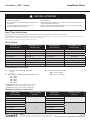
CAUTION / ATTENTION
• Fixture may fall down if not installed properly, follow
installation instructions.
• Wear safety glasses and proper aid during installation and
maintenance.
• Use only UL certied copper wire, wire connectors,
minimum 18AWG, minimum rated 75°C.
• Porter des lunettes de sécurité et utiliser des outils adéquats durant l’installation
et la maintenance.
• Utiliser seulement du câblage de cuivre classé 75°C et approuvé par UL pour les
connections d’entrées et de sorties.
• Utiliser des conducteurs de grosseur 18AWG minimum ou de grosseur 14AWG
dans le cas de montage en rangée continue.
NOTE: LRXEMBBKIT07HE, LRXEMBBKIT07 and LRXEMBBKIT10 are suitable for wet locations and are intended for covered ceiling installation only. The retrot kit is accepted as a component of a luminaire
where the suitability of the combination shall be determined by UL or authorities having jurisdiction.
Wear work gloves to prevent dirt and oil from being transferred to the luminaire.

LED.com
© 2023 Current Lighting Solutions, LLC. All rights reserved. Information and specifications subject to change
without notice. All values are design or typical values when measured under laboratory conditions.
Page 3 of 6
(Rev 05/19/23)
IND343 - Lumination LRX Series - LED Luminaire - EMBB Retrofit - Installation Guide_R01
Lumination® (LRX - Series) Installation Guide
Prepare Electrical Wiring
Electrical Requirements
• The luminaire must be supplied with 120-277 VAC,
50/60 Hz (In 120-277V application).
• Connected to an individual properly grounded branch
circuit, protected by a 15 or 20 ampere circuit breaker. Use
min. 75°C supply conductor.
Grounding Instructions
• The grounding and bonding of the overall system
shall be done in accordance with National Electric
Code (NEC) Article 600 and local codes.
Fixture Requirements
The units covered by this install instruction are intended to retrot
listed surface mounted luminaires, as well as type Non-IC recessed
mounted uorescent type luminaires. Please review Step 1 for an
example existing xture depiction.
Provided Item Qty.
1 LRX EMBB Frame Kit 1
2 LRX EMBB Fixture 1
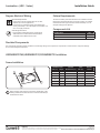
Components List
Provided Components
The components have been properly packed to avoid damage during transit. Inspect the components to conrm there is no physical damage.
Do not install damaged components.
LRXEMBBKIT07HE/LRXEMBBKIT07/LRXEMBBKIT10 Installation
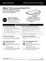
Frame Installation
1
Before retrot, verify that the junction box and bracket in the
existing installation are metal and are constructed similarly to
the illustration above.
Suitable Frame Bracket Hole Suitable
Fixture
Size (in.) Shape Dimensions (in.) Size (in.)
4 Round 12.60 x 7.64 x 3.54 4.20-5.50 LRXR4xxxxxxx
6Round 12.60 x 7.64 x 3.54 5.91-6.50 LRXR6xxxxxxx
8Round 15.55 x 11.34 x 3.54 7.68–8.27 LRXR8xxxxxxx
4Square 12.60 x 7.64 x 3.54 4.20-5.50 LRXS4xxxxxxx
6 Square 13.35 x 11.34 x 3.54 5.95-7.50 LRXS6xxxxxxx
8 Square 13.35 x 11.34 x 3.54 7.95-9.50 LRXS8xxxxxxx

LED.com
© 2023 Current Lighting Solutions, LLC. All rights reserved. Information and specifications subject to change
without notice. All values are design or typical values when measured under laboratory conditions.
Page 4 of 6
(Rev 05/19/23)
IND343 - Lumination LRX Series - LED Luminaire - EMBB Retrofit - Installation Guide_R01
Lumination® (LRX - Series) Installation Guide
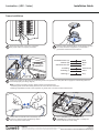
Frame Installation
2
Ensure that the power to the unit is turned o.
Use proper lockout and tagout procedures.
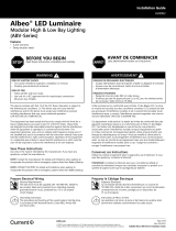
3
Remove existing downlight xture. Leave wiring in Junction
box. Verify that the AC supply line is provided with a
ground wire connected to the luminaire.
Connect AC and
dimming conduit
Junction
LRXEMBB IT07
LXREMBBKIT10
box
Dimming (optional)
AC line
Grounding
Dimming (+)
Unswitched Power (L1)
Common (N)
Switched Power (L2)
Dimming (–)
Black
White
Red
Yellow-Green
Violet
Gray
4
Connect the conduit for the xture AC and dimming leads to the junction box. Verify that the AC supply line and dimming leads are
connected properly (see wiring diagram).
Note: For phase cut dimming product, dimming leads can be disconnected
• If dimming leads will not be utilized, please do not remove the wire connectors.
• Dimming compatibility for both 0-10V and phase cut, please refer to Current’s website: www.LED.com
Connect AC and
dimming conduit
Junction
LRXEMBB IT07
LXREMBBKIT10
box
Dimming (optional)
AC line Grounding
Dimming (+)
Unswitched Power (L1)
Common (N)
Switched Power (L2)
Dimming (–)
Black
White
Red
Yellow-Green
Violet
Gray
“L” Bridge
Secure
battery
5
Connect male and female ends of the battery unit
connector. Then the battery will discharge. Please
refer to the picture shown above.
“L” Bridge
Secure
battery
6
Attach LRXEMBBKIT07HE, LRXEMBBKIT07 or
LRXEMBBKIT10 to existing frame with “L” bridge and
secure IOTA battery to the ceiling.

LED.com
© 2023 Current Lighting Solutions, LLC. All rights reserved. Information and specifications subject to change
without notice. All values are design or typical values when measured under laboratory conditions.
Page 5 of 6
(Rev 05/19/23)
IND343 - Lumination LRX Series - LED Luminaire - EMBB Retrofit - Installation Guide_R01
Lumination® (LRX - Series) Installation Guide
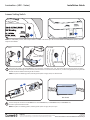
7
Attach the test switch to the LRX EMBB xture or junction box. If the xture is 6” or 8”, rst remove the nut from the end of test switch,
and put test switch through the hole of xture, then thread nut to test switch. If the xture is 4”, mount to the junction box and provided
exible conduit for remote mounting of the test switch.
Tighten nut on
Remove nut from
test switch
inside of housing
Attach to housing
4"
6" and 8” 6" and 8” 6" and 8”
Tighten nut on
Remove nut from
test switch
inside of housing
Attach to housing
4"
6" and 8” 6" and 8” 6" and 8”
Box closed
Box closed
8
Connect the quick connector of LRX EMBB xture and LRXEMBBKIT07( or LRXEMBBKIT07HE, or LRXEMBBKIT10)
and close quick connector box well.
NOTE: Forr 1000/650lm product, default output lumen is 1000lm. Push switch up or left to activate 650lm. For 4000/3000lm product, default
output level is 4000lm.
Lumens Setting Switch
Tighten nut on
Remove nut from
test switch
inside of housing
Attach to housing
4"
6" and 8” 6" and 8” 6" and 8”
Tighten nut on
Remove nut from
test switch
inside of housing
Attach to housing
4"
6" and 8” 6" and 8” 6" and 8”
NOTE: For phase cut dimming product, dimming leads (violet and gray wires) are disconnected.
NOTE: For phase cut dimming product, dimming leads (violet and gray wires) are open.

LED.com
© 2023 Current Lighting Solutions, LLC. All rights reserved. Information and specifications subject to change
without notice. All values are design or typical values when measured under laboratory conditions.
Page 6 of 6
(Rev 05/19/23)
IND343 - Lumination LRX Series - LED Luminaire - EMBB Retrofit - Installation Guide_R01
Lumination® (LRX - Series) Installation Guide
This device complies with Part 15 of the FCC Rules. Operation is subject to the following two conditions: (1) This device may not cause harmful interference, and
(2) this device must accept any interference received, including interference that may cause undesired operation. CAN ICES-005 (A)/NMB-005(A)
Note: This equipment has been tested and found to comply with the limits for a Class A digital device, pursuant to part 15 of the FCC Rules. These limits
are designed to provide reasonable protection against harmful interference when the equipment is operated in a commercial environment. This equipment
generates, uses, and can radiate radio frequency energy and, if not installed and used in accordance with the instruction manual, may cause harmful interference
to radio communications. Operation of this equipment in a residential area is likely to cause harmful interference in which case the user will be required to
correct the interference at his own expense.
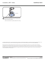
Load springs into upright position by twisting the springs
upward and carefully insert the xture to the hole of the
frame. Ensure xture is secure.
• All kit and frame will be completely addressed on ceiling.
9
Springs up
-
 1
1
-
 2
2
-
 3
3
-
 4
4
-
 5
5
-
 6
6


Lumination LRX Series LED Luminaire EMBB Retrofit Guide d'installation
- Taper
- Guide d'installation
dans d''autres langues
Documents connexes
-
Lumination LRX Series EMBB Guide d'installation
-
-
-
-
-
-
-
-
-
Autres documents
-
GE current LRXEMBBKIT10B Guide d'installation
-
Current IND668 Guide d'installation
-
GE current LRXB Series Guide d'installation
-
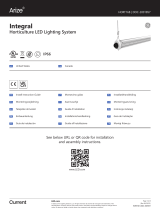 ARIZE Integral Guide d'installation
-
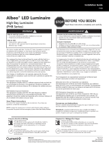 Albeo PHB Series Linear High Bay Guide d'installation
-
GE current IND674 Guide d'installation
-
Tetra Batten Gen 1 LED Signage Lighting Guide d'installation
-
 Albeo de Léclairage Modulaire des Baies Hautes et Basses de la Série ABC Guide d'installation
-
 Albeo AH2 Series Hazardous Locations Heavy Industrial High Bay Retrofit Kit Guide d'installation
-
 Albeo ABV Series Guide d'installation


