Skil AG290201 Le manuel du propriétaire
- Catégorie
- Outils électroportatifs
- Taper
- Le manuel du propriétaire

WARNING: To reduce the risk of injury, the user must read and understand the
Owner’s Manual before using this product. Save these instructions for future reference.
AVERTISSEMENT : Afin de réduire les risques de blessure, l’utilisateur doit lire et
comprendre le guide d’utilisation avant d’utiliser cet article. Conservez le présent guide
afin de pouvoir le consulter ultérieurement.
ADVERTENCIA : Para reducir el riesgo de lesiones, el usuario debe leer y comprender
el Manual del operador antes de utilizar este producto. Guarde estas instrucciones para
consultarlas en caso sea necesario.
Owner’s Manual
Guide d’utilisation
Manual del propietario
For Customer Service
Pour le service à la clientèle
Servicio al cliente
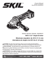
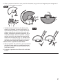
20V 4-1/2'' Angle Grinder
Meuleuse angulaire de 20 V (11,5 cm)
Amoladora de ángulo de 20 V de 4-1/2 pulg
1-877-SKIL-999 OR www.skil.com
Model/ Modelo/ Modèle: AG290201

2
TABLE OF CONTENTS
General Power Tool Safety Warnings . ............................3-4
Safety Warnings for Angle Grinder ...............................5-6
Symbols . . . . . . . . . . . . . . . . . . . . . . . . . . . . . . . . . . . . . . . . . . . . . . . . . . . . 7-10
Get to Know Your Angle Grinder ..................................11
Accessories ...................................................12
Specications .................................................12
Operating Instructions .......................................13-18
Maintenance ...................................................19
Troubleshooting ...............................................19
Limited Warranty of SKIL Consumer Tools ..........................20
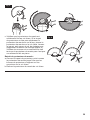
WARNING
• Some dust created by power sanding, sawing, grinding, drilling and other construction
activities contains chemicals known to the State of California to cause cancer, birth defects
or other reproductive harm. Some examples of these chemicals are:
– Lead from lead-based paints.
– Crystalline silica from bricks, cement, and other masonry products.
– Arsenic and chromium from chemically-treated lumber.
• Your risk from these exposures varies, depending upon how often you do this type of work.
To reduce your exposure to these chemicals:
– Work in a well-ventilated area.
– Work with approved safety equipment, such as dust masks that are specially designed to
lter out microscopic particles.
– Avoid prolonged contact with dust from power sanding, sawing, grinding, drilling, and
other construction activities. Wear protective clothing and wash exposed areas with soap
and water. Allowing dust to get into your mouth or eyes or to lie on the skin may promote
absorption of harmful chemicals.

3
GENERAL POWER TOOL SAFETY WARNINGS
WARNING Read all safety warnings and all instructions. Failure to follow the
warnings and instructions may result in electric shock, re and/or serious
injury.
SAVE ALL WARNINGS AND INSTRUCTIONS FOR FUTURE
REFERENCE.
The term "power tool" in the warnings refers to your mains-operated (corded) power tool or
battery-operated (cordless) power tool.
Work Area Safety
Keep work area clean and well lit. Cluttered or dark areas invite accidents.
Do not operate power tools in explosive atmospheres, such as in the presence of
ammable liquids, gases or dust. Power tools create sparks which may ignite the dust or
fumes.
Keep children and bystanders away while operating a power tool. Distractions can cause
you to lose control.
Electrical Safety
Power tool plugs must match the outlet. Never modify the plug in any way. Do not use
any adapter plugs with earthed (grounded) power tools. Unmodied plugs and matching
outlets will reduce risk of electric shock.
Avoid body contact with earthed or grounded surfaces, such as pipes, radiators,
ranges and refrigerators. There is an increased risk of electric shock if your body is earthed
or grounded.
Do not expose power tools to rain or wet conditions. Water entering a power tool will
increase the risk of electric shock.
Do not abuse the cord. Never use the cord for carrying, pulling or unplugging the power
tool. Keep cord away from heat, oil, sharp edges or moving parts. Damaged or entangled
cords increase the risk of electric shock.
When operating a power tool outdoors, use an extension cord suitable for outdoor use.
Use of a cord suitable for outdoor use reduces the risk of electric shock.
If operating a power tool in a damp location is unavoidable, use a ground fault circuit
interrupter (GFCI) protected supply. Use of an GFCI reduces the risk of electric shock.
Personal Safety
Stay alert, watch what you are doing and use common sense when operating a power
tool. Do not use a power tool while you are tired or under the influence of drugs,
alcohol or medication. A moment of inattention while operating power tools may result in
serious personal injury.
Use personal protective equipment. Always wear eye protection. Protective equipment
such as dust mask, non-skid safety shoes, hard hat, or hearing protection used for appropriate
conditions will reduce personal injuries.
Prevent unintentional starting. Ensure the switch is in the off-position before
connecting to power source and/or battery pack, picking up or carrying the tool.
Carrying power tools with your nger on the switch or energising power tools that have the
switch on invites accidents.

4
Remove any adjusting key or wrench before turning the power tool on. A wrench or a
key left attached to a rotating part of the power tool may result in personal injury.
Do not overreach. Keep proper footing and balance at all times. This enables better
control of the power tool in unexpected situations.
Dress properly. Do not wear loose clothing or jewellery. Keep your hair and clothing
away from moving parts. Loose clothes, jewellery or long hair can be caught in moving
parts.
If devices are provided for the connection of dust extraction and collection facilities,
ensure these are connected and properly used. Use of dust collection can reduce
dust-related hazards.
Power Tool Use And Care
Do not force the power tool. Use the correct power tool for your application. The correct
power tool will do the job better and safer at the rate for which it was designed.
Do not use the power tool if the switch does not turn it on and off. Any power tool that
cannot be controlled with the switch is dangerous and must be repaired.
Disconnect the plug from the power source and/or the battery pack from the power tool
before making any adjustments, changing accessories, or storing power tools. Such
preventive safety measures reduce the risk of starting the power tool accidentally.
Store idle power tools out of the reach of children and do not allow persons unfamiliar
with the power tool or these instructions to operate the power tool. Power tools are
dangerous in the hands of untrained users.
Maintain power tools. Check for misalignment or binding of moving parts, breakage of
parts and any other condition that may affect the power tool’s operation. If damaged,
have the power tool repaired before use. Many accidents are caused by poorly maintained
power tools.
Keep cutting tools sharp and clean. Properly maintained cutting tools with sharp cutting
edges are less likely to bind and are easier to control.
Use the power tool, accessories and tool bits etc. in accordance with these instructions,
taking into account the working conditions and the work to be performed. Use of the
power tool for operations different from those intended could result in a hazardous situation.
Battery Tool Use And Care
Recharge only with the charger specified by the manufacturer. A charger that is suitable
for one type of battery pack may create a risk of re when used with another battery pack.
Use power tools only with specifically designated battery packs. Use of any other battery
packs may create a risk of injury and re.
When battery pack is not in use, keep it away from other metal objects, like paper clips,
coins, keys, nails, screws or other small metal objects, that can make a connection
from one terminal to another. Shorting the battery terminals together may cause burns or a
re.
Under abusive conditions, liquid may be ejected from the battery; avoid contact. If
contact accidentally occurs, flush with water. If liquid contacts eyes, additionally seek
medical help. Liquid ejected from the battery may cause irritation or burns.
Service
Have your power tool serviced by a qualified repair person using only identical
replacement parts. This will ensure that the safety of the power tool is maintained.

5
SAFETY WARNINGS FOR ANGLE GRINDER
Safety Warnings Common For Grinding:
This power tool is intended to function as a grinder. Read all safety warnings,
instructions, illustrations and specifications provided with this power tool. Failure to
follow all instructions listed below may result in electric shock, re and/or serious injury.
Operations such as sanding, wire brushing, polishing or cutting-off are not
recommended to be performed with this power tool. Operations for which the power tool
was not designed may create a hazard and cause personal injury.
Do not use accessories which are not specifically designed and recommended by the
tool manufacturer. Just because the accessory can be attached to your power tool, it does
not assure safe operation.
The rated speed of the accessory must be at least equal to the maximum speed marked
on the power tool. Accessories running faster than their rated speed can break and y apart.
The outside diameter and the thickness of your accessory must be within the capacity
rating of your power tool. Incorrectly sized accessories cannot be adequately guarded or
controlled.
Threaded mounting of accessories must match the grinder spindle thread. For
accessories mounted by flange, the arbor hole of the accessory must fit the locating
diameter of the flange. Accessories that do not match the mounting hardware of the power
tool will run out of balance, vibrate excessively and may cause loss of control.
Do not use a damaged accessory. Before each use inspect the accessory such as
abrasive wheels for chips and cracks, backing pad for cracks, tear or excess wear,
wire brush for loose or cracked wires. If power tool or accessory is dropped, inspect
for damage or install an undamaged accessory. After inspecting and installing an
accessory, position yourself and bystanders away from the plane of the rotating
accessory and run the power tool at maximum no-load speed for one minute.
Damaged accessories will normally break apart during this test time.
Wear personal protective equipment. Depending on application, use face shield, safety
goggles or safety glasses. As appropriate, wear dust mask, hearing protectors, gloves
and workshop apron capable of stopping small abrasive or workpiece fragments. The
eye protection must be capable of stopping ying debris generated by various operations. The
dust mask or respirator must be capable of ltrating particles generated by your operation.
Prolonged exposure to high intensity noise may cause hearing loss.
Keep bystanders a safe distance away from work area. Anyone entering the work
area must wear personal protective equipment. Fragments of workpiece or of a broken
accessory may y away and cause injury beyond immediate area of operation.
Hold the power tool by insulated gripping surfaces only, when performing an operation
where the cutting tool may contact hidden wiring. Contact with a "live" wire will also make
exposed metal parts of the power tool "live" and could give the operator an electric shock.
Never lay the power tool down until the accessory has come to a complete stop. The
spinning accessory may grab the surface and pull the power tool out of your control.
Do not run the power tool while carrying it at your side. Accidental contact with the
spinning accessory could snag your clothing, pulling the accessory into your body.
Regularly clean the power tool’s air vents. The motor’s fan will draw the dust inside the
housing and excessive accumulation of powdered metal may cause electrical hazards.
Do not operate the power tool near flammable materials. Sparks could ignite these
materials.
Do not use accessories that require liquid coolants. Using water or other liquid coolants
may result in electrocution or shock.

6
Further Safety Instructions For All Operations
Kickback and Related Warnings:
Kickback is a sudden reaction to a pinched or snagged rotating wheel, backing pad, brush
or any other accessory. Pinching or snagging causes rapid stalling of the rotating accessory
which in turn causes the uncontrolled power tool to be forced in the direction opposite of the
accessory’s rotation at the point of the binding.
For example, if an abrasive wheel is snagged or pinched by the workpiece, the edge of the
wheel that is entering into the pinch point can dig into the surface of the material causing the
wheel to climb out or kick out. The wheel may either jump toward or away from the operator,
depending on direction of the wheel’s movement at the point of pinching. Abrasive wheels
may also break under these conditions.
Kickback is the result of power tool misuse and/or incorrect operating procedures or conditions
and can be avoided by taking proper precautions as given below.
Maintain a firm grip on the power tool and position your body and arm to allow you to
resist kickback forces. Always use auxiliary handle, if provided, for maximum control
over kickback or torque reaction during start-up. The operator can control torque reactions
or kickback forces, if proper precautions are taken.
Never place your hand near the rotating accessory. Accessory may kickback over your
hand.
Do not position your body in the area where power tool will move if kickback occurs.
Kickback will propel the tool in direction opposite to the wheel’s movement at the point of
snagging.
Use special care when working corners, sharp edges etc. Avoid bouncing and snagging
the accessory. Corners, sharp edges or bouncing have a tendency to snag the rotating
accessory and cause loss of control or kickback.
Do not attach a saw chain woodcarving blade or toothed saw blade. Such blades create
frequent kickback and loss of control.
Safety Warnings Specific for Grinding:
Use only wheel types that are recommended for your power tool and the specific guard
designed for the selected wheel. Wheels for which the power tool was not designed cannot
be adequately guarded and are unsafe.
The grinding surface of centre depressed wheels must be mounted below the plane of
the guard lip. An improperly mounted wheel that projects through the plane of the guard lip
cannot be adequately protected.
The guard must be securely attached to the power tool and positioned for maximum
safety, so the least amount of wheel is exposed towards the operator. The guard helps to
protect the operator from broken wheel fragments, accidental contact with wheel and sparks
that could ignite clothing.
Wheels must be used only for recommended applications. For example: do not grind
with the side of cut-off wheel. Abrasive cut-off wheels are intended for peripheral grinding,
side forces applied to these wheels may cause them to shatter.
Always use undamaged wheel flanges that are of correct size and shape for your
selected wheel. Proper wheel anges support the wheel thus reducing the possibility of wheel
breakage. Flanges for cut-off wheels may be different from grinding wheel anges.
Do not use worn down wheels from larger power tools. Wheel intended for larger power
tool is not suitable for the higher speed of a smaller tool and may burst.

7
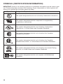
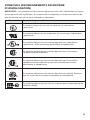
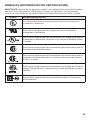
SYMBOLS
Safety Symbols
The purpose of safety symbols is to attract your attention to possible dangers. The safety sym-
bols and the explanations with them deserve your careful attention and understanding. The
symbol warnings do not, by themselves, eliminate any danger. The instructions andwarnings
they give are no substitutes for proper a cident prevention measures.
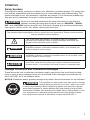
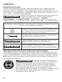
WARNING Be sure to read and understand all safety instructions in this Owner’s
Manual, including all safety alert symbols such as “DANGER,” “WARN-
ING,” and “CAUTION” before using this tool. Failure to following all instructions listed below
may result in electric shock, re, and/or serious personal injury.
The denitions below describe the level of severity for each signal word. Please read the manual
and pay attention to these symbols
This is the safety alert symbol. It is used to alert you to potential
personal injury hazards. Obey all safety messages that follow this
symbol to avoid possible injury or death.
DANGER DANGER indicates a hazardous situation which, if not avoided, will
result in death or serious injury.
WARNING WARNING indicates a hazardous situation which, if not avoided, could
result in death or serious injury.
CAUTION CAUTION, used with the safety alert symbol, indicates a hazardous
situation which, if not avoided, will result in minor or moderate injury.
Damage Prevention and Information Messages
These inform the user of important information and/or instructions that could lead to equip-
ment or other property damage if they are not followed. Each message is preceded by the
word “NOTICE”, as in the example below:
NOTICE: Equipment and/or property damage may result if these instructions are not followed.
WARNING The operation of any power tools can result in foreign
objects being thrown into your eyes, which can result
in severe eye damage. Before beginning power tool operation, always
wear safety goggles or safety glasses with side shields and a full face
shield when needed. We recommend a Wide Vision Safety Mask for use
over eyeglasses or standard safety glasses with side shields. Always
use eye protection which is marked to comply with ANSI Z87.1...

8
SYMBOLS (CONTINUED)
IMPORTANT: Some of the following symbols may be used on your tool. Please study them
and learn their meaning. Proper interpretation of these symbols will allow you to operate the
tool better and more safely.
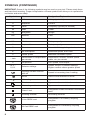
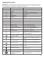
Symbol Name Designation/Explanation
V Volts Voltage (potential)
AAmperes Current
Hz Hertz Frequency (cycles per second)
WWatt Power
kg Kilograms Weight
min Minutes Time
s Seconds Time
Wh Watt-hours Battery capacity
Ah Ampere-Hours Battery capacity
ØDiameter Size of drill bits, grinding wheels, etc.
n0No load speed Rotational speed, at no load
nRated speed Maximum attainable speed
…/min Revolutions or reciprocation
per minute Revolutions, strokes, surface speed,
orbits, etc. per minute
0Off position Zero speed, zero torque...
1,2,3,…
I,II,III, Selector settings Speed, torque, or position settings.
Higher number means greater speed
Innitely variable selector
with off Speed is increasing from 0 setting
Arrow Action in the direction of arrow
Alternating current Type or a characteristic of current
Direct current Type or a characteristic of current
Alternating or direct current Type or a characteristic of current
Class II tool Designates Double Insulated Construction
tools.
Earthing terminal Grounding terminal
Li-ion RBRC seal Designates Li-ion battery recycling
program
Ni-Cad RBRC seal Designates Ni-Cad battery recycling
program

9
Symbol Name Designation/Explanation
Read manual symbol Alerts user to read manual
Wear eye protection symbol Alerts user to wear eye protection

10
SYMBOLS (CERTIFICATION INFORMATION)
IMPORTANT: Some of the following symbols for certication information may be used on your
tool. Please study them and learn their meaning. Proper interpretation of these symbols will
allow you to operate the tool better and more safely.
Symbol Designation/Explanation
This symbol designates that this tool is listed by Underwriters Laboratories.
This symbol designates that this component is recognized by
Underwriters Laboratories.
This symbol designates that this tool is listed by Underwriters
Laboratories, to United States and Canadian Standards.
This symbol designates that this tool is listed by the Canadian
Standards Association.
This symbol designates that this tool is listed by the Canadian
Standards Association, to United States and Canadian Standards.
This symbol designates that this tool is listed by the Intertek Testing
Services, to United States and Canadian Standards.
This symbol designates that this tool complies to NOM Mexican
Standards.

11
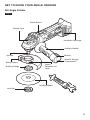
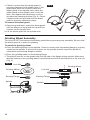
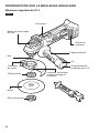
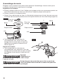
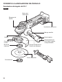
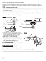
GET TO KNOW YOUR ANGLE GRINDER
20V Angle Grinder
Switch Button
Spindle Lock
Ventilation Openings
Auxiliary Handle
Wrench
Wrench Storage
Compartment
Wheel Guard Guard
Release/Lock
Latch
Backing Flange
Grinding Wheel
Lock Nut
Spindle
Fig. 1

12
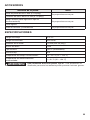
ACCESSORIES
Part Name Note
4-1/2” (Ø115 mm) Grinding Wheel Provided as a pair.
4-1/2” (Ø115 mm) Wheel Guard
Auxiliary Handle (Wrench on storage type) Provided as a pair.
Wrench
Backing Flange and Lock Nut Provided as a pair.
SPECIFICATIONS
Rated voltage 20V d.c.
Rated Speed 8500 /min
Wheel Diameter Ø4-1/2’’(115mm)
Wheel Thickness 6mm
Wheel Type Type 27 (only)
Spindle Thread M14
Recommended working temperature 14 ~ 104°F (-10 ~ 40°C)
Recommended storage temperature 32 ~ 104°F (0 ~ 40°C)
WARNING Use only Type 27 grinding wheels. Using accessories not designed for
this tool can cause serious injury.

13
OPERATING INSTRUCTIONS
WARNING To reduce the risk of fire, personal injury, and product damage due to
a short circuit, never immerse your tool, battery ack or charger in
fluid or allow a fluid to flow inside them. Corrosive or conductive uids, such as seawater,
certain industrial chemicals, and bleach or bleach-contain ng products, etc, can cause a short
circuit.
WARNING If any parts are damaged or missing, do not operate this product until
the parts are replaced. Use of this product with damaged or missing parts
could result in serious personal injury.
WARNING Do not attempt to modify this tool or create accessories not
recommended for use with this tool. Any such alteration or modication
is misuse and could result in a hazardous condition leading to possible serious injury.
WARNING To prevent accidental starting that could cause serious personal
injury, always remove the battery pack from the tool when assembling
parts.
This cordless angle grinder must be used only with the battery packs and charger listed below:
Battery Pack Charger
2Ah 2.5Ah 4Ah 5Ah SKIL SC535801
SKIL QC536001
SKIL BY519701
SKIL BY519702 SKIL BY519703 SKIL BY519601 SKIL BY519603
NOTICE: Please refer to the battery and charger manuals for detailed operating information.
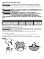
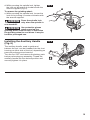
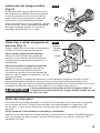
Wheel Guard Installation (Fig. 2, 3)
WARNING Use wheel guard with disc grinding wheels. Always close the latch to
secure the guard. Keep the guard between you and the wheel. Do not
direct the guard opening toward your body.
Turn the tool OFF and remove the battery pack before performing any assembly.
To install the wheel guard:
a. Open the guard latch and position the wheel guard on the spindle neck so that the two
bumps on the guard line up with the two notches on the spindle neck.
b. Rotate the wheel guard to the desired position, then close the latch to secure the guard in
place.
Fig. 2

14
c. Check to ensure that the wheel guard is
securely clamped to the spindle neck. If the
guard latch does not securely clamp the
wheel guard to the spindle neck, place the
wheel guard on the spindle neck, close the
latch, then tighten the adjustment screw to
increase the clamping tension (Fig. 3). Check
it again and do not proceed until the wheel
guard is properly clamped in place.
To remove the wheel guard:
a. Open the guard latch; rotate the wheel guard
until the bumps on the guard line up with the
notches on the spindle neck.
b. Lift the wheel guard off the spindle neck.
Grinding Wheel Assembly
Turn the tool OFF and remove the battery pack before performing any assembly. Be sure that
the wheel guard is in place for grinding.
To install the grinding wheel:
a. Place the backing ange on the spindle. Check to ensure that the backing ange is properly
seated on the spindle. It will click into place on the spindle and will cause the spindle to
rotate when the backing ange is rotated.
b. Place the grinding wheel on the backing ange.
c. Thread the lock nut on the spindle with the at side of the ange facing outside. Make sure
that the opening in the grinding wheel is positioned around the raised portion of the lock nut
(Fig. 4).
Fig. 4 Lock Nut
Lock Nut
Grinding Wheel
Grinding Wheel
Backing Flange Backing Flange
Spindle Spindle
Fig. 3

15
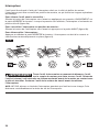
d. While pressing the spindle lock, tighten
the lock nut by turning it clockwise with the
wrench supplied (Fig. 5).
To remove the grinding wheel:
e. While pressing the spindle lock, loosen the
lock nut by turning it counter-clockwise with
the wrench supplied.
WARNING Press the spindle lock
only when the spindle is
at a standstill.
WARNING Use protective gloves
when removing the
grinding wheel from the tool, or first allow
the grinding wheel to cool down. It may be
hot after prolonged use.
Installing the Auxiliary Handle
(Fig. 6)
The auxiliary handle, used to guide and
balance the tool, can be threaded into the front
housing on either side of the tool, depending on
personal preference and comfort.
Turn the tool OFF and remove the battery pack
before performing any assembly. Thread the
auxiliary handle into the desired position and
securely tighten it in place.
Fig. 5
Fig. 6

16
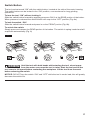
To Attach/Detach Battery Pack
(Fig. 7)
Be careful not to turn on the tool when
attaching the battery pack.
To attach the battery pack:
Align the raised rib on the battery pack with the
grooves in the tool, and then slide the battery
pack onto the tool.
To detach the battery pack:
Depress the battery-release button located
on the front of the battery pack to release the
battery pack. Pull the battery pack out and
remove it from the tool.
NOTICE: When placing the battery pack on the
tool, be sure that the raised rib on the battery pack aligns with the groove inside the tool and
that the latches snap into place properly. Improper attachment of the battery pack can cause
damage to internal components.
WARNING Battery tools are always in operating condition. Be careful when the
tool is not in use or when carrying it at your side.
Fig. 7
Battery-
Release
Button
Attach
Detach

17
Switch Button
The tool can be turned “ON” with the switch button, located at the side of the motor housing.
The switch button can be locked in the “ON” position, a convenience for long grinding
operations.
To turn the tool “ON” without locking it:
Slide the switch button forward by applying pressure ONLY at the REAR portion of the button.
When pressure is released the switch button will snap to the “OFF” position (Fig. 8a).
To lock the switch “ON”:
Slide the switch button forward and press in on the FRONT portion (Fig. 8b).
To unlock the switch:
Simply press and release the REAR portion of the button. The switch is spring loaded and will
snap back automatically (Fig. 8)
Fig. 8
WARNING Hold the tool with both hands while starting the tool, since torque
from the motor can cause the tool to twist. Start the tool and let the
tool come to full speed before contacting the workpiece. Lift the tool from the work
before releasing the switch.
NOTICE: DO NOT turn the switch “ON” and “OFF” while the tool is under load; this will greatly
decrease the switch life.

18
Grinding Operations
Selecting Grinding Wheels
WARNING Before using a grinding wheel, be certain that its maximum safe
operating speed is not exceeded by the nameplate speed of the
grinder. Do not exceed the recommended wheel diameter.
Disc Grinding Wheels
Grinding wheels should be carefully selected in order to use the grinder most efciently.
Wheels vary in type of abrasive, bond, hardness, grit size and structure. The correct type of
wheel to use is determined by the job. Use disc grinding wheels for fast grinding of structural
steel, heavy weld beads, steel casting, stainless steel, and other ferrous metals.
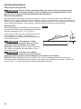
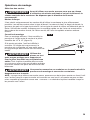
Grinding Tips
Efcient grinding is achieved by controlling the
pressure and keeping the angle between wheel
and the workpiece at 10° to 15° (Fig. 9).
If the wheel is at, the tool is difcult to control.
If the angle is too steep, the pressure is
concentrated on a small area causing burning
to the work surface.
WARNING Use clamps or other
practical way to secure
and support the workpiece to a stable
platform. Holding the work by hand or against
your body is unstable and may lead to loss of
control and injury.
WARNING Excessive or sudden
pressure on the wheel will
slow the grinding action and put dangerous stresses on the wheel.
NOTICE: When grinding with a new wheel, be certain to always grind while pulling tool
backwards until wheel becomes rounded on its edge. New wheels have sharp corners that
tend to “bite” or cut into work piece when pushing them forward.
15O
Fig. 9

19
MAINTENANCE
WARNING To avoid serious personal injury, always remove the battery pack
from the tool when cleaning or performing any maintenance.
Service
WARNING Preventive maintenance performed by unauthorized personnel may
result in misplacing of internal wires and components which could
cause serious hazard. We recommend that all tool service be performed by a SKIL Factory
Service Center or Authorized SKIL Service Station.
General Maintenance
WARNING When servicing, use only identical replacement parts. Use of any
other parts could create a hazard or cause product damage.
Periodically inspect the entire product for damaged, missing, or loose parts such as screws,
nuts, bolts, caps, etc. Tighten securely all fasteners and caps and do not operate this product
until all missing or damaged parts are replaced. Please contact customer service or an autho-
rized service center for assistance.
Cleaning
WARNING The tool may be cleaned most effectively with compressed dry air. Always
wear safety goggles when cleaning tools with compressed air.
Ventilation openings and switch levers must be kept clean and free of foreign matter. Do not
attempt to clean by inserting pointed objects through openings.
WARNING Certain cleaning agents and solvents damage plastic parts. Some of
these are: gasoline, carbon tetrachloride, chlorinated cleaning solvents,
ammonia and house hold detergents that contain ammonia.
Storage
Store the tool indoors in a place that is inaccessible to children. Keep away from corrosive
agents.
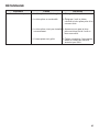
TROUBLE SHOOTING
Problem Cause Remedy
Tool will not start. 1. Battery pack is depleted.
2. Battery pack is over-
temperature.
3. Battery pack is not installed
properly.
4. Burned out switch.
1. Charge the battery.
2. Turn off the tool and cool the
battery pack under air ow.
3. Conrm battery is locked and
secured to the tool.
4. Have the switch replaced by
an Authorized SKIL Service
Center or Service Station.

20
LIMITED WARRANTY OF SKIL CONSUMER TOOLS
5 YEAR LIMITED WARRANTY
Chervon North America, Inc. ("Seller") warrants to the original purchaser only, that all SKIL
consumer TOOLS will be free from defects in material or workmanship for a period of ve
years from date of purchase, if original purchaser registers the product within 30 days from
purchase. BATTERIES AND CHARGERS are warranted for 2 years. Product registration
can be completed online at www.Registermyskil.com. Original purchasers should also retain
their receipt as proof of purchase. THE FIVE-YEAR WARRANTY PERIOD FOR TOOLS IS
CONDITIONED ON REGISTRATION OF THE PRODUCT WITHIN 30 DAYS OF PURCHASE.
If original purchasers do not register their product timely, the foregoing limited warranty will
apply for a duration of three years for tools. All batteries and chargers will remain under the
two-year limited warranty.
Notwithstanding the foregoing, if a SKIL consumer tool is used for industrial, professional
or commercial purposes, the foregoing warranty will apply for a duration of ninety days,
regardless of registration.
SELLER’S SOLE OBLIGATION AND YOUR EXCLUSIVE REMEDY under this Limited
Warranty and, to the extent permitted by law, any warranty or condition implied by law, shall
be the repair or replacement of parts, without charge, which are defective in material or
workmanship and which have not been misused, carelessly handled, or repaired by persons
other than Seller or Authorized Service Station. To make a claim under this Limited Warranty,
you must return the complete product, transportation prepaid, to any SKIL Factory Service
Center or Authorized Service Station. For Authorized SKIL Power Tool Service Stations,
please visit www.Registermyskil.com or call 1-877-SKIL-999 (1-877-754-5999).
THIS LIMITED WARRANTY DOES NOT APPLY TO ACCESSORY ITEMS SUCH AS
CIRCULAR SAW BLADES, DRILL BITS, ROUTER BITS, JIGSAW BLADES, SANDING
BELTS, GRINDING WHEELS AND OTHER RELATED ITEMS.
ANY IMPLIED WARRANTIES APPLICABLE TO A PRODUCT SHALL BE LIMITED IN
DURATION EQUAL TO THE DURATION OF THE EXPRESS WARRANTIES APPLICABLE
TO SUCH PRODUCT, AS SET FORTH IN THE FIRST PARAGRAPH ABOVE. SOME
STATES IN THE U.S., SOME CANADIAN PROVINCES DO NOT ALLOW LIMITATIONS ON
HOW LONG AN IMPLIED WARRANTY LASTS, SO THE ABOVE LIMITATION MAY NOT
APPLY TO YOU.
IN NO EVENT SHALL SELLER BE LIABLE FOR ANY INCIDENTAL OR CONSEQUENTIAL
DAMAGES (INCLUDING BUT NOT LIMITED TO LIABILITY FOR LOSS OF PROFITS)
ARISING FROM THE SALE OR USE OF THIS PRODUCT. SOME STATES IN THE U.S.
AND SOME CANADIAN PROVINCES DO NOT ALLOW THE EXCLUSION OR LIMITATION
OF INCIDENTAL OR CONSEQUENTIAL DAMAGES, SO THE ABOVE LIMITATION OR
EXCLUSION MAY NOT APPLY TO YOU.
THIS LIMITED WARRANTY GIVES YOU SPECIFIC LEGAL RIGHTS, AND YOU MAY ALSO
HAVE OTHER RIGHTS WHICH VARY FROM STATE TO STATE IN THE U.S., PROVINCE
TO PROVINCE IN CANADA AND FROM COUNTRY TO COUNTRY.
THIS LIMITED WARRANTY APPLIES ONLY TO PRODUCTS SOLD WITHIN THE UNITED
STATES OF AMERICA, CANADA AND THE COMMONWEALTH OF PUERTO RICO. FOR
WARRANTY COVERAGE WITHIN OTHER COUNTRIES, CONTACT YOUR LOCAL SKIL
DEALER OR IMPORTER.
© Chervon North America, 1203 E. Warrenville Rd, Naperville, IL 60563.
La page est en cours de chargement...
La page est en cours de chargement...
La page est en cours de chargement...
La page est en cours de chargement...
La page est en cours de chargement...
La page est en cours de chargement...
La page est en cours de chargement...
La page est en cours de chargement...
La page est en cours de chargement...
La page est en cours de chargement...
La page est en cours de chargement...
La page est en cours de chargement...
La page est en cours de chargement...
La page est en cours de chargement...
La page est en cours de chargement...
La page est en cours de chargement...
La page est en cours de chargement...
La page est en cours de chargement...
La page est en cours de chargement...
La page est en cours de chargement...
La page est en cours de chargement...
La page est en cours de chargement...
La page est en cours de chargement...
La page est en cours de chargement...
La page est en cours de chargement...
La page est en cours de chargement...
La page est en cours de chargement...
La page est en cours de chargement...
La page est en cours de chargement...
La page est en cours de chargement...
La page est en cours de chargement...
La page est en cours de chargement...
La page est en cours de chargement...
La page est en cours de chargement...
La page est en cours de chargement...
La page est en cours de chargement...
La page est en cours de chargement...
La page est en cours de chargement...
La page est en cours de chargement...
La page est en cours de chargement...
La page est en cours de chargement...
La page est en cours de chargement...
La page est en cours de chargement...
La page est en cours de chargement...
La page est en cours de chargement...
La page est en cours de chargement...
La page est en cours de chargement...
La page est en cours de chargement...
-
 1
1
-
 2
2
-
 3
3
-
 4
4
-
 5
5
-
 6
6
-
 7
7
-
 8
8
-
 9
9
-
 10
10
-
 11
11
-
 12
12
-
 13
13
-
 14
14
-
 15
15
-
 16
16
-
 17
17
-
 18
18
-
 19
19
-
 20
20
-
 21
21
-
 22
22
-
 23
23
-
 24
24
-
 25
25
-
 26
26
-
 27
27
-
 28
28
-
 29
29
-
 30
30
-
 31
31
-
 32
32
-
 33
33
-
 34
34
-
 35
35
-
 36
36
-
 37
37
-
 38
38
-
 39
39
-
 40
40
-
 41
41
-
 42
42
-
 43
43
-
 44
44
-
 45
45
-
 46
46
-
 47
47
-
 48
48
-
 49
49
-
 50
50
-
 51
51
-
 52
52
-
 53
53
-
 54
54
-
 55
55
-
 56
56
-
 57
57
-
 58
58
-
 59
59
-
 60
60
-
 61
61
-
 62
62
-
 63
63
-
 64
64
-
 65
65
-
 66
66
-
 67
67
-
 68
68


Skil AG290201 Le manuel du propriétaire
- Catégorie
- Outils électroportatifs
- Taper
- Le manuel du propriétaire
dans d''autres langues
- English: Skil AG290201 Owner's manual
- español: Skil AG290201 El manual del propietario
