Valor 2100HSC Le manuel du propriétaire
- Catégorie
- Cheminées
- Taper
- Le manuel du propriétaire
Ce manuel convient également à

©2019, Miles Industries Ltd.
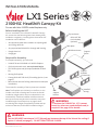
WARNING
This kit REQUIRES a minimum 2-1/2” [64 mm] gap between the top of the kit and the ceiling if
Option 1 is used (see page 2) . DO NOT SEAL THIS GAP CLOSED.
WARNING
To enclose the 2100HSC kit, 1/2” cement
board (or other non-combustible board) is
required. See page 10 for details.
4007800-02
2100HSC HeatShift Canopy Kit
For use with Valor 2100PK model fi replaces only
INSTALLATION MANUAL
LX1 Series
Before Installing the HSC
Prior to installation of the 2100HSC HeatShift Canopy
Kit, ensure that the following items have already been
installed or roughed in. Installing these items after HSC
installation can be diffi cult:
• All required drywall and insulation on adjoining wall
and ceiling above kit
• Any required wall thimble for through-wall venting
• Rough electrical
• Rough gas
Required for Assembly
To complete assembly, you will need:
• 2100HSC kit and 2100PKN or 2100PKP fi replace
• (2) kiln dried wood studs, cut to planned height
• (2) 5” Ø fl ex pipes and (4) clamps (available as LDK6
kit)
• Venting for fi replace
• Canopy Grille HSC-GR 14x6” (if installing Option 2, see
page 2).
• Wood screws and self-drilling sheet metal screws (see
Installation)
The screws for assembly of the kit pieces are included.
Note: The fi replace can sit directly on the fl oor, or the
installer can build a framing base to raise the overall
installation height (which may be combustible or non
combustible). Clearance between middle enclosure
and top enclosure may also be increased to vary total
installed height. See dimensions on page 2 when
considering base height (if applicable), middle and top
enclosure clearance, and overall installation height.
Top enclosure
Back plate
Middle enclosure
HeatShift
canopy
Support
frame
Support
brackets
(2, identical)
Wall
support
bracket
Grille HSC-GR
(not included,
optional)

2
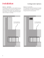
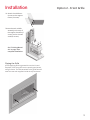
Configuration Options
Installation
Option 1 - Top Outlet Option 2 - Front Grille
This confi guration allows for a clean appearance up to a
required clearance of 2-1/2” from the ceiling. The heated
air from the fi replace escapes from this opening. It is
very important that this gap is never sealed with drywall,
crown molding, etc. If venting vertically, the vent pipe is
visible at the top of the assembly.
This confi guration allows a fi nish right up to the ceiling
by using a single front-facing grille to feed the heated
air back into the room. Note: Use only HeatShift
Canopy Grille HSC-GR, sold separately.
This space gets hot
and is NOT A SHELF.
This space gets hot
and is NOT A SHELF.

WARNING
This kit REQUIRES a minimum 2-1/2” [64
mm] gap between the top of the kit and
the ceiling if Option 1 is used (see page
2) . DO NOT SEAL THIS GAP CLOSED.
3
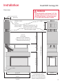
10-7/16”
[265 mm]
36” [915 mm]
(to bottom of feet)
14”
[356 mm]
21-7/16”
[545 mm]
71-7/16” [1815 mm]
(to bottom of feet)
13”
[330 mm]
42-13/16”
[1087 mm]
46-3/4”
[1188 mm]
(to wall)
18-1/2”
[470 mm]
OPTION 1 ONLY:
2-1/2”
[64 mm]
Minimum clear-
ance to ceiling
Separation allowable here - the
top enclosure may be installed
higher up the wall to increase
overall installation height
84-7/16”
[2145 mm]
Minimum TOTAL installation
height (from feet), with top and
middle enclosures touching
Base/pedestal NOT required
or included with this kit.
Installer can install a combus-
tible or non-combustible base
below the fi replace if desired.
Stud
HeatShift Canopy Kit
Installation
Dimensions

WARNING
Pre-insulate and drywall adjacent wall
as necessary (or required by local code).
This will aid drywall finishing and provide
separation between the HeatShift cavity
and the adjacent wall cavity.
4
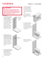
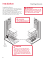
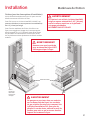
Installation
1. Place left hand stud (not
included, cut to planned
installation height)
vertically and fl at against
wall. Level and attach
to stud behind wall (or
provide secure backing
within wall for attach-
ment). Screw every
foot to planned height.
Suggested #10 x 3-1/2”
general purpose wood
screws, not included.
2. Fix right stud (not in-
cluded) to stud or solid
backing behind wall. Dis-
tance is 18-7/16” to the
outside of both studs.
You may use the middle
enclosure to check this
distance by temporar-
ily fi tting the enclosure
around the studs.Screw
every foot to planned
height.
3. If not done already, stop
and fi nish electrical and
gas installation while
you have room (see
“Electrical Wiring” and
“Gas Supply” in the LX1
Installer’s Manual).
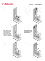
Option 1 - Top Outlet
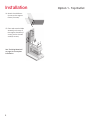
Installation
4. A bottom base or ped-
estal is not required
to install this kit. How-
ever, if one is preferred,
install it now and then
continue with remaining
steps.
5. Attached the wall sup-
port bracket to the
fi replace (4 self-drilling
screws).
6. Place fi replace against
the wall (with standoff s
and support bracket
between studs). Remove
carrying handles before
moving the fi replace into
fi nal position.
7. Square the fi replace to
the wall and screw feet
(4) to the fl oor.
Min. 2-1/2”
clearance
to fi nished
ceiling
18-7/16”
90°

5
Installation
8. Place the HeatShift
canopy on top of the
fi replace and screw
down (14 screws).
9. Complete any venting
installation still re-
quired prior to installing
remaining HeatShift
canopy kit.
Note: Two 45° elbows
(not included) attached
to the top of the fi re-
place as shown will be
required to off set the
vent for vertical venting.
10. Place and attach both
support brackets (identi-
cal) on top of the Heat-
Shift plenum as shown
(3 screws each).
11. Place the back plate at
planned installation
height (8 screws). This
plate provides separa-
tion from any adjacent
cavity. The top of the
plate must be a mini-
mum of 2-1/2” from the
fi nished ceiling.
12. Place the top enclosure
on top of the back plate
at the planned install
height (8 screws). The
top of the enclosure
must be fl ush with the
top of the back plate, a
minimum of 2-1/2” from
the fi nished ceiling.
13. Place the fl ex liners.
Clamp them at the top
and bottom of each liner
to the collars (4 clamps).
Min. 2-1/2”
clearance
to fi nished
ceiling
Option 1 - Top Outlet

6
Installation
14. Attach the middle en-
closure to the support
frame (3 screws).
15. Place and attach middle
assembly to the top of
the support brackets (6
screw), and to the wall
studs (8 screws).
See “Finishing Materials”
on page 10 to complete
installation.
Option 1 - Top Outlet

WARNING
Pre-insulate and drywall adjacent wall
as necessary (or required by local code).
This will aid drywall finishing and provide
separation between the HeatShift cavity
and the adjacent wall cavity.
7
Installation
1. Place left hand stud
(not included, cut to full
ceiling height) vertically
and fl at against wall.
Level and attach to stud
behind wall (or provide
secure backing within
wall for attachment).
Screw every foot to
planned height. Suggest-
ed #10 x 3-1/2” general
purpose wood screws,
not included.
2. Fix right stud (not in-
cluded) to stud or solid
backing behind wall. Dis-
tance is 18-7/16” to the
outside of both studs.
You may use the middle
enclosure to check this
distance by temporar-
ily fi tting the enclosure
around the studs.Screw
every foot to planned
height.
3. If not done already, stop
and fi nish electrical and
gas installation while
you have room (see
“Electrical Wiring” and
“Gas Supply” in the LX1
Installer’s Manual).
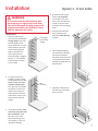
Option 2 - Front Grille
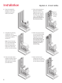
Installation
4. A bottom base or ped-
estal is not required
to install this kit. How-
ever, if one is preferred,
install it now and then
continue with remaining
steps.
5. Attached the wall sup-
port bracket to the
fi replace (4 self-drilling
screws).
6. Place fi replace against
the wall (with standoff s
and support bracket
between studs). Remove
carrying handles before
moving the fi replace into
fi nal position.
7. Square the fi replace to
the wall and screw feet
(4) to the fl oor.
Full height
to fi nished
ceiling
18-7/16”
90°

8
Installation
8. Place the HeatShift
canopy on top of the
fi replace and screw
down (14 screws).
9. Complete any venting
installation still re-
quired prior to installing
remaining HeatShift
canopy kit.
Note: Two 45° elbows
(not included) attached
to the top of the fi re-
place as shown will be
required to off set the
vent for vertical venting.
10. Place and attach both
support brackets (identi-
cal) on top of the Heat-
Shift plenum as shown
(3 screws each).
11. Place the back plate at
planned installation
height (8 screws). This
plate provides separa-
tion from any adjacent
cavity. The top of the
plate must be fl ush to
the fi nished ceiling.
12. Place the top enclosure
on top of the back plate
at the planned install
height (8 screws). The
top of the enclosure
must be fl ush with the
top of the back plate,
and fl ush to the fi n-
ished ceiling.
13. Place the fl ex liners.
Clamp them at the top
and bottom of each liner
to the collars (4 clamps).
Mount
fl ush to
fi nished
ceiling
Option 2 - Front Grille

9
Installation
14. Attach the middle en-
closure to the support
frame (3 screws).
Place and attach middle
assembly to the top of
the support brackets (6
screw), and to the wall
studs (8 screws).
See “Finishing Materi-
als” on page 10 to
complete installation.
Option 2 - Front Grille
Placing the Grille
AFTER applying fi nishing materials over the kit and
fi replace, insert the grille into the opening and attach
using 2 screws. The tabs attached to the grille face will
meet the two tabs supplied inside the top enclosure.

WARNING
This kit REQUIRES a minimum 2-1/2” [64
mm] gap between the top of the kit and
the ceiling if Option 1 is used (see page
2) . DO NOT SEAL THIS GAP CLOSED.
10
Finishing Materials
Installation
Finishing (Both Options)
See the LX1 Installer’s Manual for fi nishing materials de-
tails. To enclose the 2100HSC kit, 1/2” cement board (or
other non-combustible board) is required.
When attaching fi nishing materials to steel frame or fi re-
place body, we suggest using self-drilling screws, 1-1/2”
length. Note: you may be penetrating two layers of sheet
metal depending on where you choose to fasten.
Min 3”
above
bottom of
opening
WARNING
Do not drill or drive screws into these
marked areas (on both sides)! Electrical
and gas services are located here. See
LX1 Installer’s Manual for more detail. If
in doubt, remove the bottom plates from
the opening and verify what is behind the
panels.
WARNING
Ensure weight of wall above is
NOT carried by the appliance.
Bottom panels

11
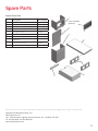
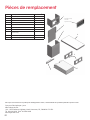
Spare Parts
1
2
3
7
4
6
5
8 (not included,
optional)
Description Part Number
1 Top enclosure with collars 4007698
2 Back cover plate 4007698
3Middle enclosure 4007691
4Support frame 4007689
5 Wall support bracket 4007820
6 Support bracket (2) 4007690
7HeatShift canopy 4007699
8 14x6” grille (OPTIONAL, not included in
2100HSC kit)
HSC-GR
#8 1/2” S/T screws (29) 4004560
#8 1/2” Philips self-drilling screws (4) 4007834
Repair Parts List
Designed and Manufactured by / for
Miles Industries Ltd.
190 – 2255 Dollarton Highway, North Vancouver, B.C., CANADA V7H 3B1
Tel. 604-984-3496 Fax 604-984-0246
www.valorfi replaces.com
Because our policy is one of constant development and improvement, details may vary slightly from those given in this publication.

12
©2019, Miles Industries Ltd.
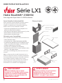
AVERTISSEMENT
Un panneau de béton (ou autre panneau
incombustible) de 1/2 po [13 mm]
d’épaisseur est exigé autour de la Hotte
HeatShift—voir page 21 pour détails.
AVERTISSEMENT
La Hotte HeatShift exige un espace
minimal de 2-1/2” [64 mm] entre le caisson
supérieur et le plafond lorsqu’installée
selon l’option 1—voir page suivante. NE
FERMEZ PAS CET ESPACE!
Hotte HeatShift
®
2100HSC
Pour usage avec foyers Valor LX1 2100P seulement
DIRECTIVES D’INSTALLATION
Série LX1
Avant d’installer la Hotte HeatShift
Avant d’installer la Hotte HeatShift 2100HSC, assurez-
vous que les accessoires suivants aient déjà été
installés. L’installation de ces accessoires peut être
diffi cile une fois la Hotte HeatShift installée :
• L’isolant et le placoplâtre sur le mur adjacent et le
plafond au-dessus de l’installation;
• Fourreau pour évacuation à travers le mur s’il y a lieu;
• Raccordement sommaire de l’électricité;
• Raccordement sommaire du gaz.
Nécessaire pour l’assemblage
Pour compléter cette installation, vous avez besoin de :
• Hotte HeatShift et foyer
• 2 poteaux de bois, coupé à la hauteur planifi ée
• 2 conduits fl ex d’aluminium 5 po de diamètre UL-181
Classe 1 et 4 colliers de serrage - ou Conduits LDK6
• Conduits d’évacuation pour le foyer
• Vis à bois et vis à métaux (voir installation)
• Grille de hotte HSC-GR 14” x 6” pour installation selon
l’option 2—voir page suivante
Les vis pour l’assemblage des pièces de la Hotte sont
incluses.
Note : Le foyer peut être installé directement sur le
plancher or peut être situé sur une base (combustible
ou incombustible) contruite pour atteindre la hauteur
de l’installation désirée. L’espace entre les deux
caissons peut varier selon la hauteur de l’installation.
Voir les dimensions à la page suivante pour plus
d’information sur la hauteur et les dégagements.
Pièces principales
Caisson supérieur avec buses
Plaque arrière
Caisson inférieur
Hotte avec
buses
Plaque-support
Supports (2)
Support
mural
Grille HSC-GR
(optionnelle,
vendue séparément)

13
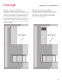
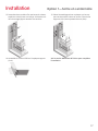
Options d’installation
Concept
Option 2 - Sortie avant avec grille
Cette option permet d’appliquer la fi nition du mur
jusqu’au plafond. L’air chaud produit par le foyer sera
explusé par une grille installée sur la paroi avant.
Note : N’utilisez que la Grille pour hotte HeatShift
HSC-GR, vendue séparément.
Option 1 - Sortie en cantonnière
Cette option à l’apparence plus épurée exige un
dégagement de 2-1/2” [64 mm] entre le haut du caisson
supérieur et le plafond. L’air chaud du foyer monte par
convection et est explusé par cette ouverture. Il est
donc très important que cet espace en haut du mur
ne soit jamais fermé ou obstrué par un matériau de
fi nition, moulure ou autre. Si l’évacuation du foyer est
faite par un conduit d’évacuation à travers le plafond, le
conduit sera visible.
Cette surface n’est
pas une tablette
Cette surface n’est
pas une tablette

14
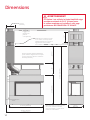
AVERTISSEMENT
Si l’Option 1 est utilisée, la Hotte HeatShift exige
un espace minimal de 2-1/2” [64 mm] entre
le caisson supérieur et le plafond—voir page
précédente. NE FERMEZ PAS CET ESPACE!
10-7/16”
[265 mm]
Poteaux
36” [915 mm]
(du bas de l’appareil)
14”
[356 mm]
21-7/16”
[545 mm]
71-7/16” [1815 mm]
(du bas de l’appareil)
13”
[330 mm]
42-13/16” [1087 mm]
46-3/4” [1188 mm]
(jusqu’au mur)
18-1/2”
[470 mm]
OPTION 1
Dégagement
minimum du
plafondb:
2-1/2” [64 mm]
Séparation des caissons permise
ici - le caisson du haut peut être
installé plus haut sur le mur pour
augmenter la hauteur totale
de l’installation
Hauteur minimale totale d’installation à
partir du bas de l’appareil et sans espace
entre les caissons supérieur et inférieur :
84-7/16” [2145 mm]
Base/piédestal non exigés ou inclus
avec ce kit. Si désirée, une base
peut être installée et construite de
matériaux combustibles.
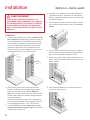
Dimensions

15
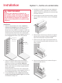
AVERTISSEMENT
Isolez le mur adjacent et finissez-le au
placoplâtre tel que nécessaire (ou exigé par
les normes locales). Ceci aidera à la finition
du placoplâtre et fournira une séparation
entre la cavité HeatShift et la cavité du mur
adjacent.
Installation
1. Placez l’un des poteaux (non inclus, coupés à la
hauteur de l’installation) verticalement, à plat sur
le mur où sera le côté gauche de l’installation (y
faisant face). Pour solidifi er l’installation, il sera utile
de le situer vis-à-vis un autre poteau derrière le mur.
Nivelez le poteau et fi xez-le au mur à chaque pied
sur la hauteur nécessaire. Nous suggérons des vis à
bois d’usage général #10 x 3-1/2”, non-incluses.
2. Placez l’autre poteau (non inclus) à la droite du
premier. La distance de l’extérieur d’un poteau à
l’extérieur de l’autre est de 18-7/16” [468 mm].
Note : Vous pouvez utiliser le caisson inférieur pour
vérifi er cette distance en le fi xant temporairement
autour des poteaux.
Nivelez le poteau et fi xez-le au mur à chaque pied
sur la hauteur nécessaire. Nous suggérons des vis à
bois d’usage général #10 x 3-1/2”, non-incluses.
3. Si cela n’a pas déjà été fait, arrêtez-vous ici et rac-
cordez le courant électrique et le gaz. Voir le Guide
d’installation du foyer LX1.
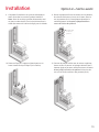
Option 1—Sortie en cantonnière
Installation
Dégagement
min. de 2-1/2”
[64 mm]du
plafond fi ni
18-7/16”
[468 mm]
90°
4. Une base ou un piédestal ne sont par exigés pour
l’installation de ce kit. Cependant, si une base est
désirée, installez-la maintenant puis continuez avec
les étapes suivantes.
5. Fixez le support mural à la caisse du foyer, côté du
mur, au-dessus des écarteurs, avec 4 vis auto-per-
çeuses.
6. Placez le foyer contre le mur, écarteurs et support
mural entre les poteaux. Enlevez les poignées du
foyer avant de le placer en position fi nale.
7. Assurez-vous que le foyer soit perpendiculaire au
mur et vissez ses quatre pattes au plancher ou à la
base si utilisée.
8. Placez la hotte HeatShift sur la caisse du foyer et
vissez-la en place (14 vis).

16
Dégagement
min. de 2-1/2”
[64 mm]du
plafond fi ni
Option 1—Sortie en cantonnière
Installation
9. Complétez l’installation du système d’évacuation
avant d’installer le reste du système HeatShift.
Note : Dans le cas d’un système d’évacuation verti-
cal, deux coudes de 45° (non inclus) doivent être in-
stallé directement à la buse du foyer pour le décaler.
10. Placez et fi xez les 2 supports (identiques) sur la
hotte HeatShift tel qu’indiqué (3 vis chacun).
11. Placez la plaque arrière à la hauteur de l’installation,
les rebords verticaux en haut, vers l’avant; fi xez-la
sur les poteaux (8 vis). Cette plaque sépare de la
cavité adjacente.
Le haut de la plaque doit être à au
moins 2-1/2” [64 mm] de la fi nition du plafond.
12. Couvrez la plaque arrière avec le caisson supérieur,
buses en bas.Le caisson et la plaque doivent être à
hauteur égale et forment une boîte ouverte située à
au moins 2-1/2” [64 mm] de la fi nition du plafond..
Vissez le caisson sur les côtés extérieurs des pote-
aux (8 vis).

17
Option 1—Sortie en cantonnière
Installation
13. Raccordez deux conduits fl ex aux buses du caisson
supérieur et de la hotte sur le foyer. Utilisez des col-
liers de serrage (4) pour attacher les conduits.
14. Assemblez le caisson inférieur à la plaque-support
(3 vis).
15. Placez l’assemblage caisson et plaque sur les sup-
ports au-dessus de la hotte et au mur. Fixez-le aux
supports (6 vis) et aux poteaux du mur (8 vis).
Voir la section Matériaux de fi nition pour compléter
l’installation.

18
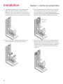
AVERTISSEMENT
Isolez le mur adjacent et finissez-le au
placoplâtre tel que nécessaire (ou exigé par
les normes locales). Ceci aidera à la finition
du placoplâtre et fournira une séparation
entre la cavité HeatShift et la cavité du mur
adjacent.
Installation
1. Placez l’un des poteaux (non inclus, coupés à la hau-
teur du plafond) verticalement, à plat sur le mur où
sera le côté gauche de l’installation (y faisant face).
Pour solidifi er l’installation, il sera utile de le situer
vis-à-vis un autre poteau derrière le mur. Nivelez
le poteau et fi xez-le au mur à chaque pied sur la
hauteur nécessaire. Nous suggérons des vis à bois
d’usage général #10 x 3-1/2”, non-incluses.
2. Placez l’autre poteau (non inclus) à la droite du
premier. La distance de l’extérieur d’un poteau à
l’extérieur de l’autre est de 18-7/16” [468 mm].
Note : Vous pouvez utiliser le caisson inférieur pour
vérifi er cette distance en le fi xant temporairement
autour des poteaux.
Nivelez le poteau et fi xez-le au mur à chaque pied
sur la hauteur nécessaire. Nous suggérons des vis à
bois d’usage général #10 x 3-1/2”, non-incluses.
3. Si cela n’a pas déjà été fait, arrêtez-vous ici et rac-
cordez le courant électrique et le gaz. Voir le Guide
d’installation du foyer LX1.
Option 2—Sortie avant
Installation
4. Une base ou un piédestal ne sont par exigés pour
l’installation de ce kit. Cependant, si une base est
désirée, installez-la maintenant puis continuez avec
les étapes suivantes.
5. Fixez le support mural à la caisse du foyer, côté du
mur, au-dessus des écarteurs, avec 4 vis auto-per-
çeuses.
6. Placez le foyer contre le mur, écarteurs et support
mural entre les poteaux. Enlevez les poignées du
foyer avant de le placer en position fi nale.
7. Assurez-vous que le foyer soit perpendiculaire au
mur et vissez ses quatre pattes au plancher ou à la
base si utilisée.
8. Placez la hotte HeatShift sur la caisse du foyer et
vissez-la en place (14 vis).
Pleine
hauteur
jusqu’à la
fi nition du
plafond
18-7/16”
[468 mm]
90°

19
Installez égal
au fi ni du
plafond
9. Complétez l’installation du système d’évacuation
avant d’installer le reste du système HeatShift.
Note : Dans le cas d’un système d’évacuation verti-
cal, deux coudes de 45° (non inclus) doivent être in-
stallé directement à la buse du foyer pour le décaler.
10. Placez et fi xez les 2 supports (identiques) sur la
hotte HeatShift tel qu’indiqué (3 vis chacun).
11. Placez la plaque arrière à la hauteur de l’installation,
les rebords verticaux en haut, vers l’avant; fi xez-la
sur les poteaux (8 vis). Cette plaque sépare de la
cavité adjacente.
Le haut de la plaque doit être
contre la fi nition du plafond.
12. Couvrez la plaque arrière avec le caisson supérieur,
buses en bas.Le caisson et la plaque doivent être à
hauteur égale et forment une boîte ouverte à l’avant
allant jusqu’à la fi nition du plafond. Vissez le cais-
son sur les côtés extérieurs des poteaux (8 vis).
Option 2—Sortie avant
Installation

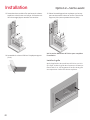
20
Installez la grille
Après l’application des matériaux de fi nition sur le kit
et le foyer, insérez la grille dans l’ouverture à l’avant et
fi xez-la avec 2 vis. Les languettes à l’arrière de la grille
correspondront à celles du caisson supérieur.
13. Raccordez deux conduits fl ex aux buses du caisson
supérieur et de la hotte sur le foyer. Utilisez des col-
liers de serrage (4) pour attacher les conduits.
14. Assemblez le caisson inférieur à la plaque-support
(3 vis).
15. Placez l’assemblage caisson et plaque sur les sup-
ports au-dessus de la hotte et au mur. Fixez-le aux
supports (6 vis) et aux poteaux du mur (8 vis).
Voir la section Matériaux de fi nition pour compléter
l’installation.
Option 2—Sortie avant
Installation
La page est en cours de chargement...
La page est en cours de chargement...
-
 1
1
-
 2
2
-
 3
3
-
 4
4
-
 5
5
-
 6
6
-
 7
7
-
 8
8
-
 9
9
-
 10
10
-
 11
11
-
 12
12
-
 13
13
-
 14
14
-
 15
15
-
 16
16
-
 17
17
-
 18
18
-
 19
19
-
 20
20
-
 21
21
-
 22
22


Valor 2100HSC Le manuel du propriétaire
- Catégorie
- Cheminées
- Taper
- Le manuel du propriétaire
- Ce manuel convient également à
dans d''autres langues
- English: Valor 2100HSC Owner's manual
Documents connexes
-
Valor 2100SFK Le manuel du propriétaire
-
-
-
-
-
-
-
-