
tip. Montagnani - Modena - Cod. 535017 1003 - MADE IN ITALY
x GB
INSTRUCTIONS BOOKLET
mod.
x FR
NOTICE D'EMPLOI
ET ENTRETIEN

3 3
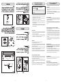
The first time the oven is used, it may give off acrid smells, caused
by the first heating of isolating panels glue surrounding the oven
(it is necessary to heat up the oven at the maximum
temperature for about 30-40 minutes with closed door).
It is something normal, and in case it will occur, wait for the smoke
to stop before introducing the food into the oven.
The oven is fitted with: a rod shelf for cooking food contained in
oven dishes or placed directly on the rod shelf itself, a drip-tray
for cooking sweets, biscuits, pizzas, etc., or for collecting juices
and fats from food cooked directly on the rod shelf.
warnings: do not cook foods on the bottom in the base of
the oven.
GAS OVEN
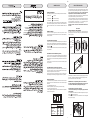
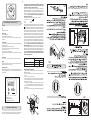
MANUAL IGNITION OF OVEN BURNER
To ignite the oven burner, simply insert a match through the
opening (fig. 2) and then turn the tap to the maximum setting as
shown in figure 1.
Electric ignition of oven burner (optional)
The oven door must always be completely open, before the
burner ignition.
Turn the knob anti-clockwise to the maximum position, then press
button to ignite the burner.
In case there is no electric current, the burner can also be lighted
using a match. (fig 2).
USE OF THE GAS OVEN
210
170
140
250
1
2
3
4
5
6
7
8
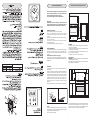
WORK-TOP USE
USING GAS BURNERS
The following symbols are on the control panel next to each knob:
- Black circle gas off
- Large flame maximum setting
- Small flame minimum setting
The minimum position is at the end of the anti-clockwise rotation
of the knob. All operation positions must be chosen between the
positions of max. and min., never choose them between max. and
off.
MANUAL IGNITION
To turn on a burner, approach a match to it, press the knob
corresponding to the selected burner and turn it anticlockwise to
the max position.
ELECTRIC IGNITION (optional)
To turn on a burner, press the knob corresponding to the selected
burner and turn it anticlockwise to the max position; simultaneously
pressing the electric ignition button on the control panel marked
with symbol .
In case there is no electric current, the burner can also be lighted
using a match.
AUTOMATIC ELECTRIC IGNITION (optional)
To turn on a burner, press the knob corresponding to the selected
burner and turn it anticlockwise to the max position. Keeping the
knob pressed, the electric automatic ignition of the burner will be
started up.
In case there is no electric current, the burner can also be lighted
using a match.
APPLIANCES WITH SAFETY VALVE (optional)
Follow the same procedure described above to ignite the burners.
In this case, however, once you have turned the knob to the open
setting, hold it pressed in for 10 seconds.
If for any reason the burner flame goes out, the safety valve
automatically shuts off the gas supply to the burner in question.
ENERGY SAVING TIPS
• The diameter of the pan bottom should be the same as that of
the burner. The burner flame must never come out from the pans
diameter.
• Use flat-bottomed pans only.
• Whenever possible, keep a lid on the pan while cooking.
You will not need as much heat.
• Cook vegetables, potatoes, etc. with as little water as possible
to reduce cooking times.
= CLOSED
= MINIMUM
= MAXIMUM
= GRILL
Pos.1 : 140°C
Pos.8 : 250°C
GB
After making sure that the burner has lit properly, gently close the
oven door. To obtain the temperature required, simply turn the
pointer of the knob to the chosen number .
WARNING: Do not operate the ignition for more than 15
seconds. If the burner fails to ignite, leave the oven door open
for at least 1 minute before pressing the knob again.
Fig. 3
Fig. 2
Fig. 1
BURNERS PANS
Ø min. Ø max
RAPIDE 180 mm 320 mm
SEMIRAPIDE 120 mm 220 mm
AUXILIARY 80 mm 180 mm
TRIPLE CROWN 220 mm 320 mm
ULTRARAPID 220 mm 320 mm
.93/68/EEC
.89/109/EEC
.90/396/EEC
.89/336/EEC
.73/23/EEC

4 4
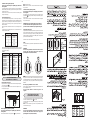
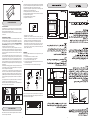
Manual ignition of the grill
Open the oven door, then turn the oven knob to the right and place
it on the grill position .
Bring a light match near the holes of the burner placed on the
oven upper part (fig.4).
1
2
3
4
5
6
7
8
210
170
140
250
Use of the gas grill with the oven door closed
Some models are designed for the grill to be used with the oven
door completely closed.
In this case the deflector S shown in fig. 5B is not
supplied.
USE OF THE ELECTRIC GRILL
(ACCORDING TO THE MODELS)
Electric ignition of grill burner (optional)
The oven door must always be completely open, before the
burner ignition.
Turn the knob clockwise to the grill position , then press button
In some other appliances the electric grill can be operated turning
the knob clockwise on position (fig C-D).
A warning light on the control panel will light up to inform you that
the grill is on.
Note: In some models the grill knob is separated from the
thermostat knob. (fig C)
Automatic electric ignition (optional)
The oven door must always be completely open, before the
burner ignition.
To ignite the burner, press the knob and turn it clockwise to the
grill position . Keep it pressed to start up the automatic ignition
of the burner.
In case there is no electric current, the burner can also be lighted
using a match (fig.4).
WARNING: Do not operate the ignition for more than 15
seconds. If the burner fails to ignite, leave the oven door
open for at least 1 minute before pressing the knob again.
Burner with safety device
Repeat the above mentioned procedure, and press the oven knob
at the same time. When the burner is on, keep the knob pressed
for about 10 seconds (fig.3). In this way the safety valve will be
started up. If for any reason the burner flame goes out, repeat the
procedure as described above..
Heat the oven 5 minutes before introducing the food.
NOTE :
In some models the grill knob is separated from the thermostat
knob.(fig A).
Automatic electric ignition (optional)
The oven door must always be completely open, before the
burner ignition
To ignite the burner, press the knob and turn it anti-clockwise to
the maximum position. Keep it pressed to start up the automatic
ignition of the burner.
In case there is no electric current, the burner can also be lighted
using a match.(fig 2).
Burner with safety device
For burners fitted with safety device, it it necessary to keep on
pressing the concerned knob for about 10 seconds after the ignition
(fig.3). In this way the safety valve will be started up. If for any
reason the burner flame goes out, repeat the procedure as
described above.
When you will be sure that the burner is on, close softly the oven
door.
To obtain the desired temperature, turn the knob index to the
selected number (tab.B).
TAB. C
TAB. B
USE OF THE GAS GRILL
(ACCORDING TO THE MODELS)
WARNINGS: To turn the oven light on, press switch .
Fig. A
Fig. 4
WARNING:
Do not use the grill burner and the oven burner at one and
the same time, other than for the exclusive purpose of
preheating the oven (max 10/20 minutes)
NOTE:
The grill must be used with the door half-open (see fig5 A).
Fit the deflector S onto the centring pins N on the top of the oven
opening (fig.5 B ). Then gently close the oven door against the
deflector.
to ignite the burner.
In case there is no electric current, the burner can also be lighted
using a match.
Knob position Temperature °C
1 140 °C
2 150 °C
3 160 °C
4 170 °C
5 190 °C
6 210 °C
7 230 °C
8 250 °C
WARNING:
Do not use the grill burner and the oven burner at one and
the same time, other than for the exclusive purpose of
preheating the oven (max 10/20 minutes)
FOOD TEMP. °C FOOD TEMP. °C
MEAT PASTRY
ROASTED PORK 185-210 FRUIT CAKE 220
ROASTED BEEF 250 MARGHERITA CAKE 190
ROASTED VEAL 220 BRIOCHES 175
ROASTED LAMB 220 SCONES 235
ROASTED HARE 230 RING-SHAPED CAKE 190
ROASTED RABBIT 235 PUFF-PASTE 200
ROASTED TURKEY 220 GRAPES CAKE 200
ROASTED GOOSE 235 STRUDEL 180
ROASTED DUCK 225 SAVOIA BISCUIT 290
ROASTED CHICKEN 235 APPLE FRITTER 200
ROAST-BEEF 200-225 PUDDING 200
FISH 200-225 TOAST 250
BREAD 230
ØØ
Wait at least 15 minutes before introducing the food, in order to
reach the desired temperature. Below you will find an indicative
cooking table (TAB.C).
GB
210
170
140
250

5 5
PCI "Campanil"TR 259 Analogic
INSTRUCTIONS FOR USE OF CONTROL DEVICES
(ACCORDING TO THE MODELS)
Setting the clock
Press the control knob and turn clockwise.
Alarm programme adjustement
Turn the knob clockwise without pressing it in. At the end of the
programmed time an alarm will sound. To cancel it, turn the knob
to the bell.
Fig. C
Fig. D
grill
working light
Fig. 8
Fig. E
S
L
F
R
P
G
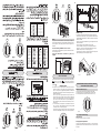
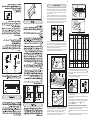
TURNSPIT multilpe
For utilization of the turnspit follow the instructions described.
- Thread the chicken or the cubes of meat for roasting on the
spit L , ensuring that it is gripped safely between the two forks
F and balancing it properly to avoid unnecessary strain on the
trasmission R (fig 6).
- Put the spit on the support G, after having introduced its
opposite end in the socket P of the transmission R (fig 6)
- Put the support G completely into the oven so that the bar I
goes into the socket H of the turnspit motor M (fig 6A).
- Place the drip-tray with some water under the turnspit, on the
lowest level.
- For some models, the turnspit must be used with the oven door
open; in this case, fit the deflector S onto the centring pins N
on the top of the oven opening (fig.5 B ).
- when removing the spit, wear oven mitts, pull out support G
and use the handgrip A operating in the contrary way (fig 6B).
For the functions of the turnspit turning the knob on the position
(fig E) or on the symbol (fig C) when the thermostat is
separate or, in some models, press the marked button with the
symbol .
480 mm
SURFACE BAKING GRILL
(480x240)
240 mm
second
level
S
N
Use of the electric grill with the oven door closed
Some models are designed for the grill to be used with the oven
door completely closed.
In this case the deflector S shown in fig. 5B is not
supplied.
NOTE:
The grill must be used with the door half-open (see fig5 A).
Fit the deflector S onto the centring pins N on the top of the oven
opening (fig.5 B ). Then gently close the oven door against the
deflector.
210
170
140
250
Fig. 7
TURNSPIT single
For utilization of the turnspit follow the instructions described .
- Put the food in spit L (see fig. 7), paying attention to block it within
the two forks F and to balance it, in order to avoid any unnecessary
effort in motor R.
- Put the spit on support G, after having put its opposite end into
hole P of motor R.
- Place the drip-tray with a little water under the spit.
For some models, the turnspit must be used with the oven
door open; in this case, fit the deflector S onto the centring
pins N on the top of the oven opening (fig.5 B ).
- To remote the spit, operate in the opposite direction using knob
S and protecting glove in isolating wool (fig.7).
MINUTES COUNTERS (Fig.8 )
Turn the knob clockwise to set the desired cooking time.
The minutes minder can be adjusted from 1 to 60 minutes.
A sound signal will inform you that the chosen time is up.
USE OF THE TURNSPIT
5
10
15
20
25
35
40
45
50
55
30
Fig. 6 B
A
L
F
R L F
P
G
Fig. 6
Fig. 6 A
I
R
G
M
H
1
2
3
4
5
6
7
8
GB
Fig. 5 A Fig. 5 B
1
2
3
4
5
6
7
8

6 6
XII
XI
X
IX
VIII
VII
VI
V
I
II
III
IV
ELECTRONIC TIMER FOR COOKER (Fig. 9)
Functions
On
The display flashes.
Time setting
Press the left button.
Set the time with buttons “+” and “-”.
This function remains activated 7 seconds after the last +/-
operation.
Timer setting
This function is permanently activated and it will be immediately
set with +/- buttons.
During setting the units are 10 seconds.
During count down the timer takes priority on the display.
The units are seconds.
The maximum time is 99 minutes.
The relay contact (when available) is closed during the count down
only.
Reset timer
Press “+” and “-” buttons together and release “+” button first.
Signal
The signal after time out will stay 7 minutes if it has not been reset
with the “+” button (one touch only).
Signal frequency
When the display shows the time of day, the signal frequency can
be selected by pressing the “-” button. Three different frequencies
are selectable.
Applance type Supply single-phase 230 V~
Type of cable section
Aii gas Rubber H05 RR-F 3 x 0,75 mm
2
All gas + elett. grill Rubber H05 RR-F
S
L
F
R
P
G
L
N
A
GB
ELECTRICAL CONNECTION
REPLACEMENT OF THE CABLE
In case the cable is damaged, replace it in accordance with the
following instructions:
- open the box of the supply board as described on the picture
below;
- unscrew screw “A” fixing the cable;
- replace the cable with one of the same lenght and in accordance
with the features described on the table; switch the appliance
off, and close the gas tap
- the ‘green-yellow” earth wire must be connected to the terminal
“ “ and it must be about 10 mm longer thean the live wires;
- the “blue” neutral wire must be connected to the terminal marked
with letter “N”;
- the live wire must be connected to the terminal marked with letter
“L”.
This appliance must be earthed by law. Before connecting
the appliance to the electrical supply, check that the earth
system in your house is working correctly.
Check that unit voltage and power, marked on the rating plate
applied on the appliance, are correct for the supply. It is necessary
that the feeding network is protected by a powerful switch able to
disconnect completely the network with a contacts separation of
at least 3 mm. Be sure that the earth wire green/yellow is not
interrupted by the switch.
Important: The wires in the mains lead are so coloured:
- green/yellow = earth " "
- blue = neutral “N”
- brown = live “L”
The wire coloured green/yellow must be connected to the terminal
in the plug which is marked with letter 'E' or by the earth symbol
or coloured green or green/yellow. The wire coloured blue must
be connected to the terminal which is marked with letter 'N' or
coloured black. The wire coloured brown must be connected to
the terminal which is marked with letter 'L' or coloured red. The
supply cable must not come into contact with any component the
temperature of which exceeds the ambient temperature by 50°C.
If a plug is used for connection, the plug to be connected to the
supply cable and the socket to which it is connected must be of
the same type (conforming to the standards). Easy access to the
plug or the switch is ensured once the appliance is installed. Ensure
that there is sufficient cable allowed for any subsequent removal
of the unit. If the plug is non-rewireable, pay attention to the
following points: the plug must never be cut by the supply cord.
There is shock hazard when this plug is inserted in a socket-outlet
elsewhere in the house. Never use the plug without the fuse cover
fitted. Referring to the pertinent spare parts, apply to the appliance's
supplier. The manufacturer declines all responsibility for any
damage to persons or things caused by failure to observe
the rules indicated above.
Fig. 9
1 Time of the day
2 Timing and insertion
3 Signal timng and insertion
Connection of the appliance to the power mains should be done
by a licensed electrician familiar with local safety regulations.
3 x 2,5 mm
2
A
L
F
R L F
P
G
I
R
G
M
H
S
N
A
B
E
5
B
5
A
B
5
10
15
20
25
35
40
45
50
55
30

7 7
H05 RR-F
H05 RR-F
XII
XI
X
IX
VIII
VII
VI
V
I
II
III
IV
L
N
A
CARE AND MAINTENANCE
Before cleaning the appliance, disconnect the gas general
tap and unplug the appliance or disconnect power at the
main circuit breaker of the electrical system.
Do not clean the appliance surfaces when still hot.
IMPORTANT
Periodically check the external gas connection hole and
replace it when it shows any sign of deterioration. Do not
attempt to repair the gas hose under any cincumstances.
ENAMELLED SURFACES
Clean with a damp sponge using soap and water.
Grease can be easily removed using hot water or a specific
cleansing agent for enamelled surfaces. Do not use abrasive
cleansers.
Do not leave any acid or alkaline substances (lemon juice, vinegar,
salt, etc.) on the enamel.
Clean the parts in stainless steel with specific cleansers for
stainless steel surfaces.
These detergents must be applied using a soft cloth.
GRIDS AND BURNERS
To clean the work-top burners, remove them by pulling upwards
and soak them for about 10 minutes in hot water with a little
detergent. After having cleaned and washed them, wipe them
carefully.
Make sure that no burner hole is clogged.
Clean the burners once a week or more frequently if necessary.
MAKE SURE YOU HAVE ASSEMBLED THE BURNERS IN A
RIGHT WAY.
A
B C
min. 20mm
min.100 mm
min. 50 mm min. 50 mm
min. 650 mm
min. 400 mm
min. 20mm
GB
WARNINGS
The technical data are indicated on the data nameplate placed
on the rear of the appliance.
The adjustment conditions are stated on the label applied on the
packaging and on the appliance.
Do not use the oven door handle to move the appliance, such as
to remove it from the packaging.
The appliance is in class 1 or class 2 subclass 1.
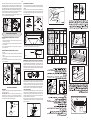
INSTALLATION
IMPORTANT: The coating of the furniture must be able to withstand
high temperatures (min. 90°C).
If the appliance is to be installed near units, leave the minimum
gaps specified in the table below.
OVEN DOOR
For some models, the oven door can be disassembled in the
following way:
hinges A are provided, for this purpose, with two movable jumpers
B; these, once hooked to the hinges slots C, when the door is
completely opened, block them. After that lift the door outward
carring out the two movements shown in the picture. To do that,
operate on the door sides next to the hinges. In order to re-
assemble the door, introduce the hinges in their relevant slots.
Before closing the door, do not forget to remove the movable
jumpers B.
Attention, in proximity of the oven door hinges, there is hurt danger.
OVEN
Clean the enamelled parts with a damp sponge using soap and
water. Grease can be easily removed using hot water or a specific
cleansing agent for enamelled surfaces.
Do not use abrasive cleansers.
INSTRUCTIONS DESTINED TO THE USER
OVERALL DIMENSIONS
895
1450/1500
610
100
850/900
910/960
895895
The cooker is fitted with 4 legs for an eventual alignment in height
with the furniture. To assemble them, it is necessary to raise the
cooker and to screw the four legs into the suitable threadings
placed on the corners on the bottom of the appliance .
N

8 8
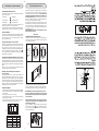
GAS CONNECTION
ROOMS VENTILATION
A
B C
GAS APPLIANCES
This appliance is not connected to a device to vent the combustion
products. It must therefore be installed and connected in conformity
with the installation standards in force.
Particular attention must be paid to the standards on ventilation
of the room.
VENTILATION OF ROOMS
Remember that this appliance can be installed and work in well-
ventilated rooms only, according to the standards in force, such
as to allow, with openings on the external walls or with special
ducts, a correct natural or forced ventilation ensuring permanently
and sufficiently both the entry of the air needed for correct
combustion and the removal of spent air.
In particular when there is only this gas appliance in the room,
there must be a hood over the appliance to ensure the natural and
direct removal of spent air, with a vertical straight duct of length
equal to at least twice the diameter and a minimum section of at
least 100 cm
2
.
For the indispensable entry of fresh air into the room there must
be a similar 100 cm
2
opening directly to the outside, situated at
a height near floor level so that it is not blocked either inside or
outside the wall and so as not to cause disturbances to correct
burners combustion and to the regular removal of spent air and
with a difference of height with respect to the outlet opening of at
least 180 cm.
Remember that the quantity of air necessary for combustion must
never be less than 2m
3
/h for each kW of power (see total power
in kW on the appliance data plate).
In all other cases, i.e. when there are other gas appliances in the
same room, or when natural direct ventilation is not possible and
natural indirect or forced ventilation must be installed, contact a
qualified specialist who will install and make the ventilation system,
scrupulously observing the regulations contained in the standards
in force.
The openings must be so positioned that there are no draughts
of air which cannot be tolerated by the occupants.
Moreover to eliminate combustion products, it is forbidden to use
flues already used by other appliances.
The appliance must be connected to the gas piping in a workmanlike
way and in conformity with the regulations in force which lay down
the installation of a safety valve at the end of the piping.
For butane and propane a pressure reducer conforming to the
standards in force may perform this task.
The seal gaskets must be in accordance with rules.
Once the gas appliance has been connected, check the connection
seal by means of soapy water.
The end of the attachment is threaded.
The possible connections are:
If the connecting tube must be passed behind the appliance,
observe the regulations of the picture, making sure in the last case
that the tube is kept in support A.
- by rigid pipe in iron or copper
- by flexible tube in stainless steel with continuing wall, with
mechanical connection in accordance with rules. The tube must
be directly connected to the manifold elbow (see Fig.34).
- by the insertion of a rubber tube in accordance with rules.
This tube must be connected directly on the push-on connector,
concerning the gas used, and it must be blocked with a band.
In the last case, check the tube's printed date of expiry and
replace it before this date.
WARNINGS
Concerning rubber flexible tubes (max. length 1500 mm), we
remember you:
1 - to avoid the tube to be narrowed or crushed
2 - do not submit it to traction or torsion efforts
3 - to avoid contact with sharp edges, etc...
4 - to avoid contact with parts reaching temperatures over 70°C
the ambient temperature
5 - to ensure that they can be checked for all their length.
min. 180 cm.
min. 100cm
2
.
min. 180 cm.
electrical fan
min. 100cm
2
. min. 100cm
2
.
We recommend to check wether the appliance has been foreseen
for the kind of gas distributed.
F
HOSE
ATTACHMENT
FOR LIQUID
GAS
HOSE
ATTACHMENT
FOR NATURAL
GAS
Fig. 10
F
1/2”
GB
895895
c
INLET STOP

9 9
F
GAS ADJUSTMENT
C
GB
A B
Unscrew the adjusting screw in order to increase the flow or screw
it to decrease the flow.
The right adjustment is obtained when the flame has a length of
about 3 or 4 mm.
For butane/propane gas, the adjusting screw must be tight screwed.
Make sure that the flame does not go out passing quickly from
the max. flow to the minimum flow and viceversa .
Assemble the knob again.
MINIMUM FLOW ADJUSTMENT FOR OVEN THERMOSTAT
In order to adjust the minimum, act as follows: switch the burner
on turning the knob to the maximum position.
Remove the knob and unscrew of some turns the by-pass screw
(fig. H).
Assemble the knob and let the oven warm up for 15 minutes; after
that turn the knob to the minimum position.
Fig. 11
Fig. 12
Z
If the appliance is foreseen to operate with a type of gas different
from the suitable supply gas, proceed as follows: change the
injectors, adjust the minimum flow of the burners, change the
push-on connector.
In order to change the work-top injectors, it is necessary to act as
follows: remove the grids, remove burners and flame-spreaders
(see fig.A), change the injector (see fig.B) and replace it with
another one suitable for the new type of gas (see table D). Re-
assemble everything in the opposite direction, paying attention to
place the flame-spreader in the right way on the burner.
To change the oven injector, it is necessary to act as follows: open
the oven door, remove the lower side of the oven (see fig.C),
unscrew screw C and disassemble the oven burner (see fig.D).
Change the injector (see fig.E) and replace it with another one
suitable for the new gas type (see table D).
Re-assemble everything in the opposite direction, paying attention
to place the burner in the right way on its rear slot.
To change the grill injector, it is necessary to act as follows: open
the oven door, unscrew screw C and disassemble the grill burner
(see fig.F). Change the injector (see fig.G) and replace it with
another one suitable for the new gas type (see table D).
Re-assemble everything in the opposite direction, paying attention
to place the burner in the right way on its rear slot.
MINIMUM FLOW ADJUSTMENT FOR WORK-TOP TAPS
In order to adjust the minimum, act as follows: switch the burner
on, and turn the knob towards the minimum flow position .
Remove the knob from the tap, introduce a little screwdriver in the
tap rod (fig. 11).
Attention: in taps with security valve, the minimum adjusting screw
“Z” is placed outside the rod tap (fig. 12).
FIG.E
FIG.C
FIG.D
FIG.G
F
¦
"
FIG.F
C
TAB. D GENERAL INJECTORS TABLE
Kind of gas mbar Nozzle Burners Power Watt Consum.
N. Position-type max. min. max.
1.15 Rapide 3000 750 286 l/h
NATURAL 20 0.97 Semi rapide 1750 480 167 l/h
0.72 Auxiliary 1000 330 95 l/h
1.28 Triple crown 3300 1300 315 l/h
1.45 UltraRapide 3600 1500 343 l/h
1.20 Fish 2900 1500 277 l/h
1.50 Oven 4300 389 l/h
1.45 Grill 3800 344 l/h
G.P.L. 30 0.85 Rapide 3000 750 219 g/h
BUTANE 28 0.65 Semi rapide 1750 480 128 g/h
PROPANE 37 0.50 Auxiliary 1000 330 73 g/h
0.93 Triple crown 3300 1300 241 g/h
0.96 UltraRapide 3600 1500 262 g/h
0.85 Fish 2900 1500 211 g/h
1.00 Oven 4300 313 g/h
0.95 Grill 2800 277 g/h
NATURAL 20 1.25 Grill 2800 253 l/h
G.P.L. 30 0.75 Grill 2800 204 g/h
BUTANE 28
PROPANE 37
with separated thermostat

10 10
A
A
APPLIANCE MAINTENANCE
Fig. L Fig. M
C
GB
After having removed the knob once again, making sure that the
thermostat rod has not been moved, screw slightly the above
mentioned by-pass screw, to obtain a flame of 3 or 4 mm of length.
For butane/propane gas, the adjusting screw must be tight screwed.
Make sure that the flame does not extinguish passing quickly from
the maximum flow to the minimum flow, and closing and opening
the oven door (the oven door must be closed softly).
Attention: for taps with safety device, the minimum adjusting screw
“T” is on the outside of the tap rod (fig. I ).
E 14
25 W - 230 V~
T300°C
A
WARNINGS
Isolate the cooker from the electricity supply before attempting to
replace the oven lamp.
The oven lamp used is of a special type withstanding high
temperatures. To replace it, act as follows: disassemble the
protecting glass (A) and replace the burnt lamp with one of the
same type. Reassemble the protecting glass.
DISASSEMBLE OF WORK-TOP
In case it is necessary to repair or replace the inside components,
act as follows:remove the glass lid from its position slipping off it
upwards.
Remove the grids, remove burners and flame-spreaders (see
fig. 13), unscrew the visible screws “V” placed on the work-top
(see fig. 14). Disassemble the work-top by unscrewing the 4 rear
screws “A” (see fig. 15 ).
REGULATION OF AIR ADJUSTER (oven burner )
To do this,
- Unscrews the screw (A ) in order to rotate the metal ring at the
end of the burner (fig L ).
In this way, entrace of the air increases or descreases, obtaining
a correct flame.
Be sure that the flame does not lift or light back or present a
yellow colouration .
REGULATION OF AIR ADJUSTER (grill burner )
To do this,
- Unscrews the screw (A ) in order to slip it forwards or backwards
(fig M).
In this way, entrace of the air increases or descreases, obtaining
a correct flame.
Be sure that the flame does not lift or light back or present a
yellow colouration .
Fig. H
T
Fig. I
REGULATION AIR ADJUSTER
Fig. 14
V
Fig. 13
A
Fig. 15
Clean the cone and its slot by means of a cloth soaked with diluent.
Slightly grease the cone with the relevant grease, put it in its slot,
and turn it some times. Remove the cone again, remove the
exceeding grease making sure the gas entries are not obstructed
by grease residuals. Assemble everything carefully in the opposite
direction check the connection seal by means of soapy water.
TAPS REPLACEMENT
Act as follows: switch the appliance off, and close the general tap
open the work-top and disassemble also the control panel as
described on the previous paragraph. Unscrew screw nut D of the
gas tube supplying the burner. Unscrew screw V fixing the tap to
the bridle and remove it (see picture).
Note: Every time the tap is replaced, it is necessary to replace the
seal gasket too check the connection seal by means of soapy
water (see picture).
- To disassemble the control panel, unscrew the 4 internal screws
(B) fixing the control panel to the oven face ( fig 16 ).
GREASING OF TAPS
WARNING:This operation must be carried out by skilled staff.
If a tap becomes hard to be turned, grease it using a specific
grease withstanding high temperatures. Act as follows: switch the
appliance off, and close the gas tap open the work-top and
disassemble also the control panel as described on the previous
paragraph. Unscrew the two fixing screws from the burner body
(see picture) and remove the cone.
Fig. 16
B
D
V
15
7
A B
Z
C

11 11
A
A
T
H
RENSEIGNEMENTS GENERAUX
DESTINES A L’UTILISATEUR
Ce produit répond aux éxigences des Directives Communautaires:
- 73/23/CEE relative à la "basse tension".
- 89/336/CEE relative aux "perturbations électromagnétiques".
- 90/396/CEE relative aux “appareils à gaz”
- 89/109/CEE relative aux “matériaux en contact avec les aliments".
- En plus les Directives sur mentionnées sont conformes à la
Directive 93/68/CEE.
- Cet appareil devra être exclusivement destiné à l'usage pour
lequel il a été expressément projeté, en tant “qu'appareil de
cuisson” domestique.
CHER CLIENT,
• Nous Vous invitons à lire attentivement ces instructions avant
d'utiliser l'appareil et de les conserver soigneusement afin de
les consulter en cas de besoin.
• Le matériel d'emballage (sacs en plastique, morceaux de
polystyrène, etc...) doit être tenu hors de portée des enfants car
il constitue une source potentielle de danger.
GARANTIE
Votre nouvel appareil est couvert par une garantie.
Le certificat relatif se trouve ci-joint.
S'il manque, demandez-le à Votre revendeur, en spécifiant la date
d'achat, le modèle et le numéro matricule imprimés sur la plaquette
d'identification de l'appareil.
Conservez la partie qui Vous est destinée. Celle-ci doit être
montrée, en cas de nécessité, au personnel du Service Assistance
Technique avec la relative facture d'achat.
Si Vous ne suivez pas cette procédure, le personnel technique
sera obligé de Vous débiter toutes les éventuelles réparations.
SERVICE ASSISTANCE TECHNIQUE
Cet appareil, avant de sortir de l’usine, a été essayé et réglé par
du personnel expert et spécialisé, afin de pouvoir donner les
meilleurs résultats de fonctionnement.
Toute réparation ou mise au point, qui pourrait ensuite se rendre
nécessaire, doit être effectuée avec le plus grand soin et beaucoup
d’attention.
Pour cette raison, nous conseillons de Vous adresser toujours au
revendeur ou à notre Centre Assistance plus proche, en spécifiant
le type d’incovénient et le modèle de Votre appareil.
CONSEILS ET AVERTISSEMENTS
D’ORDRE GENERAL
ATTENTION:
- N'oubliez pas, avant d'utiliser l'appareil, d'enlever le film de
plastique qui protège certaines pièces (tableau de bord, cadres
en inox, etc).
- Ne pas utiliser l'appareil pour chauffer la pièce.
- Lorsque l'appareil n'est pas utilisé, débrancher le courant et
fermer le robinet général du gaz.
EN CAS D'INCENDIE
• En cas d'incendie, fermer le robinet général d'alimentation
et couper le courant; ne jamais jeter de l'eau sur l'huile en
flamme ou en train de frire.
• Ne pas garder de produits infammables ou de bouteilles d'aérosol
près de l'appareil et ne pas vaporiser d'aérosol près d'un brûleur
allumé.
POUR VOTRE SURETE ET CELLE DE VOS ENFANTS.
• Eviter de garder dessus ou près de l'appareil des produits
attractifs pour les enfants.
• Garder les enfants loin de l'appareil: ne pas oublier que certaines
parties de l'appareil ou des casseroles utilisées deviennent très
chaudes et dangereuses tant pendant le fonctionnement que
pendant le temps nécessaire au refroidissement après l'extinction.
• Faire attention aux poignées des casseroles, disposez-les de
façon que les jeunes enfants ne fassent pas tomber les
casseroles.
• Ne mettez pas de vêtements ou d'accessoires amples lorsque
les brûleurs sont allumés; l'incendie du textile peut être cause
de graves blessures.
ATTENTION - FOUR:
Lorsque le four ou le grilloir sont en fonction, les parties
accessibles peuvent devenir très chaudes, il faut éloigner les
jeunes enfants de l'appareil.
- Eviter de cuire les aliments sur la base du four.
- En cas d'utilisation négligente en proximité des charnières de
la porte du four, il existe le danger de se blesser les mains.
- Interdir aux enfants de s’asseoir ou de jouer avec la porte du
four. Ne pas utiliser la porte comme un tabouret.
TIROIR INFERIEUR
N’introduisez pas de matériaux inflammables ou en plastique dans
le chauffe-plats (positionné au dessous du four).
Recommandations
(Pour les cuisinières avec le couvercle en verre)
Le couvercle en verre pendant l’utilisation ne doit pas être en
contact avec les casseroles et après l’utilisation ne doit pas être
ferme avec les brûleurs ou les plaques encore chauds.
AVERTISSEMENTS POUR L'ENVIRONNEMENT
Déchets emballage
Ne pas jeter l'emballage de Votre appareil aux ordures, mais
sélectionnez les différents matériaux (par ex. tôle, carton,
polystyrène) selon les prescriptions locales pour l'élimination
des déchets.
FR
V
A
A
A

12 12
Brûleurs Ø min Ø max
-Rapide 180mm 320mm
-Semirapide 120mm 220mm
-Auxiliaire 80mm 180mm
-Triple couron 220mm 320mm
-Ultrarapide 220mm 320mm
Quand le four est utilisé pour la première fois, il peut se produire
de la fumée de odeur âcre, causée par le premier chauffage du
collant des panneaux isolants autour du four (il est opportun de
le chauffer à la température maximale pour une durée de 30-
40 minutes à porte fermée). Il s’agit d’un phénomène absoluement
normal et, s’il devait se produire encore, il faudrait attendre que
la fumée cesse avant d’introduire les aliments.
En général le four est équipé de: grille support pour la cuisson
des préparations en casseroles ou bien posées directement sur
la grille, lèche-frite pour la cuisson des gâteaux, biscuits, etc. ou
pour récupérer les jus et les matières grasses des aliments placés
directement sur la grille.
AVERTISSEMENTS: éviter de cuire les aliments sur la sole
positionnée à la base du four.
FOUR A GAZ
ALLUMAGE MANUEL DU BRÛLEUR FOUR
Pour allumer le brûleur du four, introduire une allumette dans
l'orifice (fig. 2) et ouvrir ensuite le robinet en position maximum
comme indiqué sur la figure 1.
UTILISATION DE LA TABLE DE TRAVAIL
UTILISATION DES BRÛLEURS A GAZ
Les symboles suivants se trouvent sur le bandeau de commande,
près de chaque bouton:
- Disque plein robinet fermé
- Grande flamme ouverture maximale
- Petite flamme ouverture minimale
La position de minimum se trouve à la fin de la rotation en sens
inverse des aiguilles d'un montre de la manette.
Toutes les positions de fonctionnement doivent être choisies entre
les positions de max. et de min., jamais entre max. et la fermeture.
ALLUMAGE MANUEL
Pour allumer l'un des brûleurs, approcher une allumette au brûleur,
presser le bouton correspondant au brûleur préalablement choisi
et le tourner dans le sens inverse des aiguilles d'une montre
jusqu'à la position de max.
ALLUMAGE ELECTRIQUE (selon les modèles)
Pour allumer l'un des brûleurs, presser le bouton correspondant
au brûleur préalablement choisi et le tourner dans le sens inverse
des aiguilles d'une montre jusqu'à la position de max;
simultanément, actionner le bouton-poussoir de l'allumage électrique
placé sur le tableau de bord et portant le symbole . Dans le cas
où il n'y aurait plus de courant électrique, le brûleur pourra être
allumé à l'aide d'une allumette.
ALLUMAGE ELECTRIQUE AUTOMATIQUE (selon les modèles)
Pour allumer l'un des brûleurs, presser le bouton correspondant
au brûleur préalablement choisi et le tourner dans le sens inverse
des aiguilles d'une montre jusqu'à la position de max. En maintenant
pressée la manette on mettra en fonction l'allumage électrique du
brûleur.
Dans le cas où il n'y aurait plus de courant électrique, le brûleur
pourra être allumé à l'aide d'une allumette.
APPAREILS AVEC THERMOCOUPLE DE SECURITE
(selon les modèles)
Pour l'allumage des brûleurs, il est nécessaire d'effectuer les
mêmes opérations décrites ci-dessus. Dans ce cas, une fois que
les manettes se trouvent en position d'ouverture, il est indispensable
de continuer à appuyer sur la manette concernée pendant environ
10 secondes après l'allumage. Si la flamme devait s'éteindre une
fois que Vous relâchez la manette, le dispositif de sécurité bloquera
le passage du gaz vers le brûleur concerné.
ECONOMIE D'ENERGIE
• Le diamètre du fond de la casserole doit correspondre au diamètre
du brûleur. La flamme du brûleur ne doit jamais sortir du diamètre
de la casserole.
• Utiliser toujours des casseroles à fond plat.
• Cuire de préférence avec un couvercle. Cela permet d'utiliser
des puissances plus basses.
• Cuire les légumes, pommes de terre, etc. avec peu d'eau pour
économiser l'énergie et réduire les temps de cuisson.
Fig.1
UTILISATION DU FOUR A GAZ
Allumage électrique du brûleur du four (selon les modèles).
La porte du four doit toujours être complètement ouverte,
avant l’allumage du brûleur.
Tourner la manette vers la gauche jusqu’à la position maximale,
puis appuyer sur le bouton jusqu’à l’allumage du brûleur.
En cas de coupure électrique, les brûleurs peuvent être allumés
avec des allumettes.(fig 2).
210
170
140
250
1
2
3
4
5
6
7
8
Pos.1 : 140°C
Pos.8 : 250°C
= FERME
= MINIMALE
= MAXIMALE
= GRILLOIR
FR
Après s'être assuré que le brûleur est bien allumé, fermer
doucement la porte du four. Pour obtenir la température désirée,
faire correspondre le numéro choisi avec l'index de la manette .
ATTENTION:Ne pas actionner l'allumage pour plus de 15
secondes. Si le brûleur ne s'allume pas, presser de nouveau
la manette après avoir laissé la porte du four ouverte pendant
au moins 1 minute.
Fig. 3
Fig. 1
Fig. 2
15
7
D
V
-
 1
1
-
 2
2
-
 3
3
-
 4
4
-
 5
5
-
 6
6
-
 7
7
-
 8
8
-
 9
9
-
 10
10
-
 11
11


AEG C9500G-CMI Manuel utilisateur
- Taper
- Manuel utilisateur
- Ce manuel convient également à
dans d''autres langues
- English: AEG C9500G-CMI User manual