Faber Stratus 36 SS Guide d'installation
- Catégorie
- Hottes
- Taper
- Guide d'installation
Ce manuel convient également à

Installation Instructions
Use and Care Information
Instructions d'installation
Utilisez et d'entretien
Instrucciones de instalación
Información de uso y cuidado
STRATUS NB
STRTIS48SSNB
STRTIS36SSNB

2

3
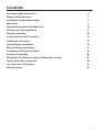
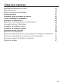
Contents
Important Safety Instructions 4
Range hood Dimensions 7
Installation Height Requirements 7
Main Parts 8
Combinations Hoods And Motor Kits 10
Choose Your Ducting Method 11
Wiring Preparation 12
Ceiling Hood Install Preparation 13
Installation Information 14
Internal Blower Installation 15
External Blower Installation 17
Installation of Range Hood Body 20
Connect The Ducting 26
Wiring Box 2 Connection (Remote Blower Wiring Only) 27
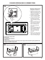
House Wiring Box Connection 28
Use and Care Information 30
Wiring Diagram 33

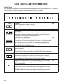
4
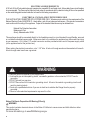
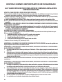
READ AND SAVE THESE INSTRUCTIONS BEFORE YOU START INSTALLING
THIS RANGE HOOD
WARNING: - TO REDUCE THE RISK OF A RANGE TOP GREASE FIRE:
a) Never leave surface units unattended at high settings. Boilovers cause smoking and greasy spillovers that
may ignite. Heat oils slowly on low or medium setting.
b)AlwaysturnhoodONwhencookingathighheatorwhenambeingfood(i.e.CrepesSuzette,Cherries
Jubilee,PeppercornBeefFlambé).
c)Cleanventilatingfansfrequently.Greaseshouldnotbeallowedtoaccumulateonfanorlter.
d)Useproperpansize.Alwaysusecookwareappropriateforthesizeofthesurfaceelement.
WARNING: - TO REDUCE THE RISK OF INJURY TO PERSONS IN THE EVENT OF A RANGE TOP GREASE
FIRE,OBSERVETHEFOLLOWING*:
a)SMOTHERFLAMESwithaclose-ttinglid,cookiesheet,ormetaltray,thenturnofftheburner.BECAREFULTO
PREVENTBURNS.IftheamesdonotgooutimmediatelyEVACUATEANDCALLTHEFIREDEPARTMENT.
b) NEVER PICK UP A FLAMING PAN - You may be burned.
c)DONOTUSEWATER,includingwetdishclothsortowels-aviolentsteamexplosionwillresult.
d)UseanextinguisherONLYif:
1. YouknowyouhaveaClassABCextinguisher,andyoualreadyknowhowtooperateit.
2. Thereissmallandcontainedintheareawhereitstarted.
3. Theredepartmentisbeingcalled.
4. Youcanghttherewithyourbacktoanexit.
* Based on "Kitchen Firesafety Tips" published by NFPA
WARNING-TOREDUCETHERISKOFFIREORELECTRICSHOCK,donotusethisfanwithanysolid-
state speed control device.
WARNING-TOREDUCETHERISKOFFIRE,ELECTRICALSHOCK,ORINJURYTOPERSONS,OBSERVE
THE FOLLOWING:
1. Usethisunitonlyinthemannerintendedbythemanufacturer.Ifyouhaveanyquestions,contact
the manufacturer.
2. Beforeservicingorcleaningunit,switchpoweroffatservicepanelandlocktheservicedisconnecting
means to prevent power from being switched on accidentally. When the service disconnecting means
cannotbelocked,securelyfastenaprominentwarningdevice,suchasatag,totheservicepanel.
CAUTION:ForGeneralVentilatingUseOnly.DoNotUseToExhaustHazardousorExplosiveMaterials
and Vapors.
WARNING-TOREDUCETHERISKOFFIRE,ELECTRICALSHOCK,ORINJURYTOPERSONS,OBSERVE
THE FOLLOWING:
1. InstallationWorkAndElectricalWiringMustBeDoneByQualiedPerson(s)InAccordanceWithAll
ApplicableCodesAndStandards,IncludingFire-RatedConstruction.
2. Sufcientairisneededforpropercombustionandexhaustingofgasesthroughtheue(chimney)of
fuel burning equipment to prevent backdrafting. Follow the heating equipment manufacturer's guideline
andsafetystandardssuchasthosepublishedbytheNationalFireProtectionAssociation(NFPA),and
theAmericanSocietyforHeating,RefrigerationandAirConditioningEngineers(ASHRAE),andthe
local code authorities.
3. Whencuttingordrillingintowallorceiling,donotdamageelectricalwiringandotherhiddenutilities.
4. Ducted fans must always be vented to the outdoors.
IMPORTANT SAFETY INSTRUCTIONS

5
ALL WALL AND FLOOR OPENINGS WHERE THE RANGE HOOD IS INSTALLED MUST BE SEALED.
This Range Hood requires at least 35" of clearance between the bottom of the Range Hood and the cooking
surface or countertop. This hood has been approved by UL at this distance from the cooktop.
Consult the cooktop or range installation instructions given by the manufacturer before making any cutouts.
MOBILE HOME INSTALLATION The installation of this Range Hood must conform to the Manufactured
Home Construction and Safety Standards, Title 24 CFR, Part 3280 (formerly Federal Standard for Mobile Home
Construction and Safety, Title 24, HUD, Part 280).
Attention: This hood has been engineered to minimize electromagnetic interference (EMI) originating
from the consumer's home power source. However, in some home application, ambient EMI and
excessive EMI from other electronic sources can compromise the reliability of the remote control.
Please speak with your Faber Distributor about an optional spare part to further reduce EMI from
home sources.
• Venting system MUST terminate outside the home.
• DO NOT terminate the ductwork in an attic or other enclosed space.
• DO NOT use 4" laundry-type wall caps.
• Flexible-type ductwork is not recommended.
• DO NOT obstruct the ow of combustion and ventilation air.
• Failure to follow venting requirements may result in a re.
WARNING
!
VENTING REQUIREMENTS
Determine which venting method is best for your application. Ductwork can extend either through the wall or the roof.
The length of the ductwork and the number of elbows should be kept to a minimum to provide efcient performance. The
size of the ductwork should be uniform. Do not install two elbows together. Use duct tape to seal all joints in the ductwork
system. Use caulking to seal exterior walls and ceiling space opening around the cap.
Flexible ductwork is not recommended. Flexible ductwork creates back pressure and air turbulence
that greatly reduces performance.
Make sure there is proper clearance within the walls and ceiling space for exhaust duct before making cutouts. Do not
cut a joist or stud unless absolutely necessary. If a joist or stud must be cut, then a supporting frame must be constructed.
WARNING - To Reduce The Risk Of Fire, Use Only Metal Ductwork.
CAUTION-Toreduceriskofreandtoproperlyexhaustair,besuretoductairoutside–Donotventexhaustair
intospaceswithinwallsorceilingsorintoattics,crawlspaces,orgarages.
Cold Weather installations
An additional back draft damper should be installed to minimize backward cold air ow and a nonmetal-
lic thermal break should be installed to minimize conduction of outside temperatures as part of the vent
system. The damper should be on the cold air side of the thermal break. The break should be as close as
possible to where the vent system enters the heated portion of the house.

6
ELECTRICAL REQUIREMENTS
A 120 volt, 60 Hz AC-only electrical supply is required on a separate 15 amp fused circuit. A time-delay fuse or circuit breaker
is recommended. The fuse must be sized per local codes in accordance with the electrical rating of this unit as specied
on the serial/rating plate located inside the unit near the eld wiring compartment.
ELECTRICAL INSTALLATION WITH WIRING BOX
THIS UNIT MUST BE CONNECTED WITH COPPER WIRE ONLY. Wire sizes must conform to the requirements of the
National Electrical Code, ANSI/NFPA 70 - latest edition, and all local codes and ordinances. Wire size and connections
must conform with the rating of the appliance. Copies of the standard listed above may be obtained from:
National Fire Protection Association
Batterymarch Park
Quincy, Massachusetts 02269
This appliance should be connected directly to the fused disconnect (or circuit breaker) through exible, armored
or nonmetallic sheathed copper cable. Allow some slack in the cable so the appliance can be moved if servicing
is ever necessary. A UL Listed, 1/2" conduit connector must be provided at each end of the power supply cable
(at the appliance and at the junction box).
When making the electrical connection, cut a 1 1/4" hole. A hole cut through wood must be sanded until smooth.
A hole through metal must have a grommet.
• Electrical ground is required on this Range Hood.
• If cold water pipe is interrupted by plastic, nonmetallic gaskets or other materials, DO NOT use for
grounding.
• DO NOT ground to a gas pipe.
• DO NOT have a fuse in the neutral or grounding circuit. A fuse in the neutral or grounding circuit could
result in electrical shock.
• Check with a qualied electrician if you are in doubt as to whether the Range Hood is properly
grounded.
• Failure to follow electrical requirements may result in a re.
WARNING
!
StateofCaliforniaProposition65Warning(USonly)
WARNING
This product contains chemicals known to the State of California to cause cancer and birth defects or other
reproductive harm.
For more information go to www.P65Warnings.ca.gov

7
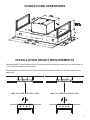
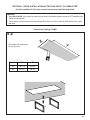
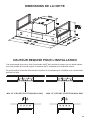
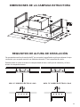
RANGE HOOD DIMENSIONS
INSTALLATION HEIGHT REQUIREMENTS
Recommended 60" mounting height above the cooking surface for best performance, but can be mounted up
to 72" maximum away the cooking surface.
An access point to the hood from the ceiling or soft must be made for installation and future access to the
range hood.
MAX. 72" OVER ELECTRIC / GAS
MIN. 35" OVER ELECTRIC / GAS

8
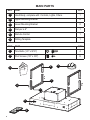
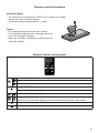
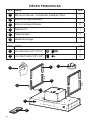
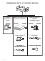
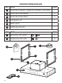
MAIN PARTS
REF. PART QTY
A
Hood Body, complete with: Controls, Lights, Filters. 1
B
Upper Mounting Bracket 2
C
Lower Mounting Bracket 2
D
Damper ø 6" 1
E
Remote Control 1
H
Drilling Template 1
REF
PART
QTY
F
Torx Bolts (1/4" x 9/16")
4
G
Pozi Screws (1/8" x 3/8")
8
D
E
A
B
C
F
G
H
8
AA-725973-1
1x
1x
C
1x
B
A
1x
3x 4x
1x
D E
1x
1x
1x
1x

9
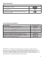
CAUTION - To Reduce The Risk Of Fire And Electric Shock, Install This Range Hood Only With
Remote Blower Models RB900 kit or RB1200 kit Manufactured by Faber Or Integral Blowers
Manufactured by Faber, Model(s) IB600 kit, IB400 kit, IB300 kit or generic remote blower rated max
2.7A suitable for use with solid state speed control.
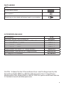
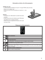
PARTS NEEDED
PART
6" Round Metal Ductwork
Wire connectors.
Drywall plugs or other suitable wall fasteners based on your installation.
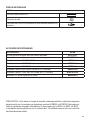
ACCESSORIES AVAILABLE
ACCESSORY SKU#
Activated Charcoal Filter Accessory Kit #FILTER1
Washable Long-Lasting Activated Charcoal Filter Kit #FILTER1LL
Internal 600 PRO Blower IB600 #IB600 kit
Internal 400 Blower IB400 #IB400 kit
Internal 300 Blower IB300 #IB300 kit
Remote Blower 900 RB900 (10” Flange Included) #RB900 kit
Remote Blower 1200 RB1200 (10” Flange Included) #RB1200 kit
10" Flange for In-Line Blower #FLANGE10

10
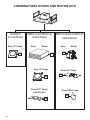
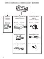
COMBINATIONS HOODS AND MOTOR KITS
RB900 kit and RB1200 kit
(remote blower)
FLANGE10
(In-Line Blower)
IB600 kit, IB400 kit, IB300 kit
(internal blower)
3B
4B
Discard 6" Flange
Discard 10" Flange
withWireBox
Discard Wire Cable
Version 07/11 - Page 6
INSTALLATION
COMBINATIONS HOOD AND MOTOR KITS
CHOOSE A BLOWER FOR YOUR HOOD
After choosing the hood width and depth for your cooking
needs, next choose the type of blower appropriate for
your cooking.
NOTE: no other blower is
compatible with this hood, except for the
kits below.
# IB300 - Internal Blower Kit 300 cfm
# IB600 - Internal Blower Kit 600 cfm
# IB1200 - Internal Blower Kit 1200 cfm
# RB900 - Remote Blower Kit 900 cfm
# RB1200 - Remote Blower Kit 1200 cfm
# INLBKIT - In Line Blower Kit
(supply own in-line blower)
OPTIONAL ACCESSORIES AVAILABLE
• *Charcoal Filter
* it is highly recommended that professional style cooking always be
vented to the outside; for recirculating installations only, some ductwork is
required to exhaust the unit out of the cabinet. Replace as needed with the
same model
part # FILTER1
NOTE: The charcoal filter kit for use with the 300 / 600
cfm internal blower kit ONLY
CAUTION - To reduce risk of fire and electric shock, install this rangehood only with: Remote blower manufacturer by Faber
models RB900 and RB1200 or Integral blower manufactured by Faber models IB300 or IB600 or IB1200 or with INLBKIT and
generic in-line blower rated max 4.2 A suitable for use with solid state variable speed control
INLBKIT
1A
Keep
Keep 10" Flange
Blower
1B
Keep Blower
3A
2A
Keep 10" Flange
2A

11
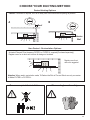
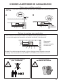
Non Ducted - Recirculation Options
Ducted Venting Options
Activated Charcoal Filter Accessory FILTER1 or FILTER1LL required (Purchased separately).
Register cover for air duct exit is shown for design not included.
Attention: When used in recirculation mode, To Reduce the Risk of Fire and Shock use only conversion
kit Model FILTER1 or FILTER1LL.
6 "
A B
Register cover for air
duct exit is suggested.
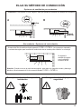
CHOOSE YOUR DUCTING METHOD
Two men required for installation Wear work gloves for safety
Caution: If an elbow is required, do it as far away from the hood's exhaust opening as possible
6 "
Roof
Exterior
Wall

12
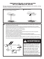
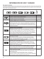
Open the lter cover panel. The lter cover panel
is held by a magnet catch, pull down with enough
force to release as shown below.
Remove the grease lters one at a time, pushing
them towards the back of the unit, and at the
same time pulling downward and set aside.
1 2
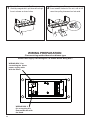
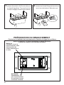
WIRING PREPARATION
WIRING BOX 1 for
connecting the Home
power supply cable
with the Hood.
WIRING BOX 2
for connecting the
External Blower with
the Hood.
HousePowerSupplyCableWiringBox1&RemoteBlowerWiringBox2
Choose wiring method based on blower type
1
2
3
1
2

13
3
Do not make any cutouts until you have decided whether this installation will be: ducted or non-ducted
and wiring has been prepared based on based on blower type.
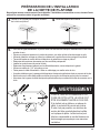
CEILING HOOD INSTALL PREPARATION
Use a plumb line to mark the center of the
range on the ceiling.
Mark the centers.
4
5
DUE TO THE SIZE AND WEIGHT OF
THIS Range Hood, THE SUPPORT
MUST BE FIRMLY ATTACHED TO
THE CEILING. For plaster or sheet
rock ceiling, the support must be
attached to the joists. If this is not pos-
sible, a support structure must be built
behind the plaster or sheet rock. The
manufacturer assumes no responsibil-
ity for injury or damage caused by
improper installations.
WARNING
!
• For all installations, an access point to the hood must be created for installation and future maintenance
of the hood.
• Put a thick, protective covering over cooktop to protect from damage or dirt.
• Use the mounting template on the ceiling to determine placement of mounting screws on the ceiling.
• Mark the center of the holes in the ceiling template.
• Determine and make necessary cuts for the ductwork.
• Install ductwork before mounting the hood.
• Determine the proper location for the Power Supply Cable as indicated on the Template.
• Use a 1 1/4" Drill Bit to make this hole.
• Run the Power Supply Cable. Use caulking to seal around the hole.
• A knockout for threading through the Power Supply from the ceiling is located on the top of the Range
Hood.
• Do not connect the Power Cable to the Wiring Box or power up the hood at this time.
• Run enough power cable from the ceiling to reach the wiring box on the hood.
1 1/4"
H

14
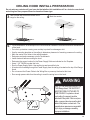
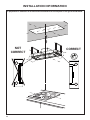
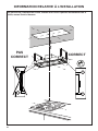
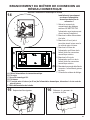
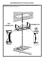
CORRECT
NOT
CORRECT
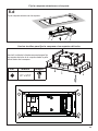
In preparation for installation of the hood orient the hood with the control panel on the right as shown below
INSTALLATION INFORMATION
$[
PP
[
[

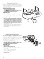
15
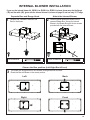
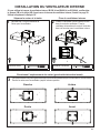
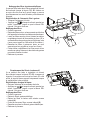
1
3
Unfasten the 4 screws to dismount the
Box for the blower.
The blower can be positioned in four different venting directions as shown.
Rotate the Box with Blower in the correct position.
2
Position Internal Blower as shown into the
removed Blower Box. Secure the Internal
Blower in the Blower Box with the two screws
provided with the Internal Blower.
INTERNAL BLOWER INSTALLATION
Left
Right
Back
Front
Separate Box and Range Hood
Choose the Box position (Left-Right-Back-Front)
Attach the Internal Blower
Phillips ScrewdriverTorx Screwdriver
lfyouusetheinternalblowerkit,IB600kitorIB400kitorIB300kit,pleasethrowawaythetheange
(3B)andthecable(4B),givenwiththeinternalblowerkit,shownonpage10anduseonly10”Flange.

16
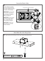
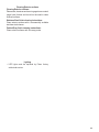
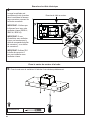
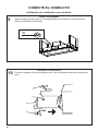
4
Attach the Box with the Blower with the same 4 screws removed previously.
After the blower is mounted
in the hood, plug the harness
with molex originating from the
control box, into the blower.
IMPORTANT: Do not use the
harness that came with your
internal blower kit (IB600 kit,
IB400 kit, IB300 kit).
IMPORTANT: Do not connect
the Control Cable to Wiring
Box 1 or Wiring Box 2 for
internal blower installation.
IMPORTANT: Do NOT use
wiring box 2 for an internal
blower installation.
5
Connect the cable to the Motor.
Connect the Electric Cable
Attach Motor Box to the Range Hood
Torx Screwdriver
1
2

17
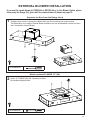
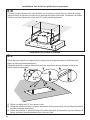
1
2
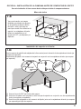
Unfasten the 4 screws to dismount the Blower Box from the hood body and to save screws.
The Blower Box is not used for Remote Blower installation and can be discarded or saved for future
use if converted to Internal Blower.
Attach 10" FLANGE (2A) with 4 screws provided in
the hardware bag as shown.
lfyouusetheremoteblowerkit,RB900kitorRB1200kitorIn-LineBlowerOption,please
throwawaytheange(3A)givenwiththeremoteblowerkit,shownonpage10.
EXTERNAL BLOWER INSTALLATION
Separate the Box from the Range Hood
Attach optional FLANGE 10" (2A)
Torx Screwdriver
Torx Screwdriver

18
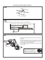
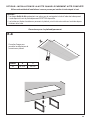
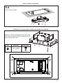
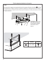
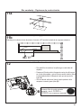
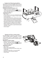
3
Connect the Hood body air outlet with the
Remote Blower air outlet.
4
Connect to Air Outlet
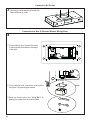
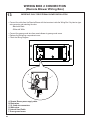
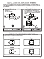
Connection to Box 2 (Remote Blower Wiring Box)
1. From inside the hood connect the cable
to the wiring box 2 as shown in the image
to the right.
2. From inside the hood, remove the cover from the
wiring box 2 by removing two screws.
3. Break the correct hole in the Wiring Box 2 for
passing the cables from the remote blower.
2
2
Box
1
2

19
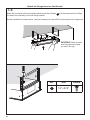
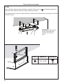
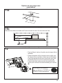
Fixing the Security Cable
Fix the Free part of Security Cable at the panel with a Screw 7 supplied.
A
B
C

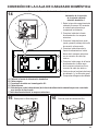
20
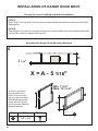
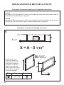
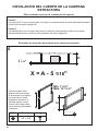
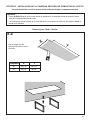
INSTALLATION OF RANGE HOOD BODY
X = A - 5 1/16"
$
PP
; $PP
;
%[
5 1/16"
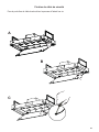
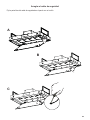
6
As shown, you have to
accommodate for the
height of the hood body
into your space overhead.
After determining bracket
height use the 8 Screws
from Component Page 8 to
assemble brackets.
$
PP
; $PP
;
%[
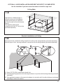
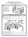
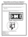
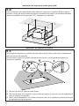
5
Min. 7 5/16"
Max. 12 13/16"
Option A
Steps 7a-7b-7c is an option for mounting and hood when access is available from above the ceiling/soft
(See page 20).
Option B
Steps 8a-8b-8c is an option for mounting the hood to the brackets when no access is available from above
and the soft is already completed (See page 22).
Choose the correct method of bracket installation
Assemble the Range Hood Mounting Brackets
Ref. Size Picture
G
1/8" x 3/8"
G
La page est en cours de chargement...
La page est en cours de chargement...
La page est en cours de chargement...
La page est en cours de chargement...
La page est en cours de chargement...
La page est en cours de chargement...
La page est en cours de chargement...
La page est en cours de chargement...
La page est en cours de chargement...
La page est en cours de chargement...
La page est en cours de chargement...
La page est en cours de chargement...
La page est en cours de chargement...
La page est en cours de chargement...
La page est en cours de chargement...
La page est en cours de chargement...
La page est en cours de chargement...
La page est en cours de chargement...
La page est en cours de chargement...
La page est en cours de chargement...
La page est en cours de chargement...
La page est en cours de chargement...
La page est en cours de chargement...
La page est en cours de chargement...
La page est en cours de chargement...
La page est en cours de chargement...
La page est en cours de chargement...
La page est en cours de chargement...
La page est en cours de chargement...
La page est en cours de chargement...
La page est en cours de chargement...
La page est en cours de chargement...
La page est en cours de chargement...
La page est en cours de chargement...
La page est en cours de chargement...
La page est en cours de chargement...
La page est en cours de chargement...
La page est en cours de chargement...
La page est en cours de chargement...
La page est en cours de chargement...
La page est en cours de chargement...
La page est en cours de chargement...
La page est en cours de chargement...
La page est en cours de chargement...
La page est en cours de chargement...
La page est en cours de chargement...
La page est en cours de chargement...
La page est en cours de chargement...
La page est en cours de chargement...
La page est en cours de chargement...
La page est en cours de chargement...
La page est en cours de chargement...
La page est en cours de chargement...
La page est en cours de chargement...
La page est en cours de chargement...
La page est en cours de chargement...
La page est en cours de chargement...
La page est en cours de chargement...
La page est en cours de chargement...
La page est en cours de chargement...
La page est en cours de chargement...
La page est en cours de chargement...
La page est en cours de chargement...
La page est en cours de chargement...
La page est en cours de chargement...
La page est en cours de chargement...
La page est en cours de chargement...
La page est en cours de chargement...
La page est en cours de chargement...
La page est en cours de chargement...
La page est en cours de chargement...
La page est en cours de chargement...
La page est en cours de chargement...
La page est en cours de chargement...
La page est en cours de chargement...
La page est en cours de chargement...
La page est en cours de chargement...
La page est en cours de chargement...
La page est en cours de chargement...
La page est en cours de chargement...
-
 1
1
-
 2
2
-
 3
3
-
 4
4
-
 5
5
-
 6
6
-
 7
7
-
 8
8
-
 9
9
-
 10
10
-
 11
11
-
 12
12
-
 13
13
-
 14
14
-
 15
15
-
 16
16
-
 17
17
-
 18
18
-
 19
19
-
 20
20
-
 21
21
-
 22
22
-
 23
23
-
 24
24
-
 25
25
-
 26
26
-
 27
27
-
 28
28
-
 29
29
-
 30
30
-
 31
31
-
 32
32
-
 33
33
-
 34
34
-
 35
35
-
 36
36
-
 37
37
-
 38
38
-
 39
39
-
 40
40
-
 41
41
-
 42
42
-
 43
43
-
 44
44
-
 45
45
-
 46
46
-
 47
47
-
 48
48
-
 49
49
-
 50
50
-
 51
51
-
 52
52
-
 53
53
-
 54
54
-
 55
55
-
 56
56
-
 57
57
-
 58
58
-
 59
59
-
 60
60
-
 61
61
-
 62
62
-
 63
63
-
 64
64
-
 65
65
-
 66
66
-
 67
67
-
 68
68
-
 69
69
-
 70
70
-
 71
71
-
 72
72
-
 73
73
-
 74
74
-
 75
75
-
 76
76
-
 77
77
-
 78
78
-
 79
79
-
 80
80
-
 81
81
-
 82
82
-
 83
83
-
 84
84
-
 85
85
-
 86
86
-
 87
87
-
 88
88
-
 89
89
-
 90
90
-
 91
91
-
 92
92
-
 93
93
-
 94
94
-
 95
95
-
 96
96
-
 97
97
-
 98
98
-
 99
99
-
 100
100


Faber Stratus 36 SS Guide d'installation
- Catégorie
- Hottes
- Taper
- Guide d'installation
- Ce manuel convient également à
dans d''autres langues
Documents connexes
-
Faber High-Light 36 SSNB Le manuel du propriétaire
-
-
Faber Stratus 48 SS Guide d'installation
-
-
-
-
-
-
-