KitchenAid KERS507XSS01 Guide d'installation
- Catégorie
- Fours
- Taper
- Guide d'installation

INSTALLATIONINSTRUCTIONS
FREESTANDINGELECTRICRANGEWITHDOUBLEOVENS
INSTRUCTIONSD'INSTALLATIONPOURCUISINIERE
ELECTRIQUEAUTOPORTANTEAVEC FOURSDOUBLES
Table of Contents Table des mati_res
RANGE SAFETY ......................................................................... 1
INSTALLATION REQUIREMENTS ............................................ 2
Tools and Parts........................................................................ 2
Location Requirements ............................................................ 2
Electrical Requirements - U.S.A. Only ..................................... 4
Electrical Requirements - Canada Only .................................. 5
INSTALLATION INSTRUCTIONS .............................................. 6
Unpack Range ......................................................................... 6
Adjust Leveling Legs ................................................................ 6
Install Anti-Tip Bracket ............................................................. 7
Electrical Connection - U.S.A. Only......................................... 8
Verify Anti-Tip Bracket Location ............................................ 13
Level Range ........................................................................... 13
Complete Installation ............................................................. 13
Moving the Range .................................................................. 14
SI_CURITI_ DE LA CUISINIERE .............................................. 16
EXIGENCES D'INSTALLATION .............................................. 17
Outils et pieces ..................................................................... 17
Exigences d'emplacement ................................................... 17
Specifications electriques - Canada seulement .................. 19
INSTRUCTIONS D'INSTALLATION ....................................... 20
Deballage de la cuisiniere ..................................................... 20
Reglage des pieds de nivellement ........................................ 20
Installation de la bride antibasculement ............................... 21
Verification de I'emplacement de la
bride antibasculement .......................................................... 22
Reglage de I'aplomb de la cuisiniere .................................... 22
Achever I'installation ............................................................. 22
Deplacement de la cuisiniere ................................................ 23
RANGESAFETY
Your safety and the safety of others are very important.
We have provided many important safety messages in this manual and on your appliance. Always read and obey all safety
messages.
This is the safety alert symbol.
This symbol alerts you to potential hazards that can kill or hurt you and others.
All safety messages will follow the safety alert symbol and either the word "DANGER" or "WARNING."
These words mean:
You can be killed or seriously injured if you don't immediately
follow instructions.
You can be killed or seriously injured if you don't follow
instructions.
All safety messages will tell you what the potential hazard is, tell you how to reduce the chance of injury, and tell you what can
happen if the instructions are not followed.
IMPORTANT:
Save for local electrical inspector's use.
IMPORTANT :
,&,conserver pour consultation par I'inspecteur local des installations 61ectriques.
W10289536A

Tip Over Hazard
A child or adult can tip the range and be killed.
Connect anti-tip bracket to rear range foot.
Reconnect the anti-tip bracket, if the range is moved.
Failure to follow these instructions can result in death or serious burns to children and adults.
INSTALLATIONREQUIREMENTS
s :xnd
Gather the required tools and parts before starting installation.
Read and follow the instructions provided with any tools listed
here.
Tools needed
• Tape measure • Wrench or pliers
• Level • 3/8"nut driver
• Phillips screwdriver • Hand or electric drill
• Flat-blade screwdriver • 1/8"(3.2 mm) drill bit
Parts supplied
Check that all parts are included.
3 - 10-32 hex nuts (attached to terminal block)
3 - Terminal lugs
Oven racks
2 - #12 x 1%" screws (for mounting anti-tip bracket)
Anti-tip bracket (taped inside upper oven with package
containing literature)
Anti-tip bracket must be securely mounted to back wall or
floor. Thickness of floor may require longer screws to anchor
bracket to subfloor. Longer screws are available from your
local hardware store.
Parts needed
If using a power supply cord:
• A UL listed power supply cord kit marked for use with ranges.
The cord should be rated at 250 volts minimum, 40 amps or
50 amps that is marked for use with nominal 13/8"(3.5 cm)
diameter connection opening and must end in ring terminals
or open-end spade terminals with upturned ends.
• A UL listed strain relief.
Check local codes. Check existing electrical supply. See
"Electrical Requirements" section.
It is recommended that all electrical connections be made by a
licensed, qualified electrical installer.
IMPORTANT: Observe allgoverningcodes and ordinances.
• ItistheinstaIIer'sresponsibilitytocomply withinstallation
clearancesspecifiedon the model/serialratingplate.The
modeIlserialratingplateislocatedbehindthecontrolpanel.
The rangeshouldbe locatedforconvenientuse inthe
kitchen.
To eliminate the risk of burns or fire by reaching over heated
surface units, cabinet storage space located above the
surface units should be avoided. If cabinet storage is to be
provided, the risk can be reduced by installing a range hood
that projects horizontally a minimum of 5" (12.7 cm) beyond
the bottom of the cabinets.
Cabinet opening dimensions that are shown must be used.
Given dimensions are minimum clearances.
The floor anti-tip bracket must be installed. To install the anti-
tip bracket shipped with the range, see "Install Anti-Tip
Bracket" section.
• Grounded electrical supply is required. See "Electrical
Requirements" section.
IMPORTANT: To avoid damage to your cabinets, check with your
builder or cabinet supplier to make sure that the materials used
will not discolor, delaminate or sustain other damage. This range
has been designed in accordance with the requirements of UL
and CSA International and complies with the maximum allowable
wood cabinet temperatures of 194°F (90°C).
Mobile Home - Additional Installation Requirements
The installation of this range must conform to the Manufactured
Home Construction and Safety Standard, Title 24 CFR, Part 3280
(formerly the Federal Standard for Mobile Home Construction
and Safety, Title 24, HUD Part 280). When such standard is not
applicable, the Standard for Manufactured Home Installations,
ANSI A225.1/NFPA 501A or with local codes.
Mobile home installations require:
• When this range is installed in a mobile home, it must be
secured to the floor during transit. Any method of securing
the range is adequate as long as it conforms to the standards
listed above.
• Four-wire power supply cord or cable must be used in a
mobile home installation. The appliance wiring will need to be
revised. See "Electrical Connection" section.
2

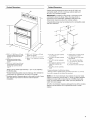
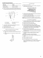
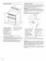
Product Dimensions
A _
Cabinet Dimensions
Cabinet opening dimensions shown are for 25" (63.5 cm)
countertop depth, 24" (61.0 cm) base cabinet depth and
36" (91.4 cm) countertop height.
IMPORTANT: If installing a range hood or microwave hood
combination above the range, follow the range hood or
microwave hood combination installation instructions for
dimensional clearances above the cooktop surface.
A freestanding range may be installed next to combustible walls
with zero clearance.
F
D
A. 353/4'' _+%" (90.8 cm +_0.3 cm)
cooktop height (minimum) with
leveling legs screwed all the
way in*
B. Model/serial/ra ring plates
(located behind the control
panel)**
C. 47% " +1/s" (119. T cm +_O.3 cm)
overafl height (minimum) with
leveling legs screwed all the
way in*
D. 281/2''_+1/4"(72.4 cm +_0.6 cm)
depth with handle
E. 26%" + %" (66.4 cm +_0.3 cm)***
F. 2915/16'' + 1A6"(76.0 cm +_0.2 cm)
width
*Range can be raised approximately 1" (2.5 cm) by adjusting
the leveling legs.
**Model/serial/rating plates may be rotated up from behind the
control panel for viewing from the front of the range.
***Excludes handle. Dimension given is from wall to front of oven
door and will vary based on electric outlet receptacle
installation.
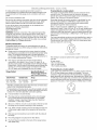
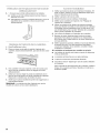
A. 18" (45.7 cm) upper cabinet
to countertop
B. 13" (33.0 cm) upper cabinet
depth
C. 30" (76.2 cm) min. opening
width.
D. For minimum clearance to the
top of the cooktop, see
NOTE.
E. 30" (76.2 cm) min. opening
width
E Cabinet door or hinge should
not extend into cutout*
G. lY2" (3.8 cm) min. from right
side cabinet
H. 2" (5.1 cm) min. from floor
I. 7" (17.8 cm) min. from floor
J. 8" (20.3 cm) width
K. 3Y2"(8.91 cm) min. from floor
Proper positioning of outlet shown above.
*Nothing located in shaded areas can extend more than lY2" (3.8 cm)
from wall or range will not slide all the way back.
NOTE: 24" (61.0 cm) minimum when bottom of wood or metal
cabinet is covered by not less than 1/4"(0.64 cm) flame retardant
millboard covered with not less than No. 28 MSG sheet steel,
0.015" (0.4 mm) stainless steel, 0.024" (0.6 mm) aluminum or
0.020" (0.5 mm) copper.
30" (76.2 cm) minimum clearance between the top of the cooking
platform and the bottom of an unprotected wood or metal
cabinet.

Ifcodespermitandaseparategroundwireisused,itis
recommendedthataqualifiedelectricalinstallerdeterminethat
thegroundpathandwiregaugeareinaccordancewithlocal
codes.
Donotuseanextensioncord.
Besurethattheelectricalconnectionandwiresizeareadequate
andinconformancewiththeNationalElectricalCode,ANSI/
NFPA70-latesteditionandalllocalcodesandordinances.
Acopyoftheabovecodestandardscanbeobtainedfrom:
NationalFireProtectionAssociation
OneBatterymarchPark
Quincy,MA02269.
WARNING:Improperconnectionoftheequipment-grounding
conductorcanresultinariskofelectricshock.Checkwitha
qualifiedelectricianorservicetechnicianifyouareindoubtasto
whethertheapplianceisproperlygrounded.Donotmodifythe
powersupplycordplug.Ifitwillnotfittheoutlet,haveaproper
outletinstalledbyaqualifiedelectrician.
Electrical Connection
To properly install your range, you must determine the type of
electrical connection you will be using and follow the instructions
provided for it here.
• Range must be connected to the proper electrical voltage
and frequency as specified on the model/serial number rating
plate. The model/serial/rating plate is located behind the
control panel. Refer to the figures in "Product Dimensions" in
the "Location Requirements" section.
• This range is manufactured with the neutral terminal
connected to the cabinet. Use a 3-wire, UL listed, 40- or
50-amp power supply cord (pigtail) (see the following Range
Rating chart). If local codes do not permit ground through the
neutral, use a 4-wire power supply cord rated at 250 volts,
40 or 50 amps and investigated for use with ranges.
Range Rating* Specified Rating of
Power Supply Cord Kit
and Circuit Protection
120/240 Volts 120/208 Volts Amps
8.8- 16.5 KW 7.8 - 12.5 KW 40 or 50"*
16.6 - 22.5 KW 12.6 - 18.5 KW 50
*The NEC calculated load is less than the total connected load
listed on the model/serial/rating plate.
**If connecting to a 50-amp circuit, use a 50-amp rated cord with
kit. For 50-amp rated cord kits, use kits that specify use with a
nominal 13/8"(34.9 mm) diameter connection opening.
• A circuit breaker is recommended.
If connecting to a 4-wire system:
This range ismanufactured with the ground connected to the
neutral by a link. The ground must be revised so the green
ground wire of the 4-wire power supply cord is connected to the
cabinet. See "Electrical Connection Section."
Grounding through the neutral conductor is prohibited for new
branch-circuit installations (1996 NEC); mobile homes; and
recreational vehicles, or an area where local codes prohibit
grounding through the neutral conductor.
When a 4-wire receptacle of NEMA Type 14-50R is used, a
matching UL listed, 4-wire, 250-volt, 40- or 50-amp, range power
supply cord (pigtail) must be used. This cord contains 4 copper
conductors with ring terminals or open-end spade terminals with
upturned ends, terminating in a NEMA Type 14-50P plug on the
supply end.
The fourth (grounding) conductor must be identified by a green or
green/yellow cover and the neutral conductor by a white cover.
Cord should be Type SRD or SRDT with a UL listed strain relief
and be at least 4 ft (1.22 m) long.
4-wire receptacle (14-50R)
The minimum conductor sized for the copper 4-wire power
cord are:
40-amp circuit
2 No.-8 conductors
1 No.-10 white neutral
1 No.-8 green grounding
If connecting to a 3-wire system:
Local codes may permit the use of a UL listed, 3-wire, 250-volt,
40- or 50-amp range power supply cord (pigtail). This cord
contains 3 copper conductors with ring terminals or open-end
spade terminals with upturned ends, terminating in a NEMA Type
10-50P plug on the supply end. Connectors on the appliance end
must be provided at the point the power supply cord enters the
appliance. This uses a 3-wire receptacle of NEMA Type 10-50R.
O
3-wire receptacle (10-50R)
• The range can be connected directly to the circuit breaker
box (or fused disconnect) through flexible or nonmetallic
sheathed, copper or aluminum cable. See the "Electrical
Connection - U.S.A Only." section.
• Allow 2 to 3 ft (61.0 cm to 91.4 cm) of slack in the line so that
the range can be moved if servicing is ever necessary.
• A UL listed conduit connector must be provided at each end
of the power supply cable (at the range and at the junction
box).
• Wire sizes and connections must conform with the rating of
the range.
• The wiring diagram is located on the Tech Sheet.
• The Tech Sheet is located on the back of the range inside a
clear plastic bag.

Electrical Shock Hazard
Electrically ground range.
Failure to do so can result in death, fire, or
electrical shock.
If codes permit and a separate ground wire is used, it is
recommended that a qualified electrical installer determine that
the ground path is adequate and wire gauge are in accordance
with local codes.
Be sure that the electrical connection and wire size are adequate
and in conformance with CSA Standard C22.1, Canadian
Electrical Code, Part 1 - latest edition, and all local codes and
ordinances.
A copy of the above code standards can be obtained from:
Canadian Standards Association
178 Rexdale Blvd.
Toronto, ON M9W 1R3 CANADA
• Check with a qualified electrical installer if you are not sure
the range is properly grounded.
Range Rating* Specified Rating of
Power Supply Cord Kit
and Circuit Protection
120/240 Volts 120/208 Volts Amps
8.8- 16.5 KW 7.8 - 12.5 KW 40 or 50"*
16.6 - 22.5 KW 12.6 - 18.5 KW 50
*The NEC calculated load is less than the total connected load
listed on the model/serial rating plate.
**If connecting to a 50-amp circuit, use a 50-amp rated cord with
kit. For 50-amp rated cord kits, use kits that specify use with a
nominal 13/8"(34.9 mm) diameter connection opening.
A time-delay fuse or circuit breaker is recommended.
This range is equipped with a CSA International Certified
Power Cord intended to be plugged into a standard 14-50R
wall receptacle. Be sure the wall receptacle is within reach of
range's final location.
• Do not use an extension cord.

INSTALLATIONINSTRUCTIONS
Excessive Weight Hazard
Use two or more people to move and install range.
Failure to do so can result in back or other injury.
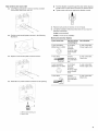
1. Remove shipping materials, tape and film from the range.
Keep cardboard bottom under range.
2. Remove oven racks and parts package from inside oven.
3. To place range on its back, take 4 cardboard corners from the
carton. Stack one cardboard corner on top of another.
Repeat with the other 2 corners. Place them lengthwise on
the floor behind the range to support the range when it is laid
on its back.
4. Using 2 or more people, firmly grasp the range and gently lay
it on its back on the cardboard corners.
5. Pull cardboard bottom firmly to remove.
6. Use an adjustable wrench to loosen the leveling legs.
7. Place cardboard or hardboard in front of range. Using 2 or
more people, stand range back up onto cardboard or
hardboard.
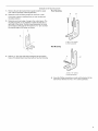
1.
us£Le e/i
If range height adjustment is necessary, use a wrench or
pliers to loosen the 4 leveling legs.
This may be done with the range on its back or with the range
supported on 2 legs after the range has been placed back to
a standing position.
NOTE: To place range back up into a standing position, put a
sheet of cardboard or hardboard in front of range. Using 2 or
more people, stand range back up onto the cardboard or
hardboard.
Tip Over Hazard
A child or adult can tip the range and be killed.
Connect anti-tip bracket to rear range foot.
Reconnect the anti-tip bracket, if the range is moved.
Failure to follow these instructions can result in death
or serious burns to children and adults.
2. Adjust the leveling legs to the correct height. Leveling legs
can be loosened to add up to a maximum of 1" (2.5 cm). A
minimum of 3Ae"(5.0 mm) is needed to engage the anti-tip
bracket.
NOTE: If height adjustment is made when range is standing,
tilt the range back to adjust the front legs, then tilt forward to
adjust the rear legs.
3. When the range is at the correct height, check that there is
adequate clearance under the range for the anti-tip bracket.
Before sliding range into its final location, check that the anti-
tip bracket will slide under the range and onto the rear
leveling leg prior to anti-tip bracket installation.
6

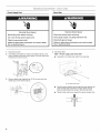
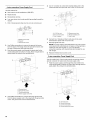
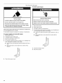
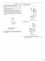
1. Remove the anti-tip bracket that is taped inside the upper Floor Mounting
oven with the package containing literature.
2. Determine which mounting method to use: floor or wall.
If you have a stone or masonry floor you can use the wall
mounting method.
3. Determine and mark edge of range in the cutout space. The
mounting bracket can be installed on either the left side or
right side of the cutout. Position mounting bracket in cutout
so that right (or left) edge of the bracket is _%e"(2.4 cm) from
the marked edge of the range, as shown.
4=
A
B
Drill two %" (3.0 mm) holes that correspond to the bracket
holes of the determined mounting method. See the following.
Wall Mounting
A B
A. #12 x 1%" screws
B.Anti-tip bracket
5=
A. #12 x 1%" screws
B. Anti-tip bracket
Using the Phillips screwdriver, mount anti-tip bracket to the
wall or floor with the two #12 x 15/8'' screws provided.

Power Supply Cord
Electrical Shock Hazard
Disconnect power before servicing.
Use a new 40 amp power supply cord.
Plug into a grounded outlet.
Failure to follow these instructions can result in death,
fire, or electrical shock.
Direct Wire
Electrical Shock Hazard
Disconnect power before servicing.
Use 8 gauge copper or 6 gauge aluminum wire.
Electrically ground range.
Failure to follow these instructions can result in death,
fire, or electrical shock.
1=
2.
3.
Disconnect power.
Use Phillips screwdriver to remove the terminal block cover
screw located on the back of the range. Pull cover down and
toward you to remove cover.
Remove plastic tag holding three 10-32 hex nuts from the
middle post of the terminal block.
4= Add strain relief.
Style 1: Power supply cord strain relief
• Assemble a UL listed strain relief in the opening.
A
A. UL listed strain relief
Feed the power supply cord through the strain relief in the
cord/conduit plate on bottom of range. Allow enough
slack to easily attach the wiring to the terminal block.
• Tighten strain relief screw against the power supply cord.
8

Style 2: Direct wire strain relief
• Use Phillips screwdriver to remove screws and slide
cord/conduit plate down and out.
f ...............
Position cord/conduit plate as shown in the following
illustration.
• Replace cord/conduit plate and insert screws.
• Assemble a UL listed conduit connector in the opening.
• Feed the flexible conduit through the strain relief, allowing
enough slack to easily attach wiring to the terminal block.
• Tighten strain relief screw against the flexible conduit.
5. Replace back panel and screws on rear of range.
6. Complete installation following instructions for your type of
electrical connection:
4-wire (recommended)
3-wire (if 4-wire is not available)
Electrical Connection Options
If your home has: And you will be Go to Section:
connecting to:
4-wire receptacle A UL listed,
(NEMA type 14-50R) 250-volt
minimum,
40-amp, range
power supply
cord
4-wire connection:
Power supply cord
4-wire direct A fused
disconnect or
circuit breaker
(12.7 cm) box
4-wire connection:
Direct wire
3-wire receptacle A UL listed,
(NEMA type 10-50R) 250-volt
minimum,
40-amp, range
power supply
cord
3-wire connection:
Power supply cord
3-wire direct A fused 3-wire connection:
1- disconnect or Direct wire
circuit breaker
box
/-i7-.gom)_
A. Removable retaining nut
B. Strain relief

4-wire connection: Power Supply Cord
Use this method for:
• New branch-circuit installations (1996 NEC)
• Mobile homes
• Recreational vehicles
• In an area where local codes prohibit grounding through the
neutral
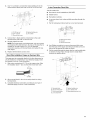
1. Part of metal ground strap must be cut out and removed.
5. Use 3/8"nut driver to connect the neutral (white) wire to the
center terminal block post with one of the 10-32 hex nuts.
B
C
",,
A. Metal ground strap
B. Discard
C. Ground-link screw
A
B
C
2. Use Phillips screwdriver to remove the ground-link screw
from the back of the range. Save the ground-link screw and
the end of the ground link under the screw.
3. Feed the power supply cord through the strain relief in the
cord/conduit plate on bottom of range. Allow enough slack to
easily attach the wiring to the terminal block.
A ....... q
I................ "i::Li_ :_i
.... /
i _.:_ : ::_:[ .....
D
A. 10-32 hex nut
B. Ground-link screw
C. Line 1 (black)
D. Green ground wire
E. Neutral (center) wire
F. Line 2 (red)
6. Connect line 1 (black) and line 2 (red) wires to the outer
terminal block posts with 10-32 hex nuts.
7. Securely tighten hex nuts.
NOTE: For power supply cord replacement, only use a power
cord rated at 250 volts minimum, 40 amps or 50 amps that is
marked for use with nominal 13/8"(3.5 cm) diameter
connection opening, with ring terminals and marked for use
with ranges.
8. Replace terminal block access cover.
3-wire connection: Power Supply Cord
Use this method only if local codes permit connecting chassis
ground conductor to neutral wire of power supply cord.
1. Feed the power supply cord through the strain relief in the
cord/conduit plate on bottom of range. Allow enough slack to
easily attach the wiring to the terminal block.
4................:: iiiii
B
4.
A. Terminal block
B. Ground-link screw
C. Cord/conduit plate
D. Power supply cord wires
Use Phillips screwdriver to connect the green ground wire
from the power supply cord to the range with the ground-link
screw. The ground wire must be attached first.
C
A. Terminal block
B. Ground-link screw
C. Cord/conduit plate
D. Power supply cord wires
D
10

2. Use 3/8"nut driver to connect the neutral (white) wire to the
center terminal block post with one of the 10-32 hex nuts.
A
B
C
E
A. 10-32 hex nut
B. Line 1 (black)
C. Ground-link screw
D. Neutral (white) wire
E.Line 2 (red)
3. Connect line 1 (black) and line 2 (red) wires to the outer
terminal block posts with 10-32 hex nuts.
4. Securely tighten hex nuts.
NOTE: For power supply cord replacement, only use a power
cord rated at 250 volts minimum, 40 amps or 50 amps that is
marked for use with nominal 13/8"(3.5 cm) diameter
connection opening, with ring terminals and marked for use
with ranges.
5. Replace terminal block access cover.
Direct Wire Installation: Copper or Aluminum Wire
This range may be connected directly to the fuse disconnect or
circuit breaker box. Depending on your electrical supply, make
the required 3-wire or 4-wire connection.
1. Strip outer covering back 3" (7.6 cm) to expose wires. Strip
the insulation back 1" (2.5 cm) from the end of each wire.
1Jt
4-wire Connection: Direct Wire
Use this method for:
• New branch-circuit installations (1996 NEC)
• Mobile homes
• Recreational vehicles
• In an area where local codes prohibit grounding through the
neutral
1. Part of metal ground strap must be cut out and removed.
2=
3=
,,,,,
_,,,,,, 'L.........
A.Metal ground strap
B.Discard
C.Ground-link screw
A
B
C
Use Phillips screwdriver to remove the ground-link screw
from the back of the range. Save the ground-link screw and
the end of the ground link under the screw.
Pull the conduit through the strain relief on cord/conduit plate
on bottom of range. Allow enough slack to easily attach
wiring to the terminal block.
i i ............... B
i
I //
(7.6 crn)
2. Allow enough slack in the wire to easily attach the wiring
terminal block.
3. Complete electrical connection according to your type of
electrical supply (4-wire or 3-wire connection).
G
F
D
A. Terminal block
B. Ground-link screw
C. Cord/conduit plate
D. Line 2 (red) wire
E. Neutral (white) wire
F. Line 1 (black) wire
G. Bare (green) ground wire
11

4=
Attach terminal lugs to line 1 (black), neutral (white), and line 2
(red) wires. Loosen (do not remove) the setscrew on the front
of the terminal lug and insert exposed wire end through
bottom of terminal lugs. Securely tighten setscrew to
XX Ibs-in. torque. See Bare Wire Torque Specifications chart.
C
E
A. Terminal lug
B. Setscrew
C. Line 1 (black) wire
D. Neutral (white) wire
E.Line 2 (red) wire
Bare Wire Torque Specifications
Attaching terminal lugs to the terminal block - 20 Ibs-in. (2.3 N-m)
Wire Awg Torque
8 gauge copper 25 Ibs-in. (2.8 N-m)
6 gauge aluminum 35 Ibs-in. (4.0 N-m)
5. Use Phillips screwdriver to connect the bare (green) ground
wire to the range with the ground-link screw. The ground wire
must be attached first and must not contact any other
terminal.
6. Use 3/8"nut driver to connect the neutral (white) wire to the
center terminal block post with one of the 10-32 hex nuts.
3-wire connection: Direct Wire
Use this method only if local codes permit connecting ground
conductor to neutral supply wire.
1. Pull the conduit through the hole and conduit plate on bottom
of range. Allow enough slack to easily attach the wiring to the
terminal block.
//
C
2=
F
A. Terminal block
B. Ground-link screw
C. Cord/conduit plate
D. Line 2 (red) wire
E. Bare (green) ground wire
F. Line 1 (black) wire
Attach terminal lugs to line 1 (black), bare (green) ground, and
line 2 (red) wires. Loosen (do not remove) the setscrew on the
front of the terminal lug and insert exposed wire end through
bottom of terminal lugs. Securely tighten setscrew to
XX Ibs-in. torque. See Bare Wire Torque Specifications chart.
A
A
S _
E
G
F
C
A. 10-32 hex nut
B. Line 1 (black)
C. Bare (green) ground wire
D. Ground-link screw
E. Neutral (white) wire
F. Line 2 (red)
G. Terminal lug
7. Connect line 1 (black) and line 2 (red) wires to the outer
terminal block posts with 10-32 hex nuts.
8. Securely tighten hex nuts.
9. Replace terminal block access cover.
C
D
A. Terminal lug
B. Setscrew
C. Line 1 (black) wire
D. Bare (green) ground wire
E.Line 2 (red) wire
12

Bare Wire Torque Specifications
Attaching terminal lugs to the terminal block - 20 Ibs-in. (2.3 N-m)
Wire Awg Torque
8 gauge copper 25 Ibs-in. (2.8 N-m)
6 gauge aluminum 35 Ibs-in. (4.0 N-m)
3. Use 3/8"nut driver to connect the bare (green) ground wire to
the center terminal block post with one of the 10-32 hex nuts.
A
B
F
E
D
C
A. 10-32 hex nut
B. Line 1 (black)
C. Ground-link screw
D. Bare (green) ground wire
E.Line 2 (red)
F. Terminal lug
4. Connect line 1 (black) and line 2 (red) wires to the outer
terminal block posts with 10-32 hex nuts.
5. Securely tighten hex nuts.
6. Replace terminal block access cover.
1.
_l_ ¸ _ _o_
Make sure the anti-tip bracket is installed:
• Look for the anti-tip bracket securely attached to floor or
wall.
• Slide range back so rear range foot is under the anti-tip
bracket.
1
1.
2.
L @
Place oven rack in oven.
Place level on oven rack and check levelness of range, first
side to side; then front to back.
3. If range is not level, pull range forward until rear leveling leg is
removed from the anti-tip bracket.
4. Use wrench to adjust leveling legs up or down until range is
level. Push range back into position.
5. Check that rear leveling leg is engaged in anti-tip bracket.
NOTE: Range must be level for satisfactory baking performance.
1. Check that all parts are now installed. If there is an extra part,
go back through the steps to see which step was skipped.
2. Check that you have all of your tools.
3. Dispose of/recycle all packaging materials.
4. Check that the range is level. See "Level Range."
5. Use a mild solution of liquid household cleaner and warm
water to remove waxy residue caused by shipping material.
Dry thoroughly with a soft cloth. For more information, read
the "Range Care" section of the Use and Care Guide.
6. Read the range Use and Care Guide.
7. Plug power cord into appropriate outlet. Slide range into its
final location. Check that the flexible conduit or power supply
cord are not bent.
8. Turn power on. Turn on surface elements and oven. See the
Use and Care Guide for specific instruction on range
operation.
If range does not operate, check the following:
• Household fuse is intact and tight; or circuit breaker has not
tripped.
• Range is plugged into an outlet.
• Electrical supply is connected.
• See "Troubleshooting" in the Use and Care Guide.
When the range has been on for 5 minutes, check for heat. If
range is cold, turn off the range and contact a qualified
technician.
13

For direct-wired ranges:
Tip Over Hazard
A child or adult can tip the range and be killed.
Connect anti=tip bracket to rear range foot.
Reconnect the anti=tip bracket, if the range is moved.
Failure to follow these instructions can result in death
or serious burns to children and adults.
When moving range, slide range onto cardboard or hardboard to
avoid damaging the floor covering.
If removing the range is necessary for cleaning or maintenance:
For power supply cord-connected ranges:
1. Slide range forward.
2. Unplug the power supply cord.
3. Complete cleaning or maintenance.
4. Plug in power supply cord.
5. To check that anti-tip bracket is installed, use a flashlight and
look underneath the bottom of the range:
• Look for the anti-tip bracket securely attached to floor or
wall.
• Slide range back so rear range foot is under anti-tip
bracket.
Electrical Shock Hazard
Disconnect power before servicing.
Replace all parts and panels before operating.
Failure to do so can result in death or electrical shock.
1=
2.
3.
4.
Disconnect power.
Slide range forward.
Complete cleaning or maintenance.
To check that anti-tip bracket is installed, use a flashlight and
look underneath the bottom of the range:
• Look for the anti-tip bracket securely attached to floor or
wall.
• Slide range back so rear range foot is under anti-tip
bracket.
5. Check that range is level.
6. Reconnect power.
6. Check that range is level.
14

15

SECURITEDELACUISINIERE
Votre securite et celle des autres est tres importante.
Nous donnons de nombreux messages de s_curit_ importants dans ce manuel et sur votre appareil m_nager. Assurez-vous de
toujours lire tous les messages de s_curit_ et de vous y conformer.
Voici le symbole d'alerte de s_curit&
Ce symbole d'alerte de s_curit_ vous signale les dangers potentiels de d_c_s et de blessures graves & vous
et & d'autres.
Tousles messages de s_curit_ suivront le symbole d'alerte de s_curit_ et le mot "DANGER" ou
"AVERTISSEMENT". Ces mots signifient •
Risque possible de d_cbs ou de blessure grave si vous ne
suivez pas imm_diatement les instructions.
Risque possible de d_cbs ou de blessure grave si vous
ne suivez pas les instructions.
Tousles messages de s_curit_ vous diront quel est le danger potentiel et vous disent comment r_duire le risque de blessure et
ce qui peut se produire en cas de non-respect des instructions.
Risque de basculement
Un enfant ou une personne adulte peut faire basculer la cuisiniere ce qui peut causer un d_ces.
Joindre la bride antibasculement au pied arriere de la cuisiniere.
Joindre de nouveau la bride antibasculement si la cuisiniere est d_plac_e.
Le non-respect de ces instructions peut causer un d_ces ou des brQlures graves aux enfants et
aux adultes.
16

EXIGENCESD'INSTALLATION
p®ces
Rassembler les outils et pieces necessaires avant d'entreprendre
I'installation. Lire et suivre les instructions fournies avec chacun
des outils de la liste ci-dessous.
Outils n_cessaires
• Metre-ruban • Cle ou pince
• Niveau • Tourne-ecrou 3/8"
• Tournevis Phillips • Perceuse manuelle ou
• Tournevis & lame plate electrique
• Foret de 1/8"(3,2 mm)
Pi_ces fournies
Verifier que toutes les pieces sont presentes.
• 3 ecrous hexagonaux de 10-32 (joints au bloc de
raccordement)
3 attaches de bornes
Grilles du four
2 vis #12 x 18/8"(pour le montage de la bride antibasculement)
Bride anti-basculement (fixee par ruban adhesif a I'interieur
du four superieur avec le sachet de documentation
La bride antibasculement doit _tre bien fixee & la cloison
arriere ou au plancher. La profondeur du plancher peut
necessiter des vis plus Iongues pour I'ancrage de la bride
dans le sous-plancher. Des vis plus Iongues sont disponibles
aupres de votre quincaillerie locale.
Pi_ces n_cessaires
En cas d'utilisation d'un cordon d'alimentation _lectrique :
• Cordon d'alimentation (homologation UL) con£su pour
I'utilisation avec une cuisiniere. Pour service 250 volts
minimum, 40 A ou 50 A, compatible avec une ouverture de
diametre nominal 13/8'' (3,5 cm) pour le raccordement, et avec
cosses rondes ou en fourche a pointes relevees a I'extremite
de chaque conducteur.
• Un serre-c&ble (homologation UL).
Consulter les codes Iocaux. Verifier I'alimentation electrique
existante. Voir la section "Specifications electriques".
II est recommande de faire realiser tous les raccordements
electriques par un electricien qualifie agree.
IMPORTANT : Observer les dispositions de tousles codes et
reglements en vigueur.
• C'est a I'installateur qu'incombe la responsabilite de
respecter les distances de separation exigees, specifiees sur
la plaque signaletique de I'appareil. La plaque signaletique se
trouve derriere le tableau de commande.
La cuisiniere doit _tre installee a un endroit pratique dans la
cuisine.
Afin de supprimer le risque de brQlures ou d'incendie lie au
fait de se pencher au-dessus des plaques de cuisson
chaudes, les placards de rangement au-dessus des plaques
doivent _tre evites. Si des placards de rangement sont
envisages, le risque peut _tre reduit par I'installation d'une
hotte de cuisine depassant le bas des placards d'au moins 5"
(12,7 cm) horizontalement.
Respecter les dimensions indiquees pour les ouvertures
decouper dans les placards. Ces dimensions constituent les
valeurs minimales des degagements.
La bride antibasculement de plancher doit _tre installee. Pour
I'installation de la bride antibasculement fournie avec la
cuisiniere, voir la section "Installation de la bride
antibasculement".
• Une source d'electricite avec liaison & la terre est necessaire.
Voir la section "Specifications electriques".
IMPORTANT :Afin d'eviter d'endommager les placards,
consulter le constructeur de la maison ou le fabricant des
placards pour determiner si les materiaux utilises peuvent subir
un changement de couleur, une destratification ou d'autres
dommages. Cette cuisiniere a ete con£sue conformement aux
exigences des normes UL et CSA International et respecte les
temperatures maximales permises de 194°F (90°C) pour les
placards en bois.
R_sidence mobile - Specifications additionnelles
respecter Iors de I'installation
L'installation de cette cuisiniere doit _tre conforme aux
dispositions de la norme Manufactured Home Construction and
Safety Standard, Title 24 CFR, Part 3280 (anciennement Federal
Standard for Mobile Home Construction and Safety, Title 24,
HUD Part 280). Lorsque cette norme n'est pas applicable,
I'installation doit satisfaire aux criteres de la norme Standard for
Manufactured Home Installations, ANSI A225.1/NFPA 501A ou
aux dispositions des codes Iocaux.
Autres crit_res a respecter pour une installation en r_sidence
mobile :
• Dans le cas de I'installation de cette cuisiniere dans une
residence mobile, la cuisiniere doit _tre fixee au plancher
durant tout deplacement du vehicule. Toute methode de
fixation de la cuisiniere est adequate dans la mesure oQelle
satisfait aux criteres des normes mentionnees ci-dessus.
Pour une installation en residence mobile, un c&ble ou cordon
d'alimentation & quatre fils doit _tre utilis& Le c&blage de
I'appareil devra _tre revise. Voir la section "Raccordement
electrique".
17

Dimensions du product
A*
Dimensions du placard
Les dimensions de I'espace d'installation entre les placards sont
valides pour I'installation entre des placards de 24" (61 cm) avec
plan de travail de 25" (63,5 cm) a hauteur de 36" (91,4 cm).
Hauteur du plan de travail 36" (91,4 cm)
IMPORTANT • En cas d'installation d'une hotte ou d'un
ensemble hotte/micro-ondes au-dessus de la cuisiniere, suivre
les instructions fournies avec la hotte concernant les dimensions
de degagement & respecter au-dessus de la surface de la table
de cuisson.
Une cuisiniere autoportante peut etre installee sans aucun
degagement & proximite de parois combustibles.
F
A. Hauteur jusqu '_ la partie
inf_rieure de la table de culsson
avec les pieds de nivellement
completement abaiss_s :
353/4'' + %" (90,8 cm +_0,3 cm)*
B. Plaques signal#tiques (situ_es
derriere le tableau de
commande)**
C. Hauteur hors-tout (minimum)
avec les pieds de nivellement
completement abaiss_s :
47%" _+%" (119,7cm +_0,3 cm)*
D.Profondeur avec la poign_e de
281/2"_+1/4"(72,4 cm +_0,6 cm)
E.26%" +_%" (66,4 cm +_0,3 cm)***
F. Largeur de 2915/16'' +_1A6"
(76 cm +_0,2 cm)
*La cuisiniere peut etre surelevee d'environ 1" (2,5 cm) en
ajustant les pieds de nivellement.
**11est possible de faire pivoter les plaques signaletiques vers le
haut & partir de I'arriere du tableau de commande afin qu'elles
soient visibles depuis I'avant de la cuisiniere.
***Poignee non comprise. La dimension fournie correspond & la
distance du mur & I'avant de la porte du four et varie en
fonction de I'installation de la prise electrique murale.
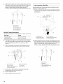
1
t
j;J
K
A. 18" (45,7cm) entre leplacard F. Laporte ou charniere du
sup_rieur et le plan de travail placard ne doit pas d_passer
B.Profondeur des placards I'int_rieur de I'ouverture*
sup_rieurs : 13" (33,0cm) G. lY2"(3,8cm)min. depuis le
C.Largeur de I'ouverture 30" placard de droite
(76,2 cm) min. H. 2" (5,1cm) min. depuis le
D.Pour ladistance fibre plancher
minimale versla partie I. 7"(17,8 cm)min. depuis le
sup_rieure de la tablede plancher
cuisson, voir laREMARQUE. J. 8" (20,3 cm)de largeur
E.Largeur de I'ouverture 30" K.3Y2"(8,91cm)min. depuis le
(76,2 cm) min. plancher
Position correcte de la prise illustr_e ci-dessus.
*Aucun _l_ment situ_ dans les zones gris_es ne doit d_passer de plus
de 1Y2"(3,8 cm) depuis lemur ou la cuisiniere ne glissera pas jusqu 'au
fond.
REMARQUE • Distance de separation minimale de 24" (61 cm)
Iorsque le fond d'un placard de bois ou de metal est protege par
une planche ignifugee d'au moins 1/4"(0,64 cm) recouverte d'une
feuille metallique d'epaisseur egale ou superieure & : acier calibre
28 MSG, acier inoxydable 0,015" (0,4 mm), aluminium 0,024"
(0,6 mm), ou cuivre 0,020" (0,5 mm).
Distance de separation de 30" (76,2 cm) ou plus entre le dessus
de la table de cuisson et le fond d'un placard de bois ou de metal
non protege.
18

Electrical Shock Hazard
Electrically ground range.
Failure to do so can result in death, fire, or
electrical shock.
Si I'on utilise un conducteur distinct de liaison & la terre Iorsque
les codes le permettent, il est recommande qu'un electricien
qualifie verifie que la liaison & la terre est adequate et la section
des ills conforme aux codes Iocaux.
Verifier que le raccordement & la source d'electricit6 et le calibre
des conducteurs sont conformes aux prescriptions de la plus
recente edition de la norme CSA C22.1, partie 1-Code canadien
de 1'61ectricite, et de tout code ou r_glement local en vigueur.
Pour obtenir un exemplaire des normes des codes ci-dessus,
contacter :
Canadian Standards Association
178 Rexdale Blvd.
Toronto, ON M9W 1R3 CANADA.
• En cas de doute quant &la qualite de la liaison & la terre de la
cuisiniere, consulter un electricien qualifi&
Puissance nominale de la Intensit_ nominale
cuisini_re* sp_cifi_e du cordon
d'alimentation et de la
protection du circuit
120/240 volts 120/208 volts A
8,8 &16,5 kW 7,8 & 12,5 kW 40 ou 50**
16,6 & 22,5 kW 12,6 & 18,5 kW 50
*La charge NEC calculee est inferieure & la charge totale
connectee indiqu6e sur la plaque signaletique.
**En cas de raccordement & un circuit de 50 A, utiliser un cordon
de 50 A nominaux avec son necessaire. Pour les cordons de
50 A nominaux, utiliser des necessaires qui specifient une
utilisation avec une ouverture pour le raccordement d'un
diam_tre nominal de 13/8"(34,9 mm).
• On recommande d'utiliser un fusible ou un disjoncteur
temporis&
• Cette cuisiniere est equipee d'un cordon electrique
homologue par la CSA International &brancher dans une
prise murale standard 14-50R. Veiller & ce que la prise murale
se trouve &proximite de I'emplacement definitif de la
cuisiniere.
• Ne pas utiliser de c&ble de rallonge.
19

INSTRUCTIONSD'INSTALLATION
Risque du poids e×cessff
Utiliser cleux ou plus de personnes pour d_placer et
installer la cuisini_re.
Le non-respect de cette instruction peut causer
une blessure au dos ou d'autre blessure.
1. Oter les materiaux d'emballage, le ruban adhesif et le film de
la cuisiniere. Laisser la base de carton sous la cuisiniere.
2. Retirer les grilles de four et le sachet de pieces de I'interieur
du four.
3. Pour placer la cuisiniere sur sa partie posterieure, sortir les
4 coins de protection du carton d'emballage. Empiler I'un des
coins sur un autre. Repeter avec les 2 autres coins. Les
disposer sur le plancher dans le sens de la Iongueur derriere
la cuisiniere en guise de support Iorsque la cuisiniere est
placee sur sa partie posterieure.
4. A I'aide de deux personnes ou plus, saisir fermement la
cuisiniere et la poser delicatement sur sa partie posterieure,
sur les coins de protection.
5. Tirer fermement sur la partie inferieure du carton pour le
retirer.
6. Utiliser une cle a molette pour desserrer les pieds de
nivellement.
7. Placer le carton ou le panneau de fibres dur devant la
cuisiniere. A I'aide de deux personnes ou plus, relever la
cuisiniere et la placer sur le carton ou sur le panneau de fibres
dur.
1.
6@c gedes pi@s de n bme@
8i un ajustement de la hauteur de la cuisiniere est necessaire,
utiliser une cle ou une pince pour desserrer les 4 pieds de
nivellement.
Ceci dolt _tre effectue alors que la cuisiniere repose sur sa
partie posterieure ou qu'elle est soutenue par 2 pieds apres
avoir ete replacee en position verticale.
RFMARQUF : Pour replacer la cuisiniere en position
verticale, placer un carton ou un panneau de fibres dur
devant la cuisiniere. A I'aide de deux personnes ou plus,
relever la cuisiniere et la placer sur le carton ou le panneau de
fibres dur.
Risque de basculement
Un enfant ou une personne adulte peut faire basculer
la cuisini_re ce qui peut causer un d_c_s.
Joindre la bride antibasculement au pied arri_re de
la cuisini_re.
Joindre de nouveau la bride antibasculement si la
cuisini_re est d_plac_e.
Le non-respect de ces instructions peut causer un
d_c_s ou des brQlures graves aux enfants et aux
adultes.
2. Ajuster les pieds de nivellement a la hauteur necessaire. Les
pieds de nivellement peuvent _tre desserres pour ajouter une
hauteur maximale de 1" (2,5 cm). Un minimum de 3A6"
(5,0 mm) est necessaire pour engager la bride
antibasculement.
REMARQUE • Si un ajustement de la hauteur est effectue
alors que la cuisiniere est debout, incliner la partie arriere de
la cuisiniere pour ajuster les pieds avant, puis incliner la
cuisiniere vers I'avant pour ajuster les pieds arriere.
3. Lorsque la cuisiniere est a la hauteur souhaitee, verifier qu'il y
a un espace suffisant sous la cuisiniere pour Ioger la bride
antibasculement. Avant de faire glisser la cuisiniere a son
emplacement final, verifier qu'il sera possible de faire glisser
la bride antibasculement sous la cuisiniere et sur le pied de
nivellement arriere avant I'installation de la bride
antibasculement.
20
La page est en cours de chargement...
La page est en cours de chargement...
La page est en cours de chargement...
La page est en cours de chargement...
-
 1
1
-
 2
2
-
 3
3
-
 4
4
-
 5
5
-
 6
6
-
 7
7
-
 8
8
-
 9
9
-
 10
10
-
 11
11
-
 12
12
-
 13
13
-
 14
14
-
 15
15
-
 16
16
-
 17
17
-
 18
18
-
 19
19
-
 20
20
-
 21
21
-
 22
22
-
 23
23
-
 24
24


KitchenAid KERS507XSS01 Guide d'installation
- Catégorie
- Fours
- Taper
- Guide d'installation
dans d''autres langues
Documents connexes
Autres documents
-
Jenn-Air JES8850CAS00 Guide d'installation
-
IKEA GY399LXUQ04 Guide d'installation
-
Maytag MET8885XB Installation Instructions Manual
-
-
-
-
-
-
-
IKEA IES505DS0 Guide d'installation