
• Sales and Service through Subsidiaries and Distributors Worldwide •
Cleveland, Ohio 44117-1199 U.S.A. TEL: 216.481.8100 FAX: 216.486.1751 WEB SITE: www.lincolnelectric.com
• World's Leader in Welding and Cutting Products •
OPERATOR’S MANUAL
Copyright © Lincoln Global Inc.
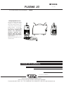
PLASMA 20
IM10006
June, 2009
Safety Depends on You
Lincoln arc welding and cutting
equipment is designed and built
with safety in mind. However, your
overall safety can be increased by
proper installation ... and thought-
ful operation on your part. DO
NOT INSTALL, OPERATE OR
REPAIR THIS EQUIPMENT
WITHOUT READING THIS
MANUAL AND THE SAFETY
PRECAUTIONS CONTAINED
THROUGHOUT. And, most
importantly, think before you act
and be careful.
For use with machines having Code Number:
11578

PROTECT YOURSELF AND OTHERS FROM POSSIBLE SERIOUS INJURY OR DEATH. KEEP CHILDREN
AWAY. PACEMAKER WEARERS SHOULD CONSULT WITH THEIR DOCTOR BEFORE OPERATING.
Read and understand the following safety highlights. For additional safety information it is strongly recommended that you
purchase a copy of “Safety in Welding & Cutting - ANSI Standard Z49.1” from the American Welding Society, P.O. Box
351040, Miami, Florida 33135 or CSA Standard W117.2.
BE SURE THAT ALL INSTALLATION, OPERATION, MAINTENANCE, AND REPAIR PROCEDURES ARE
PERFORMED ONLY BY QUALIFIED INDIVIDUALS.
CUTTING SPARKS can
cause fire or explosion.
4.a. Remove fire hazards from the plasma cut-
ting or gouging area. If this is not possible, cover
them to prevent the cutting or gouging sparks
from starting a fire. Remember that welding
sparks and hot materials from plasma cutting or gouging can
easily go through small cracks and openings to adjacent
areas. Avoid cutting or gouging near hydraulic lines. Have a
fire extinguisher readily available.
4.b. Where compressed gases are to be used at the job site, spe-
cial precautions should be used to prevent hazardous situa-
tions. Refer to “Safety in Welding and Cutting” (ANSI
Standard Z49.1) and the operating information for the equip-
ment being used.
ARC RAYS can burn.
2.a. Use safety glasses and a shield with the prop-
er filter and cover plates to protect your eyes from
sparks and the rays of the arc when performing or
observing plasma arc cutting or gouging.
Glasses,headshield and filter lens should conform
to ANSI Z87. I standards.
2.b. Use suitable clothing including gloves made from durable
flame-resistant material to protect your skin and that of your
helpers from the arc rays.
2.c. Protect other nearby personnel with suitable non-flammable
screening and/or warn them not to watch the arc nor expose
themselves to the arc rays or to hot spatter or metal.
ELECTRIC SHOCK can
kill.
1.a. The electrode and work (or ground) circuits
are electrically “hot” when the power source is on.
Do not touch these “hot” parts with your bare skin
or wet clothing. Wear dry, hole-free gloves to
insulate hands.
1.b. When the power source is operating voltages in excess of
250 volts are produced. This creates the potential for serious
electrical shock - potentially even fatal.
1.c. Insulate yourself from work and ground using dry insulation.
When cutting or gouging in damp locations, on metal frame-
work such as floors, gratings or scaffolds and when in posi-
tions such as sitting or lying, make certain the insulation is
large enough to cover your full area of physical contact with
work and ground.
1.d. Always be sure the work cable makes a good electrical con-
nection with the metal being cut or gouged. The connection
should be as close as possible to the area being cut or
gouged.
1.e. Ground the work or metal to be cut or gouged to a good elec-
trical (earth) ground.
1.f. Maintain the plasma torch, cable and work clamp in good,
safe operating condition. Replace damaged insulation.
1.g. Never dip the torch in water for cooling or plasma cut or
gouge in or under water.
1.h. When working above floor level, protect yourself from a fall
should you get a shock.
1.i. Operate the pilot arc with caution. The pilot arc is capable of
burning the operator, others or even piercing safety clothing.
1.j. Also see Items 4c and 6.
WARNING
PLASMA CUTTING or GOUGING can be hazardous.
FUMES AND GASES
can be dangerous.
3.a. Plasma cutting or gouging may produce
fumes and gases hazardous to health. Avoid
breathing these fumes and gases. When cutting
or gouging, keep your head out of the fumes.
Use enough ventilation and/or exhaust at the arc
to keep fumes and gases away from the breathing zone.
When plasma cutting or gouging on lead or cadmium
plated steel and other metals or coatings which produce
highly toxic fumes keep exposure as low as possible
and below Threshold Limit Values (TLV) using local
exhaust or mechanical ventilation. In confined spaces or
in some circumstances, outdoors, a respirator may be
required. Additional precautions are also required when
plasma cutting or gouging on galvanized steel.
3. b. The operation of plasma cutting or gouging fume control
equipment is affected by various factors including proper
use and positioning of the equipment, maintenance of the
equipment and the specific procedure and application
involved. Worker exposure level should be checked upon
installation and periodically thereafter to be certain it is with-
in applicable OSHA PEL and ACGIH TLV limits.
3.c. Do not use plasma cutting or gouging equipment in locations
near chlorinated hydrocarbon vapors coming from degreas-
ing, cleaning or spraying operations. The heat and rays of
the arc can react with solvent vapors to form phosgene, a
highly toxic gas, and other irritating products.
3.d. Gases used for plasma cutting and gouging can displace air
and cause injury or death. Always use enough ventilation,
especially in confined areas, to insure breathing air is safe.
3.e. Read and understand the manufacturer’s instructions for this
equipment and follow your employer’s safety practices.
Aug. ‘06
i
SAFETY
i

4.c. When not cutting or gouging, make certain no part of the elec-
trode circuit is touching the work or ground. Accidental contact
can cause overheating and create a fire hazard.
4.d. Do not cut or gouge tanks, drums or containers until the proper
steps have been taken to insure that such procedures will not
cause flammable or toxic vapors from substances inside. They
can cause an explosion even though they have been
“cleaned.” For information purchase “Recommended Safe
Practices for the Preparation for Welding and Cutting of
Containers and Piping That Have Held Hazardous
Substances”, AWS F4.1 from the American Welding Society
(see address above).
4.e. Vent hollow castings or containers before heating, cutting or
gouging. They may explode.
4.f. Do nor fuel engine driven equipment near area where plasma
cutting or gouging.
4.g. Sparks and spatter are thrown from the plasma arc. Wear
safety glasses, ear protection and oil free protective garments
such as leather gloves, heavy shirt, cuffless trousers, high
shoes and a cap over your hair. Wear ear plugs when cutting
or gouging out of position or in confined places. Always wear
safety glasses with side shields when in a cutting or gouging
area.
4.h. Connect the work cable to the work as close to the cutting or
gouging area as practical. Work cables connected to the build-
ing framework or other locations away from the cutting or
gouging area increase the possibility of the current passing
through lifting chains, crane cables or other alternate circuits.
This can create fire hazards or overheat lifting chains or
cables until they fail.
4.I. Read and follow NFPA 51B “ Standard for Prevention During
Welding, Cutting and Other Hot Work”, available from NFPA, 1
Batterymarch Park,PO box 9101, Quincy, Ma 022690-9101.
FOR ELECTRICALLY
powered equipment.
6.a. Turn off input power using the disconnect
switch at the fuse box before working on the
equipment.
6.b. Install equipment in accordance with the U.S. National
Electrical Code, all local codes and the manufacturer’s rec-
ommendations.
6.c. Ground the equipment in accordance with the U.S. National
Electrical Code and the manufacturer’s recommendations.
CYLINDER may explode
if damaged.
5.a. Use only compressed gas cylinders contain-
ing the correct gas for the process used and
properly operating regulators designed for the
gas and pressure used. All hoses, fittings, etc.
should be suitable for the application and maintained in good
condition.
5.b. Always keep cylinders in an upright position securely
chained to an undercarriage or fixed support.
5.c. Cylinders should be located:
• Away from areas where they may be struck or subjected to
physical damage.
• A safe distance from plasma cutting or gouging, arc weld-
ing operations and any other source of heat, sparks,
or flame.
5.d. Never allow any part of the electrode, torch or any other
electrically “hot” parts to touch a cylinder.
5.e. Keep your head and face away from the cylinder valve outlet
when opening the cylinder valve.
5.f. Valve protection caps should always be in place and hand
tight except when the cylinder is in use or connected for
use.
5.g. Read and follow the instructions on compressed gas cylin-
ders, associated equipment, and CGA publication P-l,
“Precautions for Safe Handling of Compressed Gases in
Cylinders,”available from the Compressed Gas Association
1235 Jefferson Davis Highway, Arlington, VA 22202.
Jan., 07
ELECTRIC AND MAGNETIC
FIELDS
may be dangerous
8.a. Electric current flowing through any con-
ductor causes localized Electric and Magnetic
Fields (EMF). Cutting or gouging current cre-
ates EMF fields around torch cables and cutting
machines.
8.b. EMF fields may interfere with some pacemakers, so opera-
tors having a pacemaker should consult their physician
before cutting or gouging.
8.c. Exposure to EMF fields during cutting or gouging may have
other health effects which are now not known.
8d. All operators should use the following procedures in order to
minimize exposure to EMF fields from the cutting or gouging
circuit:
8.d.1. Route thetorch andwork cablestogether - Secure
them with tape when possible.
8.d.2. Never coil the torch cable around your body.
8.d.3. Do not place your body between the torch and
work cables. Ifthe torch cableison yourrightside,
the work cable should also be on your right side.
8.d.4. Connect the work cable to the workpiece as close as
possible to the area being cut or gouged.
8.d.5. Do not work next to cutting power source.
PLASMA ARC can injure.
7.a. Keep your body away from nozzle and
plasma arc.
7.b. Operate the pilot arc with caution. The pilot arc is capable of
burning the operator, others or even piercing safety clothing.
ii
SAFETY
ii

NOTES

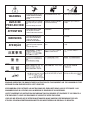
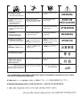
PRÉCAUTIONS DE SÛRETÉ
Pour votre propre protection lire et observer toutes les instructions
et les précautions de sûreté specifiques qui parraissent dans ce
manuel aussi bien que les précautions de sûreté générales suiv-
antes:
Sûreté Pour Soudage A L’Arc
1. Protegez-vous contre la secousse électrique:
a. Les circuits à l’électrode et à la piéce sont sous tension
quand la machine à souder est en marche. Eviter toujours
tout contact entre les parties sous tension et la peau nue
ou les vétements mouillés. Porter des gants secs et sans
trous pour isoler les mains.
b. Faire trés attention de bien s’isoler de la masse quand on
soude dans des endroits humides, ou sur un plancher
metallique ou des grilles metalliques, principalement dans
les positions assis ou couché pour lesquelles une grande
partie du corps peut être en contact avec la masse.
c. Maintenir le porte-électrode, la pince de masse, le câble
de soudage et la machine à souder en bon et sûr état
defonctionnement.
d.Ne jamais plonger le porte-électrode dans l’eau pour le
refroidir.
e. Ne jamais toucher simultanément les parties sous tension
des porte-électrodes connectés à deux machines à souder
parce que la tension entre les deux pinces peut être le
total de la tension à vide des deux machines.
f. Si on utilise la machine à souder comme une source de
courant pour soudage semi-automatique, ces precautions
pour le porte-électrode s’applicuent aussi au pistolet de
soudage.
2. Dans le cas de travail au dessus du niveau du sol, se protéger
contre les chutes dans le cas ou on recoit un choc. Ne jamais
enrouler le câble-électrode autour de n’importe quelle partie
du corps.
3. Un coup d’arc peut être plus sévère qu’un coup de soliel,
donc:
a. Utiliser un bon masque avec un verre filtrant approprié
ainsi qu’un verre blanc afin de se protéger les yeux du ray-
onnement de l’arc et des projections quand on soude ou
quand on regarde l’arc.
b. Porter des vêtements convenables afin de protéger la
peau de soudeur et des aides contre le rayonnement de
l‘arc.
c. Protéger l’autre personnel travaillant à proximité au
soudage à l’aide d’écrans appropriés et non-inflammables.
4. Des gouttes de laitier en fusion sont émises de l’arc de
soudage. Se protéger avec des vêtements de protection libres
de l’huile, tels que les gants en cuir, chemise épaisse, pan-
talons sans revers, et chaussures montantes.
5. Toujours porter des lunettes de sécurité dans la zone de
soudage. Utiliser des lunettes avec écrans lateraux dans les
zones où l’on pique le laitier.
6. Eloigner les matériaux inflammables ou les recouvrir afin de
prévenir tout risque d’incendie dû aux étincelles.
7. Quand on ne soude pas, poser la pince à une endroit isolé de
la masse. Un court-circuit accidental peut provoquer un
échauffement et un risque d’incendie.
8. S’assurer que la masse est connectée le plus prés possible
de la zone de travail qu’il est pratique de le faire. Si on place
la masse sur la charpente de la construction ou d’autres
endroits éloignés de la zone de travail, on augmente le risque
de voir passer le courant de soudage par les chaines de lev-
age, câbles de grue, ou autres circuits. Cela peut provoquer
des risques d’incendie ou d’echauffement des chaines et des
câbles jusqu’à ce qu’ils se rompent.
9. Assurer une ventilation suffisante dans la zone de soudage.
Ceci est particuliérement important pour le soudage de tôles
galvanisées plombées, ou cadmiées ou tout autre métal qui
produit des fumeés toxiques.
10. Ne pas souder en présence de vapeurs de chlore provenant
d’opérations de dégraissage, nettoyage ou pistolage. La
chaleur ou les rayons de l’arc peuvent réagir avec les vapeurs
du solvant pour produire du phosgéne (gas fortement toxique)
ou autres produits irritants.
11. Pour obtenir de plus amples renseignements sur la sûreté,
voir le code “Code for safety in welding and cutting” CSA
Standard W 117.2-1974.
PRÉCAUTIONS DE SÛRETÉ POUR
LES MACHINES À SOUDER À
TRANSFORMATEUR ET À
REDRESSEUR
1. Relier à la terre le chassis du poste conformement au code de
l’électricité et aux recommendations du fabricant. Le dispositif
de montage ou la piece à souder doit être branché à une
bonne mise à la terre.
2. Autant que possible, I’installation et l’entretien du poste seront
effectués par un électricien qualifié.
3. Avant de faires des travaux à l’interieur de poste, la debranch-
er à l’interrupteur à la boite de fusibles.
4. Garder tous les couvercles et dispositifs de sûreté à leur
place.
Mar. ‘93
iv
SAFETY
iv

vv
TThhaannkk YYoouu
for selecting a QUALITY product by Lincoln Electric. We want you
to take pride in operating this Lincoln Electric Company product
••• as much pride as we have in bringing this product to you!
Read this Operators Manual completely before attempting to use this equipment. Save this manual and keep it
handy for quick reference. Pay particular attention to the safety instructions we have provided for your protection.
The level of seriousness to be applied to each is explained below:
WARNING
This statement appears where the information must be followed exactly to avoid serious personal injury or loss of life.
This statement appears where the information must be followed to avoid minor personal injury or damage to this equipment.
CAUTION
Please Examine Carton and Equipment For Damage Immediately
When this equipment is shipped, title passes to the purchaser upon receipt by the carrier. Consequently, Claims
for material damaged in shipment must be made by the purchaser against the transportation company at the
time the shipment is received.
Please record your equipment identification information below for future reference. This information can be
found on your machine nameplate.
Product _________________________________________________________________________________
Model Number ___________________________________________________________________________
Code Number or Date Code_________________________________________________________________
Serial Number____________________________________________________________________________
Date Purchased___________________________________________________________________________
Where Purchased_________________________________________________________________________
Whenever you request replacement parts or information on this equipment, always supply the information you
have recorded above. The code number is especially important when identifying the correct replacement parts.
On-Line Product Registration
- Register your machine with Lincoln Electric either via fax or over the Internet.
• For faxing: Complete the form on the back of the warranty statement included in the literature packet
accompanying this machine and fax the form per the instructions printed on it.
• For On-Line Registration: Go to our
WEB SITE at www.lincolnelectric.com. Choose “Quick Links” and then
“Product Registration”. Please complete the form and submit your registration.
CUSTOMER ASSISTANCE POLICY
The business of The Lincoln Electric Company is manufacturing and selling high quality welding equipment, consumables, and cutting equip-
ment. Our challenge is to meet the needs of our customers and to exceed their expectations. On occasion, purchasers may ask Lincoln
Electric for advice or information about their use of our products. We respond to our customers based on the best information in our posses-
sion at that time. Lincoln Electric is not in a position to warrant or guarantee such advice, and assumes no liability, with respect to such infor-
mation or advice. We expressly disclaim any warranty of any kind, including any warranty of fitness for any customer’s particular purpose,
with respect to such information or advice. As a matter of practical consideration, we also cannot assume any responsibility for updating or
correcting any such information or advice once it has been given, nor does the provision of information or advice create, expand or alter any
warranty with respect to the sale of our products.
Lincoln Electric is a responsive manufacturer, but the selection and use of specific products sold by Lincoln Electric is solely within the control
of, and remains the sole responsibility of the customer. Many variables beyond the control of Lincoln Electric affect the results obtained in
applying these types of fabrication methods and service requirements.
Subject to Change – This information is accurate to the best of our knowledge at the time of printing. Please refer to www.lincolnelectric.com
for any updated information.

vivi
TABLE OF CONTENTS
Page
Installation.......................................................................................................................Section A
Technical Specifications.......................................................................................................A-1
Safety Precautions ...............................................................................................................A-2
Select Proper Location.........................................................................................................A-2
Stacking................................................................................................................................A-2
Tilting....................................................................................................................................A-2
High Frequency Interference Protection...............................................................................A-2
Input Electrical Connections.................................................................................................A-2
Compressed Air or Gas Input Connections..........................................................................A-3
Connections to Ground Cable..............................................................................................A-3
Torch Connections ...............................................................................................................A-3
________________________________________________________________________________
Operation.........................................................................................................................Section B
Safety Precautions ...............................................................................................................B-1
Description ...........................................................................................................................B-1
User Responsibility...............................................................................................................B-2
Design Features and Advantages........................................................................................B-2
Cutting Capability .................................................................................................................B-2
Torch Consumables ............................................................................................................B-2
Limitations ............................................................................................................................B-2
Controls and Settings...........................................................................................................B-2
Cutting Operations ...............................................................................................................B-3
Check Air Quality..................................................................................................................B-3
Cutting with a Hand Torch ............................................................................................B-3, B-4
Pilot Arc Discussion..............................................................................................................B-5
Torch Consumable Parts Selection......................................................................................B-5
________________________________________________________________________
Maintenance ....................................................................................................Section D
Safety Precautions ................................................................................................D-1
Routine Maintenance.............................................................................................D-1
Periodic Maintenance............................................................................................D-1
Compressed Air Filter............................................................................................D-2
________________________________________________________________________
Troubleshooting..............................................................................................Section E
Safety Precautions.................................................................................................E-1
How to Use Troubleshooting Guide.......................................................................E-1
Troubleshooting Guide ..........................................................................................E-2
________________________________________________________________________
Wiring Diagrams..............................................................................................Section F
Wiring Diagram......................................................................................................F-1
––––––––––––––––––––––––––––––––––––––––––––––––––––––––––––––––––––––––
Parts Lists....................................................................................................P-607Series
________________________________________________________________________

A-1
INSTALLATION
PLASMA 20
A-1
Weight
Including
Torch Cable
21 lbs.
9.5 kg.
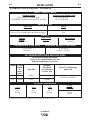
INPUT - SINGLE PHASE
RATED OUTPUT
OUTPUT
RECOMMEND INPUT WIRE AND FUSE SIZES
REQUIRED AIR FLOW RATE REQUIRED AIR INLET PRESSURE
PHYSICAL DIMENSIONS
TECHNICAL SPECIFICATIONS - PLASMA 20
Standard Voltage
Duty Cycle
50% on 115V (15 Amp Branch)
40% on 115V (20 Amp Branch with 20 Amp Plug*)
Current
Range
10-20 Amps
AC Input
Voltage
at
50/60
Hertz
115V-1Ø
115V-1Ø
Maximum
Time-Delay
Circuit Breaker
or Fuse Size
20 AMPS
15 Amps
3 Conductor, #14 AWG
Type SJT or Hard Usage
Input Cord
Depth
16 in.
406 mm
Width
6 in.
152 mm
Height
12 in.
305 mm
Open Circuit
Voltage
310 VDC
For all plasma cutting applications
Based on U.S. National Electrical Code
Ambient Temperature 30
o
C or Less
Pilot Current
17 Amps
AMPS
15 A
20 A
1Ø Input Current at Rated Output
115/1/50/60Hz (15 Amp Branch)
115/1/50/60Hz (20 Amp Branch with 20 Amp Plug*)
115 V: 20A @ 50%
115 V: 26A @ 40%
3.5 cu. ft./min.
(100L/min.)
72.5 to 150 PSI
( 5 Bar TO 10.3 Bar)
20 A
15 A
Output
Plug Size
5-20P*
5-15P
*5-20P plug must comply with the standard for attachment plugs and receptacles, UL498.

A-2
INSTALLATION
PLASMA 20
A-2
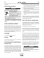
Read entire Installation Section before installing the
PLASMA 20.
SAFETY PRECAUTIONS
ELECTRIC SHOCK CAN KILL.
• Only qualified personnel should
perform this installation.
• Only personnel that have read and
understood the PLASMA 20
Operating Manual should install
and operate this equipment.
• Machine must be plugged into a receptacle
which is grounded per any national, local or
other applicable electrical codes.
• The PLASMA 20 power switch is to be in the OFF
(“O”) position when installing work cable and
gun and when connecting power cord to input
power.
___________________________________________
SELECT PROPER LOCATION
Place the PLASMA 20 where clean cool air can freely
circulate in and out the front, rear and side louvers.
Dirt, dust, smoke, gas or any foreign material that can
be drawn into the machine should be kept at a mini-
mum. Insure open space of at least 15 ft. around the
machine. Failure to observe these precautions can
result in excessive operating temperatures and nui-
sance shutdown of the machine.
STACKING
The PLASMA 20 cannot be stacked.
TILTING
The PLASMA 20 must be placed on a stable, level
surface so it will not topple over.
HIGH FREQUENCY INTERFERENCE
PROTECTION
The PLASMA 20 employs a touch start mechanism for
arc initiation which eliminates high frequency emis-
sions from the machine as compared with spark gap
and solid state type high frequency generators. Keep
in mind, though, that these machines may be used in
an environment where other high frequency generat-
ing machines are operating. By taking the following
steps, high frequency interference into the PLASMA
20 can be minimized.
(1) Make sure the power supply chassis is connected
to a good earth ground. The work terminal ground
does NOT ground the machine frame.
(2) Keep the work clamp isolated from other work
clamps that have high frequency.
(3) If the work clamp cannot be isolated, then keep
the clamp as far as possible from other work
clamp connections.
(4) When the machine is enclosed in a metal building,
several good earth driven electrical grounds
around the periphery of the building are recom-
mended.
Failure to observe these recommended installation
procedures may cause improper function of the PLAS-
MA 20 or possibly even damage to the control system
or power supply components.
INPUT ELECTRICAL CONNECTIONS
The PLASMA 20 must be connected to a Line-Neutral
system with protective grounding wire. Check that the
relevant electrical outlet is actually connected to the
distribution system grounding.
The PLASMA 20 is rated for 115VAC input.
Use on 15 amp branch circuits will limit cutting output.
When the output is set at 16 amps or greater, the
input fuse or circuit breaker may “blow” in roughly 30
seconds or less (depending on fuse or circuit breaker
type).
To achieve 16-20 amp output with 115VAC input,
replace the 15 amp plug on the input cord with a 20
amp plug, and connect the unit to a 20 amp branch
circuit with super lag fuses (or equivalent breaker). To
install 20 amp plug: Connect the white (neutral) wire
under terminal clamp with silver screw, and black (hot)
wire under terminal clamp with brass screw. Connect
green wire under terminal clamp with green screw.
Tighten terminal wire clamp screws securely.
5-20P plug must comply with the standard for attach-
ment plugs and receptacles, UL498. This product is
acceptable for use only when an attachment plug as
specified is properly attached to the supply cord.
• Failure to wire as instructed may cause personal
injury or damage to equipment.
• To be installed or checked by an electrician or
qualified person only.
------------------------------------------------------------------------
WARNING
WARNING

A-3
INSTALLATION
PLASMA 20
A-3
Use of normal 20 amp household breakers may result
in over current trips. If breaker trips occur, reduce the
cutting current output until nuisance trips stop.
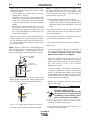
COMPRESSED AIR OR GAS INPUT
CONNECTION
A source of clean, dry air or nitrogen must be supplied
to the PLASMA 20. Oil in the air is a severe problem
and must be avoided. The supply pressure must be
between 72.5 and 150 psi (5 and 10.3 bar). The flow
rate is approximately 3.5 cu. ft./min. (100L/min.).
Failure to observe these precautions could result in
excessive operating temperatures or damage to the
torch.
Air with considerable quantity of humidity or oil
may cause an excessive wear of the parts or even
damage the torch.
If there are any doubts about the quality of the
compressed air available, it is suggested that an
air dryer be installed before the input filter
. Using
flexible airline, connect the compressed air to the
rear of the machine. Do not exceed maximum
entry pressure of 150 PSI (10.3 Bar). The pressure
must be adjusted to 72.5 PSI (5 Bar), minimum.
-----------------------------------------------------------------
•
To use the air fitting supplied with the machine apply
teflon tape to the fitting threads and install the fitting in
the port at the rear of the machine.
NOTE: When using nitrogen gas from a cylinder, the
cylinder must have a pressure regulator.
• Maximum psi from a nitrogen gas cylinder to
the PLASMA 20 regulator should never
exceed 150 psi (10.3 Bar).
• Install a hose between the nitrogen gas cylin-
der regulator and the PLASMA 20 gas inlet.
CYLINDER could explode if damaged.
• Keep cylinder upright and
chained to a fixed support.
• Keep cylinder away from areas
where it could be damaged.
• Never lift machine with cylinder attached.
• Never allow the cutting torch to touch the cylin-
der.
• Keep cylinder away from live electrical parts.
• Maximum inlet pressure 150 PSI (10.3 Bar).
__________________________________________
CONNECTION TO GROUND CABLE
Connect the work cable clamp to the piece to be cut
or to the metallic workbench. Take the following pre-
cautions:
Verify that there is a good electrical contact particular-
ly if insulated or oxidated coated sheets are cut.
Make ground connections as close as possible to the
cutting area. The use of the metallic structures which
are not part of the workpiece, such as return cable of
the cutting current, may endanger the safety system
and give poor cutting results.
Do not make a ground connection on the piece which
is to be cut off.
TORCH CONNECTION
Before starting the cutting operations verify that
the parts are properly assembled by inspecting
the head of the torch as shown in the “Operations
Section”(Torch Consumable Parts).
------------------------------------------------------------------------
Read and understand this entire section before oper-
ating the machine.
WARNING
WARNING

B-1
OPERATION
PLASMA 20
B-1
SAFETY PRECAUTIONS
DESCRIPTION
The PLASMA 20 is a constant current, continuous
control plasma cutter power source.
The PLASMA 20 comes standard with an air regulator
and pressure gauge. The unit is powered from a
115Vac, 20 amp input circuit with a 40% duty cycle
rating on a 10 minute basis, with 20 amp output. The
unit includes a hand-held torch with consumables and
a work cable with clamp.
The PLASMA 20 utilizes a 3 second delay after press-
ing the trigger before arc initiation to ensure that the
operator is ready. The unit will not function if consum-
ables are not installed correctly or missing, protecting
the user. The unit uses pneumatic-action for arc initi-
ation and does not use high-frequency.
Plasma is a gas that is heated to an extremely high
temperature and ionized so that is becomes a conduc-
tor of electricity.
This cutting procedure utilizes the plasma to transfer
the electric arc to the metal workpiece. The arc melts
a small amount of the work piece and the compressed
air blows away the molten metal there by producing
the cutting action.
The torch uses compressed air from a single source,
for both the plasma, cooling and protective gas.
The start of the cycle is determined by an arc, called
the pilot arc, which is struck between the moveable
electrode (negative polarity) and the torch nozzle
(positive polarity) due to a short circuit between these
two elements.
When the torch is brought near the workpiece to be
cut and the trigger is pressed the pilot arc is trans-
ferred between the electrode and the workpiece thus
striking a plasma arc, also called the cutting arc.
The duration of the pilot arc is set in the factory at 3
seconds; if the transfer has not been made within this
time, the cycle is automatically stopped except for the
cooling air which is kept on.
ELECTRIC SHOCK
can kill.
• Do not touch electrically live parts
or electrode with skin or wet
clothing.
• Insulate yourself from work and
ground.
• Always wear dry insulating
gloves.
FUMES AND GASES
can be dangerous.
• Keep your head out of fumes.
• Use ventilation or exhaust to
remove fumes from breathing
zone.
WELDING, CUTTING and
GOUGING SPARKS
can cause fire or explosion
• Keep flammable material away.
• Do not weld, cut or gouge on contain-
ers that have held combustibles.
Observe additional Safety Guidelines detailed in
the beginning of this manual.
WARNING
ARC RAYS
can burn.
• Wear eye, ear and body
protection.
PLASMA ARC
can injure
• Keep your body away from nozzle
and plasma arc.
• Operate the pilot arc with caution. The
pilot arc is capable of burning the
operator, others or even piercing
safety clothing.

B-2
OPERATION
B-2
PLASMA 20
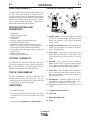
CONTROLS AND SETTINGS
1. ON/OFF Switch – In the ON position the machine
is ready for normal operation. All system control
circuits are activated. OFF position deactivates
control circuits.
2. Output Current Knob-Adjusts the cutting current
supplied by the machine according to the thick-
ness of material/speed.
3. Green LED – Turns ON when input voltage is
applied within normal range – blinks slowly when
input voltage goes above 130Vac, or below
95Vac.
4. Red LED – Turns ON when torch is triggered
Blinks quickly during 3 second safety pre-flow
prior to pilot arc ignition Blinks slowly if cutting arc
is not initiated after 3 second pilot arc ignition.
5. Yellow LED – Turns ON when the thermal protec-
tion is activated. Blinks slowly when the under
pressure protection is working (the pressure is
under 55 PSI, 3.8 Bar)
6. Air Regulator – Adjusts the input air pressure –
pull upward to unlock, press down to lock – nomi-
nal air pressure setting is 65 PSI, 4.5 Bar.
Note: Regulator should never be set above 87 PSI (6
Bar).
7. Compressed Air Connection
8. Input Cord
9. Work cable with clamp
10. Torch
2
4
5
3
9
10
1
6
7
8
USER RESPONSIBILITY
Variation such as plate chemistry, plate surface condi-
tion (oil, scale), plate thickness, preheat, quench,
gas type, gas flow rate and equipment may produce
results different than those expected. Some adjust-
ments to procedures may be necessary to compen-
sate for unique individual conditions. Test all proce-
dures duplicating actual field conditions.
DESIGN FEATURES AND
ADVANTAGES
• Light weight
• Continuous output control
• Indicator LEDs
• Cooling fan
• Rapid arc restrike for cutting across gaps
• 3 second arc delay for safety
•
Adjustable air pressure regulator with locking feature
•
Part-in-place verification for safety and proper operation
• Thermostatic protection with thermal indication
• Air inlet filter with water purge button to protect air
path and torch
• Lighted ON/OFF switch
• High input voltage protection
CUTTING CAPABILITY
The PLASMA 20 is rated for 20A @ 40% duty cycle.
The unit is designed to cut up to 3/8” inch mild steel,
but has the capability to cut other metals such as
stainless and aluminum (travel speed will vary).
TORCH CONSUMABLES
The torch consumables consist of an Electrode, Gas
Distributor Ring, Nozzle, and Shield Cup. The con-
sumable parts must be placed in the correct order and
secured properly for the unit to operate.
LIMITATIONS
• For indoor use only.
• Do not exceed output current and duty cycle rating
of machine. Do not use the PLASMA 20 for pipe
thawing.
• Do not power with generators or engine drives.

B-3
OPERATION
B-3
CHECKING AIR QUALITY
To check air quality, deactivate the torch (post-flow)
and place a welding filter lens in front of the torch. Any
oil or moisture in the air will be visible on the lens. DO
NOT initiate pilot arc while checking air quality.
When preparing to cut, position the machine as close
to the work as possible. Make sure you have all
materials needed to complete the job and have taken
all safety precautions. It is important to follow these
operating steps each time you use the machine.
• COMPRESSED AIR
The PLASMA 20 requires compressed air to be
attached to the unit. The input air pressure mini-
mum must be 72.5 PSI, 5 Bar and must not exceed
150 PSI, 10.3 Bar. An air regulator is included with
the unit with optimum pressure setting set to 65
PSI, 4.5 Bar.
The unit is also equipped with an air filter which cap-
tures water and oil vapor. The vapor collected can
be drained out of the bottom of the unit by turning
the drain button. The unit will not operate if the
input air pressure is below 55 PSI, 3.8 Bar.
Three Position Drain knob: (See Figure B.1)
1. Open
2. Open when no air pressure, closed when air pres-
sure.
3. Closed
CUTTING WITH A HAND TORCH
• Turn the main power and the machine power switch
on.
- The fan should start.
- The pre-charge circuit will operate for 3 seconds,
then the green "Power" LED should turn on.
• Be sure that the work lead is clamped to the work-
piece before cutting.
• Set the output current control knob at maximum
position for higher cutting speed and less dross for-
mation. Reduce the current, if desired to reduce the
kerf (cut) width, heat affected zone or travel speed
as required.
PLASMA 20
CUTTING OPERATIONS
BEFORE CUTTING
ELECTRIC SHOCK CAN KILL.
Disconnect input power by removing
the plug from the receptacle before
assembling or disassembling torch
parts, or torch and lead assemblies.
------------------------------------------------------------------------
Check and follow instructions listed in the “Safety and
Installation” section of this manual.
TORCH PARTS
Check the torch for proper assembly. Install proper
torch parts for the desired application (refer to the
Torch Consumable Parts Selection Section).
NOTE: The power supply will not operate unless the
torch shield cup is fully seated against the PIP
(Parts in Place) pins in the torch head.
INPUT POWER
Check the power source for proper input voltage.
Make sure the power source meets circuit protection
and wiring requirements.
Plug in power cord to supply input power to the unit.
GROUND CABLE
Check for a solid ground cable connection to the
workpiece.
AUTOMATIC PURGE SYSTEM
Place the ON/OFF switch to the ON position. If the
line voltage is OK, the green LED will turn on. Activate
the torch trigger to initiate air purge. There will be a 3
second delay to remove any condensation that may
have accumulated in the torch and air lines while the
system was shut down. When the air purge (Air safety
time) is complete, pilot arc will be initiated.
FIGURE B.1
WARNING
KNOB

B-4
OPERATION
B-4
NOTE: For better torch control, it is acceptable to let
the nozzle drag along the work piece surface. This
will shorten nozzle life. Also, it is acceptable to place
a non-conductive torch guide on the work piece in
order to achieve a cleaner cut
• When the trigger is released, the arc will stop.
- The gas will continue to flow for 20 seconds of
postflow. If the trigger is activated within this time
period, the pilot arc will restart after the 3 second
delay.
• If the dross is difficult to remove, reduce the cutting
speed. High speed dross is more difficult to remove
than low speed dross.
• The right side of the cut is more square than the left
as viewed along the direction of travel.
• Clean spatter and scale from the nozzle frequently.
Parts in place:
• Check the assembly of the torch consumables. If
they are not properly in place, the machine will not
start. Make sure that the shield cup is hand
tight. Do not use pliers or over tighten.
• Check the conditions of the inside of the nozzle. If
debris has collected, rub the electrode on the inside
bottom of the nozzle to remove any oxide layer that
may have built up. Refer to the “Routine
Maintenance Section".
• Check the condition of the electrode. If the end has
a crater-like appearance, replace it along with the
nozzle. The maximum wear depth of the electrode
is approximately .062”. A green and erratic arc will
indicate definite electrode failure and the electrode
should be replaced immediately.
• Replace the nozzle when the orifice exit is eroded
away or oval shaped.
ELECTRIC SHOCK CAN KILL.
Disconnect input power by removing
the plug from the receptacle before
assembling or disassembling torch
parts, or torch and lead assemblies.
------------------------------------------------------------------------
• If the machine does not reset or continues to trip,
consult the Troubleshooting Section.
• Use the proper cutting procedures referred to in
Procedure Recommendations.
PLASMA 20
• When ready to cut, place the torch near the work,
make certain all safety precautions have been taken
and pull the trigger.
- The air will flow for a preflow time of 3 seconds
and the pilot arc will start.
- The pilot arc will run for 3.0 seconds and shut off
unless the arc is brought in contact with the work
and the arc is transferred. Avoid excessive pilot
arc time by transferring the arc to the workpiece
quickly.
- When the arc is brought within 1/8” - 1/4" from
the work piece: the arc will transfer, the current
will ramp to the setting on the control panel, and
the cut can last indefinitely (or until the duty cycle
of the unit is exceeded).
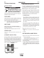
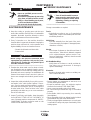
• Pierce the work piece by slowly lowering the torch
onto the metal at a 30
0
angle away from the opera-
tor. This will blow the dross away from the torch noz-
zle. Slowly rotate the torch to vertical position as the
arc becomes deeper.
NOTE: Graphics shown are for understanding torch
angles for best results – the distances from the work
piece are exaggerated. In actual operation, the noz-
zle should be held just above the work piece surface.
• Keep moving while cutting. Cut at a steady speed
without pausing. Maintain the cutting speed so that
the arc lag is 10° to 20° behind the travel direction.
•
Use a 5° - 15° leading angle in the direction of the cut.
• Finish the cut to be made and release the trigger.
3030
0
0
VERVERTICAL ANGLETICAL ANGLE
FOR CUTTINGFOR CUTTING
CUT
90
0
TORCH AT 30
0
ANGLE
TO PIERCE
ROTATE TO
90
0
ANGLE TO CUT
Direction of Travel
5° - 15°
10° - 20°
Arc Lag
Leading Angle
WARNING

B-5
OPERATION
B-5
OPERATING FAULTS
During cutting operations performance faults may
arise, such as:
• Insufficient penetration:
too high cutting speed;
torch is tilted;
piece is too thick;
cutting current is too low;
torch parts are worn out;
non-genuine Manufacturer’s parts.
• Interruption of the cutting arc:
cutting speed too slow;
excessive distance between torch and work
piece;
Input Voltage too low-reduce output current;
torch parts are worn out;
non-genuine Manufacturer’s parts;
poor work cable connection/disconnected.
• Excessive slag/dross:
too low cutting speed (bottom dross);
too high cutting speed (top dross);
excessive distance between torch and work
piece;
cutting current too low;
torch parts are worn out;
non-genuine Manufacturer’s parts.
• Tilted cutting (not perpendicular):
torch position not correct;
asymmetric wear of nozzle hole and/or
incorrect assembly of the torch parts.
• Excessive wear of nozzle and electrodes:
air pressure too low;
exceeding system capability (material too
thick);
contaminated air (humidity/oil);
excessive pilot arc ignitions in the air;
improperly assembled torch;
torch nozzle contacting workpiece;
damaged or loose torch head components;
non-genuine Manufacturer’s parts.
PLASMA 20
PILOT ARC DISCUSSION
The PLASMA 20 has a smooth, continuous pilot arc. The
pilot arc is only a means of transferring the arc to the work-
piece for cutting. Repeated pilot arc starts, in rapid succes-
sion, is not recommended as these starts will generally
reduce consumable life. Occasionally, the pilot arc may
sputter or start intermittently. This is aggravated when the
consumables are worn or the air pressure is too high.
Always keep in mind that the pilot arc is designed to transfer
the arc to the workpiece and not for numerous starts without
cutting.
When the pilot arc is started, a slight impulse will be felt in
the torch handle. This occurrence is normal and is the
mechanism which starts the plasma arc. This impulse can
also be used to help troubleshoot a "no start" condition.
S
HEILD CUP
NOZZLE
ELECTRODE
T
ORCH HEAD
A
SSEMBLY
GAS DIFFUSER RING
FIGURE B.2
ELECTRIC SHOCK CAN KILL.
Disconnect input power by removing
the plug from the receptacle before
assembling or disassembling torch
parts, or torch and lead assemblies.
--------------------------------------------------------------------------------
WARNING
Be sure the operator is equipped with proper gloves,
clothing, eye and ear protection. Make sure no part of
the operator’s body comes in contact with the work
piece while the torch is activated.
Sparks from the cutting process can cause dam-
age to coated, painted, and other surfaces such as
glass, plastic and metal.
NOTE: Handle torch cable with care and protect
it from damage.
------------------------------------------------------------------------
TORCH CONSUMABLE PARTS
SELECTION
To change the torch consumable parts use the follow-
ing procedure:
NOTE: The nozzle, gas distributor, and electrode are
held in place by the shield cup. Position the torch with
the shield cup facing upward
to prevent these parts
from falling out when the cup is removed.
1. Unscrew and remove the shield cup from the Torch
Head Assembly. Figure B.2 Consumable Parts.
2. Remove the nozzle, gas distributor, and electrode.
3. Install the electrode, gas distributor and nozzle.
4. Hand tighten the shield cup until it is seated on the
torch head. If resistance is felt when installing the
cup, check the threads before proceeding.
CAUTION

D-1
MAINTENANCE
D-1
PLASMA 20
PERIODIC MAINTENANCE
Change consumables as required.
Torch:
• Periodically according to use, or if experiencing
cutting faults, inspect consumable parts associat-
ed with the plasma arc.
Shield Cup:
• Unscrew manually from the head of the torch.
Clean thoroughly and replace if damaged (burns,
distortions or cracks).
Nozzle:
• Check wear of plasma arc thru-hole and inner &
outer surfaces. If thru-hole is widened compared
to it’s original diameter, replace nozzle. If sur-
faces are particularly oxidized, clean them with
extra fine sand paper.
Air Distribution Ring:
• Verify there are no burns or cracks and that air-
flow holes are not obstructed. If damaged,
replace immediately.
Electrode:
• Replace electrode when crater on emitting sur-
face is about .08”(2mm).
• Before making any adjustments to the torch, let it
cool the entire post-flow time.
• Except for particular cases, it is advised to replace
electrode and nozzle AT THE SAME TIME.
• Insure correct assembly order of torch parts.
• Be careful that gas distributor ring is assembled
properly.
• Reassemble shield cup screwing it on manually
(hand tighten)
• Never assemble shield cup without having included
gas distributor ring and nozzle beforehand.
• Timely and appropriate maintenance on torch parts
is essential for safety and proper functionality of the
cutting system.
ELECTRIC SHOCK can kill.
• Have an qualified person service
this equipment.
• Disconnect input power by removing
plug from receptacle before assem-
bling or disassembling torch parts,
or torch and lead assemblies.
• Do not touch electrically hot parts.
----------------------------------------------------------------------
ROUTINE MAINTENANCE
1. Keep the cutting or gouging area and the area
around the machine clean and free of combustible
materials. No debris should be allowed to collect
which could obstruct air flow to the machine.
2. Every 3-4 months or so, the machine should be
cleaned with a low pressure airstream. Keeping the
machine clean will result in cooler operation and
higher reliability. Be sure to clean these areas:
- Printed circuit boards and heat sinks
- Power switch
• When using a low pressure airstream, wear
appropriate eye protection. Only use dry com-
pressed air for cleaning. Do not point the jet of
air at the electronic circuits.
------------------------------------------------------------------------
3. Examine the sheet metal case for dents or break-
age. Repair the case as required. Keep the case in
good condition to insure that high voltage parts are
protected and correct spacings are maintained. All
external sheet metal screws must be in place to
insure case strength and electrical ground continu-
ity.
4. Inspect the cable periodically for any slits or punc-
ture marks in the cable jacket. Replace if neces-
sary. Check to make sure that nothing is crushing
the cable and blocking the flow of air through the
air tube inside. Also, check for kinks in the cable
periodically and relieve any so as not to restrict the
flow of air to the torch.
5. Inspect Torch Body and Handle, keep thoroughly
clean WITHOUT THE USE OF SOLVENTS. In
case of damage replace components for SAFETY
CONDITIONS. If repairs cannot be made on site
contact a local field service shop.
WARNING
ELECTRIC SHOCK CAN KILL.
• Turn off machineand disconnect
input power by removing the plug
from the receptacle switch before
tightening, cleaning or replacing
consumables.
----------------------------------------------------------------------------
WARNING
CAUTION
WARNING

D-2
MAINTENANCE
D-2
PLASMA 20
COMPRESSED AIR FILTER
The unit is supplied with a filter for the compressed air
and fitted with a manual drain for condensation. (Drain
is located on the bottom of the filter). Purge periodical-
ly to remove the water in the filter by opening the drain
knob.
Do not use solvents to clean the filter; use soapy
water only.

E-1
TROUBLESHOOTING
E-1
PLASMA 20
HOW TO USE TROUBLESHOOTING GUIDE
WARNING
ELECTRIC SHOCK CAN KILL.
• Turn off machine and disconnect
input power by removing the plug
from the receptacle switch before
tightening, cleaning or replacing
consumables.
----------------------------------------------------------------------------
WARNING
This Troubleshooting Guide is provided to help you
locate and repair possible machine malfunctions.
Simply follow the three-step procedure listed below.
Step 1. LOCATE PROBLEM (SYMPTOM).
Look under the column labeled “PROBLEM (SYMP-
TOMS)”. This column describes possible symptoms
that the machine may exhibit. Find the listing that
best describes the symptom that the machine is
exhibiting.
Step 2. POSSIBLE CAUSE.
The second column labeled “POSSIBLE CAUSE” lists
the obvious external possibilities that may contribute
to the machine symptom.
Step 3. RECOMMENDED COURSE OF ACTION
This column provides a course of action for the
Possible Cause, generally it states to contact your
local Lincoln Authorized Field Service Facility.
If you do not understand or are unable to perform the
Recommended Course of Action safely, contact your
local Lincoln Authorized Field Service Facility.
Service and Repair should only be performed by Lincoln Electric Factory Trained Personnel.
Unauthorized repairs performed on this equipment may result in danger to the technician and
machine operator and will invalidate your factory warranty. For your safety and to avoid Electrical
Shock, please observe all safety notes and precautions detailed throughout this manual.
__________________________________________________________________________
If for any reason you do not understand the test procedures or are unable to perform the tests/repairs safely, contact your
Local Lincoln Authorized Field Service Facility for technical troubleshooting assistance before you proceed.
CAUTION

E-2
TROUBLESHOOTING
E-2
PLASMA 20
Observe all Safety Guidelines detailed throughout this manual
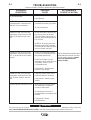
PROBLEMS
(SYMPTOMS)
POSSIBLE
CAUSE
RECOMMENDED
COURSE OF ACTION
GREEN LED OFF, Fan not operat-
ing. No Input Power.
GREEN LED ON, YELLOW
Overtemperature / under pressure
LED ON. Unit is overheated.
GREEN LED ON, YELLOW Over
temperature / under pressure LED
blinks. No air flow in purge or pre-
flow.
GREEN LED ON, YELLOW Over
temperature / under pressure LED
OFF, no air flow when torch switch
pressed.
GREEN LED ON, YELLOW Over
temperature / under pressure LED
OFF. Air flows, Pilot arc does not
start.
Torch has pilot arc but does not cut.
1. Plug unit into 115V outlet.
2. Reset Breaker.
1. Make sure the unit has not been
operated beyond duty cycle limits.
2. Air Flow obstructed.
1. Air not connected or pressure too
low. Check source for at least
72.5 PSI (5 Bar) during purge or
pre-flow, adjust air pressure to 65
PSI (4.5 Bar).
2. Air filter or air line blocked, torch
blocked. Replace filter cartridge.
Check that air line and torch leads
are free of twists and kinks.
1. Shield cup not properly installed
on torch. Check that shield cup is
fully seated against torch.
2. Faulty Torch Switch or Parts
Assembly in torch holder. Refer to
“Operations Section” (Torch
Consumable Parts).
3. Faulty Main PC Board Repair /
Replace Power Supply.
1. Faulty torch parts. Inspect torch
parts and replace if necessary.
2. Faulty main PC Board. Repair /
replace.
1. Work lead not connected. Make
sure work lead is connected
securely to bare metal.
2. AC input power too low. Use
shortest distance to breaker panel
possible.
3. Faulty Main PC Board.
Repair/Replace.
If all recommended possible areas of
misadjustment have been checked
and the problem persists, Contact
your local Authorized Field
Service Facility.
If for any reason you do not understand the test procedures or are unable to perform the tests/repairs safely, contact your
Local Lincoln Authorized Field Service Facility for technical troubleshooting assistance before you proceed.
CAUTION

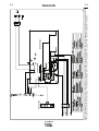
F-1
DIAGRAMS
F-1
PLASMA 20
NOTE: This diagram is for reference only. It may not be accurate for all machines covered by this manual. The specific diagram for a particular code is pasted inside
the machine on one of the enclosure panels. If the diagram is illegible, write to the Service Department for a replacement. Give the equipment code number.
5
INVERTER BOARD
DISPLAY BOARD
CONTROL BOARD
11/ 07
La page est en cours de chargement...
La page est en cours de chargement...
La page est en cours de chargement...
La page est en cours de chargement...
-
 1
1
-
 2
2
-
 3
3
-
 4
4
-
 5
5
-
 6
6
-
 7
7
-
 8
8
-
 9
9
-
 10
10
-
 11
11
-
 12
12
-
 13
13
-
 14
14
-
 15
15
-
 16
16
-
 17
17
-
 18
18
-
 19
19
-
 20
20
-
 21
21
-
 22
22
-
 23
23
-
 24
24


Lincoln Electric IM10006 Manuel utilisateur
- Catégorie
- Système de soudage
- Taper
- Manuel utilisateur
dans d''autres langues
- English: Lincoln Electric IM10006 User manual
Documents connexes
-
Lincoln Electric Pro-Cut 125 Manuel utilisateur
-
Lincoln Electric 10475 Manuel utilisateur
-
-
-
-
-
-
-
Lincoln Electric VANTAGE 500 Mode d'emploi
-