
4
1
2
3
543
6
7
7
8
9
10 11 12 13 14 15 16
5
4
3
2
1
5
1 2
8
6
6
7
© Copyright 2019 ATEN
®
International Co., Ltd.
ATEN and the ATEN logo are trademarks of ATEN International Co., Ltd. All rights reserved. All
other trademarks are the property of their respective owners.
Part No. PAPE-1223-R60G Printing Date: 07/2019
4 x 2 True 4K Presentation Matrix Switch with
Scaling, DSP, and HDBaseT-Lite
Quick Start Guide
VP1421
VP1421 4 x 2 True 4K Presentation Matrix Switch with Scaling, DSP, and HDBaseT-Lite
www.aten.com
ATEN VanCryst
™
B
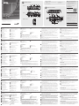
Package Contents
1 VP1421 4 x 2 True 4K Presentation Matrix Switch
1 IR Receiver
1 IR Remote Control
4 3-pole Terminal Blocks
2 5-pole Terminal Blocks
1 Power Adapter
1 User Instructions
Hardware Installation
Front View
Rear View
IR Remote Control
A
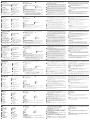
Hardware Review
A
Hardware Review
Front View
1
MIC In Port
2
Phantom Power Switch
3
MIC Volume Control
4
Overall Volume Control
Rear View
1
Ethernet Port
2
IR Receiver Port
3
RS-232 Serial Port
4
Contact In Port
5
LED Out Port
6
Audio In Port
7
Audio Out Ports
- Stereo Line Out Port
- Optical Audio Out Port
8
Cable Tie Slot
• To connect a video source via a video extender, connect the VP1421’s
HDBaseT In Port to the HDBaseT Out Port of a Tx device using an
Ethernet cable.
2
• To connect an HDMI source, connect the device to the VP1421’s HDMI In
Port using an HDMI cable. You can connect up to two HDMI sources.
3
Connect the unit to displays.
• Use an HDMI cable to connect the unit to an HDMI display.
• To set up a display at a distance, use an Ethernet cable to connect the
VP1421’s HDBaseT Out Port to the HDBaseT In Port of a suitable Rx
device, to which the display is connected.
2
4
(Optional) To supply independent audio, connect an audio source device (e.g.
media player) or a microphone to the Audio In Port.
5
(Optional) Connect an active speaker to the Audio Out Port.
6
(Optional) To control the VP1421 via a contact closure switch, connect
the switch to the Contact In and LED Out Ports using the provided 5-pole
Terminal Blocks.
7
(Optional) To confi gure the unit’s settings via RS-232 commands, connect a
hardware controller, e.g. ATEN Control Box, to the RS-232 Serial Port using
the provided 3-pole Terminal Block.
8
(Optional) To allow access to the web interface, use an Ethernet cable to
connect the Ethernet Port of the unit to a network switch.
9
(Optional) To control the VP1421 using an IR remote control, connect the IR
receiver to the IR Receiver Port.
10
Plug the power adapter to the Power Jack. Optionally use the cable tie slot
and a cable tie to hold the power cable in place.
11
Press the Power Pushbutton to power on the unit.
12
Power on all the connected devices.
Note
1. Do not omit this step. Proper grounding helps prevent damage to the unit
from power surges or static electricity.
2. The VP1421 supports bidirectional RS-232 and IR pass-through.
Operation
You can operate the unit using the front-panel pushbuttons, IR remote control,
RS-232 serial controller, or the web interface. See the user manual for detailed
information. To log in the web interface, use the default IP address 192.168.0.60
and the default credentials (administrator/password).
14
Output/Display A (HDMI Out Port)
15
Output/Display B
- HDBaseT Out Port
- RS-232 Serial Port
- IR Port
IR Remote Control
1
On/Off
2
Source
3
Display
4
Mute
B
Hardware Installation
1
Use a grounding wire to ground the unit by connecting one end to the
grounding terminal, and the other end to a suitable grounded object.
1
2
Connect the unit to video sources.
• To connect a VGA source, use a VGA cable and a stereo audio cable to
connect the source to the Source 1 Ports.
4
2
3
3
5
4
1
8
9
10
6
7
Internet/
LAN
Media Player
A
B
VE802R
VE802T
Rear View
Front View
9
PoH Control Switch
10
Power Jack
11
Source 1
- VGA In Port
- Stereo Audio In Port
12
Source 2
- HDBaseT In Port
- RS-232 Serial Port
- IR Port
13
Source 3, 4
- HDMI In Ports
5
Display Selection Pushbuttons
6
Source Selection Pushbuttons
7
Power Pushbutton
8
Mode Pushbutton
Support and Documentation Notice
All information, documentation, fi rmware,
software utilities, and specifi cations contained in
this package are subject to change without prior
notifi cation by the manufacturer.
To reduce the environmental impact of our
products, ATEN documentation and software can
be found online at
http://www.aten.com/download/
Technical Support
www.aten.com/support
이 기기는 업무용(A급) 전자파적합기기로서 판매자 또는 사용자는 이 점을
주의하시기 바라며, 가정외의 지역에서 사용하는 것을 목적으로 합니다.
Scan for
more information
EMC Information
FEDERAL COMMUNICATIONS COMMISSION INTERFERENCE
STATEMENT:
This equipment has been tested and found to comply with the limits
for a Class A digital device, pursuant to Part 15 of the FCC Rules.
These limits are designed to provide reasonable protection against
harmful interference when the equipment is operated in a commercial
environment. This equipment generates, uses, and can radiate radio
frequency energy and, if not installed and used in accordance with
the instruction manual, may cause harmful interference to radio
communications. Operation of this equipment in a residential area
is likely to cause harmful interference in which case the user will be
required to correct the interference at his own expense.
FCC Caution: Any changes or modifi cations not expressly approved by
the party responsible for compliance could void the user's authority to
operate this equipment.
Warning: Operation of this equipment in a residential environment
could cause radio interference.
Suggestion: Shielded twisted pair (STP) cables must be used with the
unit to ensure compliance with FCC & CE standards.
This device complies with Part 15 of the FCC Rules. Operation is subject
to the following two conditions:(1) this device mat not cause harmful
interference, and(2) this device must accept any interference received,
including interference that may cause undesired operation.
Important. Before proceeding, download the Installation and
Operation Manual by visiting the website, www.aten.com and
navigating to the product page. The manual includes important
warnings, loading specifi cations and grounding instructions.
16
Grounding Terminal
5
Mode
6
Volume Down
7
Volume Up
Commutateur matriciel de présentation True 4K 4 x 2 VP1421 avec scaler, DSP, et HDBaseT-Lite
www.aten.com
VP1421 4 x 2 True 4K Präsentation Matrix Switch mit Skalierung, DSP und HDBaseT-Lite
www.aten.com
Conmutador de matriz de presentación 4K real VP1421 4 x 2 con escalado, DSP y HDBaseT-Lite
www.aten.com
VP1421 - презентационный матричный коммутатор 4x2, c DSP, поддержкой True 4K, масштабирования и HDBaseT-Lite
www.aten.com
Switch matrix per presentazioni 4 x 2 True 4K VP1421 con scalatura, DSP, e HDBaseT-Lite
www.aten.com
A
Description de l’appareil
Vue de devant
1
Port d'entrée MIC
2
Interrupteur Phantom
3
Contrôle du volume MIC
4
Contrôle du volume général
Vue de derrière
1
Port Ethernet
2
Port récepteur IR
3
Port série RS-232
4
Port d'entrée de contact
5
Port de sortie LED
6
Port d'entrée audio
7
Ports de sortie audio
- Port de sortie ligne stéréo
- Port de sortie audio optique
8
Fente de l'attache de câbles
• Pour connecter une source vidéo via un système d'extension vidéo,
connectez le port d’entrée HDBaseT du VP1421 au port de sortie
HDBaseT d’un appareil Tx device à l’aide d’un câble Ethernet.
2
• Pour connecter une source HDMI, connectez l’appareil au port d’entrée
HDMI du VP1421 à l’aide d’un câble HDMI. Vous pouvez connecter
jusqu’à deux sources HDMI.
3
Connecter l’unité aux écrans.
• Utilisez un câble HDMI pour connecter l’unité à un écran HDMI.
• Pour confi gurer un écran à distance, utilisez un câble Ethernet pour
connecter le port de sortie HDBaseT du VP1421 au port d'entrée
HDBaseT d’un appareil Rx approprié, auquel l’écran est connecté.
2
4
(Facultatif) Pour fournir un audio indépendant, connectez un appareil source
audio (tel qu’un lecteur multimédia) ou un microphone au port d’entrée audio.
5
(Facultatif) Connectez un haut-parleur actif au port de sortie audio.
6
(Facultatif) Pour contrôler le VP1421 via un interrupteur à contact sec,
connectez l’interrupteur aux ports d’entrée contact et de sortie LED en utili-
sant les borniers à 5 pôles fournis.
7
(Facultatif) Pour confi gurer les paramètres de l’unité via les commandes RS-
232, connectez un contrôleur matériel, par ex. un boîtier de contrôle ATEN,
au port série RS-232 en utilisant le bornier à 3 pôles fourni.
8
(Facultatif) Pour permettre l’accès à l’interface Web, utilisez un câble Ethernet
afi n de connecter le port Ethernet de l’unité à un commutateur réseau.
9
(Facultatif) Pour contrôler le VP1421 en utilisant une télécommande IR,
connectez le récepteur IR au port du récepteur IR.
10
Branchez l’adaptateur secteur sur la prise d’alimentation. Utilisez, de
manière facultative, l’emplacement de l’attache-câble et un attache-câble
pour maintenir le câble d’alimentation en place.
11
Appuyez sur le bouton-poussoir d’alimentation de l’unité.
12
Allumez tous les appareils connectés.
Remarque
1. Ne négligez pas cette étape. Une mise à la terre appropriée aide à prévenir
les dommages à l'appareil due aux surtensions ou à l'électricité statique.
2. Le VP1421 prend en charge la transmission bidirectionnelle RS-232 et IR.
Fonctionnement
Vous pouvez utiliser l’unité à l’aide des boutons-poussoirs du panneau avant, de
la télécommande IR, du contrôleur série RS-232 ou de l’interface Web. Consultez
le manuel de l'utilisateur pour des informations détaillées. Pour vous connecter à
l’interface Web, utilisez l’adresse IP par défaut 192.168.0.60 et les informations de
connexion par défaut (administrator/password).
14
Sortie/Écran A (port de sortie HDMI)
15
Sortie/Écran B
- Port de sortie HDBaseT
- Port série RS-232
- Port IR
Télécommande IR
1
Marche/Arrêt
2
Source
3
Affi chage
4
Muet
B
Installation du matériel
1
Utilisez un fi l de mise à la terre pour relier l'unité en connectant une
extrémité à la borne de mise à la terre et l'autre extrémité à un objet mis à
la terre approprié.
1
2
Connectez l’unité aux sources vidéo.
• Pour connecter une source VGA, utilisez un câble VGA et un câble audio
stéréo pour connecter la source aux Ports 1 de la source.
9
Commutateur de commande PoH
10
Fiche d’alimentation
11
Source 1
- Port d’entrée VGA
- Port d’entrée audio stéréo
12
Source 2
Ports d’entrée HDBaseT
- Port série RS-232
- Port IR
13
Source 3, 4
- Ports d'entrée HDMI
5
Boutons de sélection de l'affi chage
6
Boutons de sélection de la source
7
Bouton d'alimentation
8
Bouton-poussoir de mode
5
Mode
6
Réduire le volume
7
Augmenter le volume
16
Borne de mise à la terre
A
Hardware Übersicht
Ansicht von vorne
1
MIC Eingang
2
Ein/Aus-Schalter (Phantomspeisung)
3
MIC Lautstärkeregelung
4
Gesamtlautstärkeregelung
Ansicht von hinten
1
Ethernet Anschluss
2
IR Empfangsanschluss
3
RS-232 serieller Anschluss
4
Kontakt Eingang
5
LED Ausgang
6
Audio-Eingang
7
Audio-Ausgänge
- Stereo Line Ausgang
- Optischer Audio Ausgang
8
Kabelbinder Schacht
mit dem HDBaseT Ausgang eines Tx Geräts.
2
• Um eine HDMI-Quelle anzuschließen, verbinden Sie das Gerät über ein
HDMI-Kabel mit dem HDMI Eingang des VP1421. Sie können bis zu zwei
HDMI Quellen anschließen.
3
Schließen Sie das Gerät an die Anzeigen an.
• Verwenden Sie ein HDMI-Kabel, um das Gerät an eine HDMI Anzeige
anzuschließen.
• Um eine Anzeige aus der Ferne einzurichten, verbinden Sie den HDBaseT
Ausgang des VP1421 über ein Ethernetkabel mit dem HDBaseT Eingang
eines geeigneten Rx Geräts, an das die Anzeige angeschlossen ist.
2
4
(Optional) Um unabhängiges Audio zu liefern, schließen Sie ein Audioquellgerät
(z.B. einen Mediaplayer) oder ein Mikrofon an den Audio Eingang an.
5
(Optional) Verbinden Sie einen aktiven Lautsprecher mit dem Audio Ausgang.
6
(Optional) Um den VP1421 über einen Kontaktschließer zu steuern,
verbinden Sie den Switch über die mitgelieferten 5-poligen Anschlussblök-
ke mit den Anschlüssen Kontakt Eingang und LED Ausgang.
7
(Optional) Um die Einstellungen des Geräts über RS-232 Befehle zu konfi gurieren,
schließen Sie einen Hardware Controller, z.B. die ATEN Kontrollbox, über den
mitgelieferten 3-poligen Anschlussblock an den seriellen RS-232 Anschluss an.
8
(Optional) Um den Zugriff auf die Webschnittstelle zu ermöglichen,
verwenden Sie ein Ethernet-Kabel, um den Ethernet-Anschluss des Geräts
mit einem Netzwerk Switch zu verbinden.
9
(Optional) Um den VP1421 mit einer IR-Fernbedienung zu steuern,
verbinden Sie den IR-Empfänger mit dem IR-Empfängeranschluss.
10
Schließen Sie das Netzteil an die Netzbuchse an. Verwenden Sie optional
den Kabelbinderschlitz und einen Kabelbinder, um das Netzkabel an
seinem Platz zu halten.
11
Drücken Sie die Ein-/Aus-Taste, um das Gerät einzuschalten.
12
Schalten Sie alle angeschlossenen Geräte ein.
Hinweis
1. Lassen Sie diesen Schritt nicht aus. Eine ordnungsgemäße Erdung hilft bei
der Vermeidung von Schäden am Gerät durch Stromspitzen oder statischer
Elektrizität.
2. Der VP1421 unterstützt bidirektionales RS-232 und IR Passthrough.
Bedienung
Sie können das Gerät über die Tasten an der Vorderseite, die IR-Fernbedienung, den
seriellen RS-232 Controller oder die Webschnittstelle bedienen. Weitere Einzelheiten
fi nden Sie im Benutzerhandbuch. Verwenden Sie bei der ersten Anmeldung die
Standard IP-Adresse 192.168.0.60 und die Standard Anmeldeinformationen
(administrator/password).
14
Ausgang/Anzeige A (HDMI Ausgang)
15
Ausgang/Anzeige B
- HDBaseT Ausgang
- RS-232 serieller Anschluss
- IR Anschluss
IR Fernbedienung
1
Ein/Aus
2
Quelle
3
Anzeige
4
Ton aus
B
Hardwareinstallation
1
Verwenden Sie ein Erdungskabel, um das Gerät zu erden, indem Sie ein
Ende mit der Erdungsklemme und das andere Ende mit einem geeigneten
geerdeten Objekt verbinden.
1
2
Schließen Sie das Gerät an Videoquellen an.
•
Um eine VGA-Quelle anzuschließen, verwenden Sie ein VGA-Kabel und ein
Stereo Audiokabel, um die Quelle mit den Quelle 1 Anschlüssen zu verbinden.
• Um eine Videoquelle über eine Videoverlängerung anzuschließen,
verbinden Sie den HDBaseT Eingang des VP1421 über ein Ethernetkabel
9
PoH Steuerungsschalter
10
Netzanschluss
11
Quelle 1
- VGA-Eingang
- Stereo Audio-Eingang
12
Quelle 2
- HDBaseT Eingang
- RS-232 serieller Anschluss
- IR Anschluss
13
Quelle 3, 4
- HDMI-Eingang
5
Anzeigeauswahl-Drucktasten
6
Quellenauswahl-Drucktasten
7
Ein-/Aus-Drucktaste
8
Modusdrucktaste
5
Modus
6
Leiser
7
Lauter
16
Erdungsanschluss
A
Presentación del hardware
Vista frontal
1
Puerto de entrada MIC
2
Interruptor de alimentación fantasma
3
Control de volumen MIC
4
Control de volumen total
Vista posterior
1
Puerto Ethernet
2
Puerto receptor IR
3
Puerto serie RS-232
4
Puerto de entrada de contacto
5
Puerto de salida LED
6
Puerto de entrada de audio
7
Puertos de salida de audio
- Puerto de salida de línea estéreo
- Puerto de salida de audio óptico
8
Ranura de abrazadera para cables
conecte el puerto de entrada HDBaseT VP1421 al puerto de salida
HDBaseT de un dispositivo Tx utilizando un cable Ethernet.
2
• Si desea conectar una fuente HDMI, conecte el dispositivo al puerto de
entrada HDMI de VP1421 utilizando un cable HDMI. Puede conectar
hasta dos fuentes HDMI.
3
Conecte la unidad a pantallas.
• Utilice un cable HDMI para conectar la unidad a una pantalla HDMI.
•
Para confi gurar una pantalla a una distancia, utilice un cable Ethernet para
conectar el puerto de salida HDBaseT del VP1421 al puerto de entrada
HDBaseT de un dispositivo Rx adecuado, al que está conectada la pantalla.
2
4
(Opcional) Para suministrar audio independiente, conecte un dispositivo
de fuente de audio (p. ej., un reproductor multimedia) o un micrófono, al
puerto de entrada de audio.
5
(Opcional) Conecte un altavoz activo al puerto de salida de audio.
6
(Opcional) Para controlar el VP1421 a través de un interruptor de cierre
de contacto, conecte el interruptor a los puertos de entrada de contacto y
salida LED utilizando los bloques de terminales de 5 polos suministrados.
7
(Opcional) Para ajustar la confi guración de la unidad a través de comandos
RS-232, conecte un controlador de hardware (p. ej., una caja de control ATEN) al
puerto serie RS-232 utilizando el bloque de terminales de 3 polos suministrado.
8
(Opcional) Para permitir el acceso a la interfaz web, utilice un cable
Ethernet para conectar el puerto Ethernet de la unidad a un conmutador
de red.
9
(Opcional) Para controlar el VP1421 mediante un mando a distancia por
infrarrojos, conecte el receptor de infrarrojos al puerto del receptor de infrarrojos.
10
Conecte el adaptador de alimentación a la toma de alimentación. También
puede utilizar una abrazadera para cables y la ranura correspondiente para
mantener el cable de alimentación en su sitio.
11
Pulse el botón de encendido para encender la unidad.
12
Encienda todos los dispositivos conectados.
Nota
1. No omita este paso. Una conexión correcta a tierra protege a la unidad de
la electricidad estática y de las subidas de tensión.
2. El VP1421 admite pasarela bidireccional por RS-232 e infrarrojos.
Funcionamiento
Puede manejar la unidad a través de los botones del panel delantero, el mando a
distancia por infrarrojos, el controlador serie RS-232 o la interfaz web. Para obtener
información detallada, consulte el manual de usuario. Para iniciar sesión en la
interfaz web, utilice la dirección IP predeterminada 192.168.0.60 y los credenciales
predeterminados (administrator/password).
14
Salida/Pantalla A (puerto de salida HDMI)
15
Salida/Pantalla B
- Puerto de salida HDBaseT
- Puerto serie RS-232
- Puerto de infrarrojos
Mando a distancia por infrarrojos
1
Encendido/apagado
2
Fuente
3
Pantalla
4
Silencio
B
Instalación de hardware
1
Utilice un cable de tierra para conectar la unidad a tierra conectando un
extremo al terminal de tierra y el otro extremo a un objeto conectado a
tierra correctamente.
1
2
Conecte la unidad a las fuentes de vídeo.
• Si desea conectar una fuente VGA, utilice un cable VGA y un cable de
audio estéreo para conectar la fuente a puertos de entrada 1.
• Si desea conectar una fuente de vídeo a través de un alargador de vídeo,
9
Interruptor de control PoH
10
Conector de alimentación
11
Fuente 1
- Puerto de entrada VGA
- Puerto de entrada de audio estéreo
12
Fuente 2
- Puerto de entrada HDBaseT
- Puerto serie RS-232
- Puerto de infrarrojos
13
Fuente 3, 4
- Puertos de entrada HDMI
5
Botones de selección de pantalla
6
Botones de selección de fuente
7
Botón de encendido
8
Pulsador de modo
5
Modo
6
Bajar volumen
7
Subir volumen
16
Toma de tierra
A
Descrizione hardware
Vista anteriore
1
Porta ingresso MIC
2
Interruttore alimentazione Phantom
3
Controllo volume MIC
4
Controllo volume generale
Vista posteriore
1
Porta Ethernet
2
Porta ricevitore IR
3
Porta seriale RS-232
4
Porta ingresso contatto
5
Porta uscita LED
6
Porta ingresso audio
7
Porta uscita audio
- Porta uscita linea stereo
- Porta uscita audio ottico
8
Slot fermacavi
dispositivo Tx utilizzando un cavo Ethernet.
2
• Per collegare una sorgente HDMI, collegare il dispositivo alla porta
ingresso HDMI del VP1421 usando un cavo HDMI. È possibile collegare
fi no a due sorgenti HDMI.
3
Collegare l'unità agli schermi.
• Usare un cavo HDMI per collegare l'unità a uno schermo HDMI.
• Per confi gurare uno schermo a distanza, usare un cavo Ethernet per
collegare la porta di uscita HDBaseT del VP1421 alla porta di ingresso
HDBaseT di un dispositivo Rx adeguato al quale è collegato lo schermo.
2
4
(Opzionale) Per inviare audio indipendente, collegare un dispositivo sorgente audio
(ad esempio un lettore multimediale) o un microfono alla porta ingresso audio.
5
(Opzionale) Collegare un altoparlante attivo alla porta di uscita audio.
6
(Opzionale) Per controllare il VP1421 tramite uno switch alloggiamento di
contatto, collegare lo switch all'ingresso contatto e alle porte uscita LED
usando i blocchi terminali a 5 poli in dotazione.
7
(Opzionale) Per confi gurare le impostazioni dell'unità tramite i comandi RS-232,
collegare il controller hardware, ad esempio una Scatola di controllo ATEN, alla
porta seriale RS-232 usando il blocco terminale a 3 poli in dotazione.
8
(Opzionale) Per consentire l'accesso all'interfaccia web, usare il cavo
Ethernet per collegare la porta Ethernet dell'unità a uno switch di rete.
9
(Opzionale) Per collegare il VP1421 usando un telecomando IR, collegare il
ricevitore IR alla porta Ricevitore IR.
10
Collegare l'adattatore di alimentazione al jack di alimentazione. È anche
possibile usare lo slot fermacavi e un fermacavi per tenere il cavo di
alimentazione in posizione.
11
Premere il pulsante push di accensione per accendere l'unità.
12
Accendere tutti i dispositivi collegati.
Nota
1. Non ignorare questo passaggio. Una messa a terra corretta aiuta a evitare
danni all'unità derivanti da sbalzi elettrici o elettricità statica.
2. Il VP1421 supporta il pass-through RS-232 e IR bidirezionale.
Funzionamento
È possibile utilizzare l'unità usando i pulsanti push del pannello frontale, telecomando
IR, controller seriale RS-232 o interfaccia web. Per le informazioni dettagliate
consultare il manuale utente. Per accedere all'interfaccia web, usare l'indirizzo IP
predefi nito 192.168.0.60 e le credenziali predefi nite (administrator/password).
14
Uscita/Display A (porta uscita HDMI)
15
Uscita/Display B
- Porta uscita HDBaseT
- Porta seriale RS-232
- Porta IR
Telecomando IR
1
On/Off
2
Sorgente
3
Display
4
Disattiva audio
B
Installazione hardware
1
Utilizzare un fi lo di messa a terra per mettere a terra l'unità collegando un'e-
stremità al morsetto di messa a terra e l'altra estremità ad un oggetto idoneo.
1
2
Collegare l'unità alle sorgenti video.
• Per collegare una sorgente VGA, usare un cavo VGA e un cavo audio
stereo per collegare la sorgente alla porta Sorgente 1.
• Per collegare una sorgente video mediante una prolunga video, collegare
la porta ingresso HDBaseT del VP1421 alla porta uscita HDBaseT di un
9
Interruttore controllo PoH
10
Jack di alimentazione
11
Sorgente 1
- Porta ingresso VGA
- Porta ingresso audio stereo
12
Sorgente 2
- Porta ingresso HDBaseT
- Porta seriale RS-232
- Porta IR
13
Sorgente 3, 4
- Porte ingresso HDMI
5
Selezione pulsanti Display
6
Pulsanti di selezione della sorgente
7
Pulsante di alimentazione
8
Pulsante push modalità
5
Modalità
6
Volume giù
7
Volume su
16
Terminale di messa a terra
A
Обзор аппаратного обеспечения
Вид спереди
1
Гнездо микрофонного входа
2
Выключатель фантомного питания
3
Регулятор громкости микрофона
4
Общий регулятор громкости
Вид сзади
1
Порт Ethernet
2
Порт приемника ИК-сигналов
3
Последовательный порт RS-232
4
Порт Contact In
5
Порт LED Out
6
Гнездо звукового входа
7
Разъемы звукового выхода
- Разъем стереофонического
линейного выхода
- Оптический разъем звукового
выхода
8
Слот для кабельной стяжки
• Для подключения источника HDMI подключите устройство к порту
HDMI In коммутатора VP1421 с помощью кабеля HDMI. Подключить
можно не более двух источников HDMI.
3
Подключите устройство к дисплеям.
• С помощью кабеля HDMI подключите устройство к дисплею HDMI.
•
Для удаленной настройки дисплея с помощью кабеля Ethernet
подключите порт HDBaseT Out коммутатора VP1421 к порту HDBaseT
In подходящего приемника (Rx), к которому подключен дисплей.
2
4
(Необязательно) Для подключения независимого звука подключите
к порту Audio In устройство-источник звука (например, медиаплеер)
или микрофон.
5
(Необязательно) Подключите активный динамик к разъему Audio Out.
6
(Необязательно) Для управления VP1421 через коммутатор с
замыкающими контактами подключите коммутатор к портам Contact In
и LED Out, используя прилагаемые 5-контактные клеммные колодки.
7
(Необязательно) Для настройки параметров устройства с помощью
команд RS-232 подключите аппаратный контроллер, например, блок
управления ATEN, к последовательному порту RS-232 с помощью
прилагаемой 3-контактной клеммной колодки.
8
(Необязательно) Для доступа к веб-интерфейсу подключите порт
Ethernet устройства к сетевому коммутатору с помощью кабеля Ethernet.
9
(Необязательно) Для управления VP1421 с помощью ИК-пульта дистан-
ционного управления подключите ИК-приемник к порту ИК-приемника.
10
Подключите адаптер питания к гнезду питания. При необходимости
для закрепления кабеля питания используйте слот для кабельной
стяжки и кабельную стяжку.
11
Нажмите кнопку питания, чтобы включить устройство.
12
Включите питание на всех подключенных устройствах.
Примечание
1. Не пропускайте этот шаг. Надлежащее заземление защищает
устройство от повреждений, вызываемых скачками напряжения и
статическим электричеством.
2. VP1421 поддерживает двунаправленную передачу через порт
RS-232 и сквозную передачу сигналов управления через ИК-порт.
Эксплуатация
Управлять устройством можно с помощью кнопок на передней панели, ИК-
пульта дистанционного управления, последовательного контроллера RS-232
или через веб-интерфейс. Подробную информацию см. в руководстве
пользователя. Для входа в веб-интерфейс введите используемые по умолчанию
IP-адрес 192.168.0.60 и учетные данные (administrator/password).
14
Выход/дисплей A (порт HDMI Out)
15
Выход/дисплей B
- Порт HDBaseT Out
- Последовательный порт RS-232
- ИК-порт
ИК-пульт ДУ
1
Вкл/Выкл
2
Источник
3
Дисплей
4
Без звука
B
Установка аппаратного обеспечения
1
С помощью заземляющего провода заземлите блок, подсоединив
один конец провода к заземляющей клемме, а другой — к подходя-
щему заземленному предмету.
1
2
Подключите устройство к источникам видеосигнала.
• Для подключения источника сигнала VGA используйте кабель
VGA, а для подключения источника к разъемам Источник 1 -
стереофонический звуковой кабель.
•
Для подключения источника видео через удлинитель видеосигналов
подключите порт HDBaseT In коммутатора VP1421 к порту HDBaseT
Out передатчика (Tx) с помощью кабеля Ethernet.
2
9
Управляющий переключатель PoH
10
Разъем питания
11
Источник 1
- Входной разъем VGA
- Разъем стереофонического
звукового входа
12
Источник 2
- Порт HDBaseT In
-
Последовательный порт RS-232
- ИК-порт
13
Источник 3, 4
- Порты HDMI In
5
Кнопки выбора дисплея
6
Кнопки выбора источника
7
Кнопка питания
8
Кнопка выбора режима
5
Режим
6
Уменьшение громкости
7
Увеличение громкости
16
Клемма заземления
La page est en cours de chargement...
-
 1
1
-
 2
2


dans d''autres langues
- italiano: ATEN VP1421 Guida Rapida
- English: ATEN VP1421 Quick start guide
- español: ATEN VP1421 Guía de inicio rápido
- Deutsch: ATEN VP1421 Schnellstartanleitung
- русский: ATEN VP1421 Инструкция по началу работы
- português: ATEN VP1421 Guia rápido
- polski: ATEN VP1421 Skrócona instrukcja obsługi
- 日本語: ATEN VP1421 クイックスタートガイド
- Türkçe: ATEN VP1421 Hızlı başlangıç Kılavuzu
Documents connexes
-
ATEN VP1420 Guide de démarrage rapide
-
ATEN VE3912T Guide de démarrage rapide
-
-
ATEN VC1280 Guide de démarrage rapide
-
ATEN VS0801HB Guide de démarrage rapide
-
ATEN VM5404H Guide de démarrage rapide
-
ATEN VC182 Guide de démarrage rapide
-
ATEN VM3909H Guide de démarrage rapide
-
ATEN CE820R Guide de démarrage rapide
-