LG LFXS28566M Guide d'installation
- Catégorie
- Frigos
- Taper
- Guide d'installation

13INSTALLATION
ENGLISH
INSTALLATION
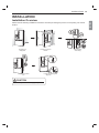
Installation Overview
3OHDVHUHDGWKHIROORZLQJLQVWDOODWLRQLQVWUXFWLRQV¿UVWDIWHUSXUFKDVLQJWKLVSURGXFWRUWUDQVSRUWLQJLWWRDQRWKHU
location.
Unpacking the
Refrigerator
Choosing the Proper
Location
Disassembling/
Assembling
Connecting the Water
Line
Leveling and Door
Alignment
CAUTION
xConnect to potable water supply only.

14 INSTALLATION
Unpacking the Refrigerator
WARNING
xUse two or more people to move and install the
refrigerator. Failure to do so can result in back
injury or other injury.
x7KHUHIULJHUDWRULVKHDY\3URWHFWWKHÀRRUZKHQ
moving the refrigerator for cleaning or service.
Always pull the refrigerator straight out when
moving it. Do not wiggle or walk the refrigerator
ZKHQWU\LQJWRPRYHLWDVÀRRUGDPDJHFRXOG
occur.
x.HHSÀDPPDEOHPDWHULDOVDQGYDSRUVVXFKDV
gasoline, away from the refrigerator. Failure to
GRVRFDQUHVXOWLQ¿UHH[SORVLRQRUGHDWK
NOTE
xRemove tape and any temporary labels from
your refrigerator before using. Do not remove any
warning labels, the model and serial number label,
or the Tech Sheet that is located under the front of
the refrigerator.
xTo remove any remaining tape or glue, rub the area
briskly with your thumb. Tape or glue residue can
also be easily removed by rubbing a small amount
of liquid dish soap over the adhesive with your
¿QJHUV:LSHZLWKZDUPZDWHUDQGGU\
xDo not use sharp instruments, rubbing alcohol,
ÀDPPDEOHÀXLGVRUDEUDVLYHFOHDQHUVWRUHPRYH
tape or glue. These products can damage the
surface of your refrigerator.
xReinstall or adjust shelves as needed. Refrigerator
shelves are installed in the shipping position.
Reinstall shelves according to your individual
storage needs.
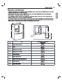
Choosing the Proper
Location
Water
Water supply must be easily connected for the
automatic icemaker.
NOTE
xThe water pressure must be 20 - 120 psi or 138 -
827 kPa or 1.4 - 8.4 kgf/cm2. If the refrigerator is
installed in an area with low water pressure (below
20 psi or 138 kPa or 1.4 kgf/cm2), you can install a
booster pump to compensate for the low pressure.
Electricity
Use an individual, grounded outlet:115 Volts, 60 Hz,
AC, 15 Amps minimum.
Flooring
To avoid noise and vibration, the unit must be
LQVWDOOHGDQGOHYHOHGRQDVROLGO\FRQVWUXFWHGÀRRU,I
required, adjust the leveling legs to compensate for
WKHXQHYHQQHVVRIWKHÀRRU
NOTE
xInstalling on carpeting, soft tile surfaces, a platform
or weakly supported structure is not recommended.
Ambient Temperature
Install this appliance in an area where the
temperature is between 55 °F (13 °C) and 110 °F
(43 °C).
If the temperature around the appliance is too low or
high, cooling ability may be adversely affected.


16 INSTALLATION
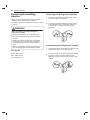
Removing/Assembling
Handles
xWhen moving the refrigerator through a narrow
opening, removing the doors is preferred.
xThe appearance of the handles may vary from what
is shown.
WARNING
When assembling or disassembling the
refrigerator handles:
x*UDVSWKHKDQGOH¿UPO\WRDYRLGGURSSLQJLW
xDo not swing the handle into nearby people or
animals.
xMake sure that the bracket hole of the handle
¿WVSURSHUO\LQWRWKHVWRSSHUEROWRIWKHGRRU
$VVHPEOHWKHVHWVFUHZVWR¿[WKHKDQGOHLQWR
place.
xMake sure that there is not a gap between the
door and handle after assembling the handle.
Tools Needed
3/32 in. Allen wrench
1/8 in. Allen wrench
1/4 in. Allen wrench
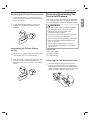
Removing the Refrigerator Handles
1Loosen the set screws (1) with a 3/32 in. Allen
wrench and remove the handle.
2Loosen the mounting fasteners (2) that connect
to the refrigerator door and handle using a 1/4
in. Allen wrench, and remove the mounting
fasteners.
Assembling the Refrigerator Handles
1Assemble the mounting fasteners (1) at both ends
of the handle with a 1/4 in. Allen wrench.
23ODFHWKHKDQGOHRQWKHGRRUE\¿WWLQJWKHKDQGOH
footprints over the mounting fasteners and
tightening the set screws (2) with a 3/32 in. Allen
wrench.

17INSTALLATION
ENGLISH
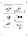
Removing the Freezer Drawer Handle
1Loosen the set screws (1) located on the lower
side of the handle with a 1/8 in. Allen wrench and
remove the handle.
2Loosen the mounting fasteners (2) with a 1/4
in. Allen wrench, and remove the mounting
fasteners.
Assembling the Freezer Drawer
Handle
1Assemble the mounting fasteners (1) at both ends
of the handle with a 1/4 in. Allen wrench.
23ODFHWKHKDQGOHRQWKHGRRUE\¿WWLQJWKHKDQGOH
footprints over the mounting fasteners and
tightening the set screws (2) with a 1/8 in. Allen
wrench.
Removing/Assembling the
Doors and Drawers
If the entrance door is too narrow for the refrigerator
to pass through, remove the refrigerator doors and
move the refrigerator sideways through the doorway.
WARNING
xUse two or more people to remove and install
the refrigerator doors and freezer drawer.
xDisconnect the electrical supply to the
refrigerator before installing.
xDo not put hands, feet or other objects into the
air vents or bottom of the refrigerator.
xBe careful when handling the hinge and stopper.
xRemove food and bins before detaching the
doors and drawers.
xDo not hold the handle when removing or
replacing the doors and drawer as the handle
may come off.
Tools Needed
3/32 in. Allen wrench
1/8 in. Allen wrench
1/4 in. Allen wrench
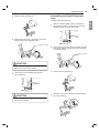
Removing the Left Refrigerator Door
1The water supply is connected to the upper
right part of the rear surface of the refrigerator.
Remove the ring in the joint area. Hold the water
supply connection and gently push the collet (1)to
detach the water supply line (2) as shown.

18 INSTALLATION
2Remove the screw (1) from the hinge cover at the
top of the refrigerator. Lift the hook (not visible),
located at the bottom of the front side of the cover
ZLWKDÀDWKHDGVFUHZGULYHU
3Remove the cover and pull out the tube (1).
Disconnect all wire harnesses (2). Unscrew the
ground wire (3).
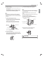
4Rotate the hinge lever counterclockwise (1). Lift
the top hinge (2) free of the hinge lever latch.
(1) (2)
Hinge Lever Latch
CAUTION
xWhen lifting the hinge free of the latch, be careful
that the door does not fall forward.
5Lift the door from the middle hinge pin and
remove the door.
CAUTION
xPlace the door, inside facing up, on a
nonscratching surface.
NOTE
Disassembling/Assembling the Water Lines
Collet
Tube
Insert line
Clip (Correct)
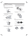
Removing the Right Refrigerator
Door
1Remove the top hinge cover screw (1). Lift
the hook (not visible), located at the bottom of
WKHIURQWVLGHRIWKHFRYHUZLWKDÀDWKHDG
screwdriver.

19INSTALLATION
ENGLISH
2Detach the wire harness (1).
3Rotate the hinge lever (1) clockwise. Lift the top
hinge (2) free of the hinge lever latch.
Hinge Lever Latch
CAUTION
xWhen lifting the hinge free of the latch, be careful
that the door does not fall forward.
4Lift the door from the middle hinge pin and
remove the door.
CAUTION
xPlace the door, inside facing up, on a
nonscratching surface.
Assembling the Right Refrigerator
Door
,QVWDOOWKHULJKWVLGHGRRU¿UVW
1Make sure that the plastic sleeve is inserted in
the bottom of the door. Lower the door onto the
PLGGOHKLQJHSLQDVVKRZQLQWKH¿JXUH
2Fit the hinge (1) over the hinge lever latch and slot
it into place. Rotate the lever (2) counterclockwise
to secure the hinge.
Hinge Lever Latch
3Connect the wire harness (1).
4Place the cover (1) in its place. Insert and tighten
the cover screw (2).

20 INSTALLATION
Assembling the Left Refrigerator
Door
Install the left refrigerator door after the right door is
installed.
1Make sure that the plastic sleeve is inserted in
the bottom of the door. Install the refrigerator door
onto the middle hinge.
2Fit the hinge (1) over the hinge lever latch and
slot it into place. Rotate the lever clockwise (2)
and fasten the hinge.
Hinge Lever Latch
3Connect all the wire harnesses.
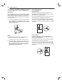
4Push the water supply tube into the hole on the
top case and pull it through the backplate.
5Hold the water supply connection and gently push
in the collet (1) to connect the water supply line
(2) as shown. Insert the tube at least 5/8 inch (15
mm) into the connector. Insert the clip on the joint
to fasten the tube in place.
Collet
6Place the cover (1) in place. Insert and tighten the
cover screw (2).
NOTE
Disassembling/Assembling the Water Lines
Collet
Tube
Insert line
Clip (Correct)
Gently press the collet and insert the tube until only
one line shows on the tube.
(Correct) (Incorrect)

21INSTALLATION
ENGLISH
Removing the Freezer Drawers
For models with two freezer drawers, remove both
drawers in the same way.
The Pullout Drawer located above the freezer drawer
is not shown for clarity.
WARNING
7RUHGXFHWKHULVNRIHOHFWULFVKRFNLQMXU\WR
persons, and death, follow basic precautions,
including the following:
xUse two or more people to remove and install
the refrigerator doors and freezer drawer.
xBe careful of sharp hinges on both sides of the
drawer.
xWhen you lay the drawer down, be careful not to
GDPDJHWKHÀRRU
xDo not sit or stand on the freezer drawer.
xTo prevent accidents, keep children and pets
away from the drawer. Do not leave the drawer
open. If the Durabase® storage bin is removed
IURPWKHIUHH]HUGUDZHUWKHUHLVVXI¿FLHQWVSDFH
for a small child or pet to crawl inside.
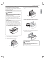
1Pull the drawer open to full extension.
2Gently lift and pull out the ice bin.
3Lift the front of the drawer up, then pull it straight
out.
4Remove the Durabase basket from the rails.
Remove the screws from the rails at both ends.
5Grip both sides of the drawer and pull it up to
remove it from the rails.
CAUTION
xDo not hold the handle when removing or
replacing the drawer. The handle may come off,
causing personal injury.

22 INSTALLATION
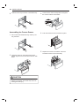
6Hold both rails and push them in simultaneously.
Assembling the Freezer Drawer
1Pull out both rails simultaneously, until they are
fully extended.
2Grasp the drawer on each side and hook the
drawer supports into the rail tabs located on both
sides.
CAUTION
xDo not hold the handle when removing or
replacing the drawer. The handle may come off,
causing personal injury.
3/RZHUWKHGRRULQWRLWV¿QDOSRVLWLRQDQGWLJKWHQ
the screws located on both sides.
4Push the drawer back until it clicks into place.
5Replace the ice bin in the drawer. Insert the
Durabase basket in the rail assembly.

23INSTALLATION
ENGLISH
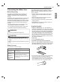
Connecting the Water Line
Before Beginning
This water line installation is not covered by the
refrigerator warranty. Follow these instructions
carefully to minimize the risk of expensive water
damage.
,IQHFHVVDU\FDOODTXDOL¿HGSOXPEHUWRFRUUHFWZDWHU
hammer before installing the water supply line to
the refrigerator. Water banging in the pipes, or water
hammer in residential plumbing can cause damage
to refrigerator parts and lead to water leakage or
ÀRRGLQJ
xTurn the icemaker OFF if the refrigerator will be
used before the water line is connected.
xDo not install the icemaker tubing in areas where
the ambient temperatures fall below freezing.
WARNING
xConnect to potable water supply only.
CAUTION
xTo prevent burns and product damage, only
connect the refrigerator water line to a cold water
supply.
xWear eye protection during installation to prevent
injury.
Water Pressure
You will need a cold water supply.
Water Pressure
models with
ZDWHU¿OWHU
20–120 psi
(138 - 827 kPa)
where reverse
osmosis
ZDWHU¿OWUDWLRQ
system is
connected to
a cold water
supply
40–60 psi minimum to reverse
osmosis system (2.8 – 4.2 kgf/cm2,or
OHVVWKDQ±VHFRQGVWR¿OODFXSRI
7 oz capacity)
If the water pressure from the reverse osmosis
system is less than 20 psi or 138 kPa or 1.4 kgf/ cm2
WDNHVPRUHWKDQVHFRQGVWR¿OODFXSRIR]RU
198 cc capacity):
x&KHFNWRVHHLIWKHVHGLPHQW¿OWHULQWKHUHYHUVH
RVPRVLVV\VWHPLVEORFNHG5HSODFHWKH¿OWHULI
necessary.
xAllow the storage tank on the reverse osmosis
V\VWHPWRUH¿OODIWHUKHDY\XVDJH
xIf the water pressure remains low, call a licensed,
TXDOL¿HGSOXPEHU
xAll installations must be in accordance with local
plumbing code requirements.
Supplies Needed
xCopper or PEX Tubing, ¼ in. outer diameter, to
connect the refrigerator to the water supply. Be sure
both ends of the tubing are cut square. To determine
how much tubing you need, measure the distance
from the water valve on the back of the refrigerator
to the water supply pipe. Then, add 8 feet (2.4 m).
%HVXUHWKHUHLVVXI¿FLHQWH[WUDWXELQJDERXWIHHW
[2.4 m] coiled into 3 turns of about 10 in. [25 cm]
diameter) to allow the refrigerator to move out from
the wall after installation.
xPower drill.
xòLQRUDGMXVWDEOHZUHQFK
xFlat-blade and Phillips-head screwdrivers.
xTwo ¼ in. outer diameter compression nuts and
2 ferrules (sleeves) to connect the copper tubing to
the shutoff valve and the refrigerator water valve.
x,I\RXUH[LVWLQJFRSSHUZDWHUOLQHKDVDÀDUHG¿WWLQJ
at the end, purchase an adapter (available at
plumbing supply stores) to connect the water line
WRWKHUHIULJHUDWRU25FXWRIIWKHÀDUHG¿WWLQJZLWKD
WXEHFXWWHUDQGWKHQXVHDFRPSUHVVLRQ¿WWLQJ

24 INSTALLATION
xShutoff valve to connect to the cold water line.
The shutoff valve should have a water inlet with a
minimum inside diameter of 5/32 in. at the point of
connection to the COLD WATER LINE. Saddle-type
shutoff valves are included in many water supply
kits. Before purchasing, make sure a saddle-type
valve complies with your local plumbing codes.
NOTE
xA self-piercing saddle type water valve should not
be used.
Water Line Installation Instructions
WARNING
Electric Shock Hazard:
xWhen using any electrical device (such as a
power drill) during installation, be sure the device
is battery-powered, double-insulated or grounded
in a manner that will prevent the hazard of
electric shock.
Install the shutoff valve on the nearest frequently
used drinking water line.
1Shut off the main water supply.
Turn on the nearest faucet to relieve the pressure
on the line.
2Choose the valve location.
Choose a location for the valve that is easily
accessible. It is best to connect into the side of
a vertical water pipe. When it is necessary to
connect into a horizontal water pipe, make the
connection to the top or side, rather than at the
bottom, to avoid drawing off any sediment from
the water pipe.
3Drill the hole for the valve.
xDrill a ¼ in. hole in the water pipe using a sharp
bit. Remove any burrs resulting from drilling the
hole in the pipe. Be careful not to allow water
to drain into the drill. Failure to drill a ¼ in. hole
may result in reduced ice production or smaller
cubes.
NOTE
xThe hookup line cannot be white, plastic tubing.
Licensed plumbers must use only copper tubing
(NDA tubing #49595 or #49599) or Cross Link
Polyethylene (PEX) tubing.
4Fasten the shutoff valve.
Fasten the shutoff valve to the cold water pipe
with the pipe clamp.
Pipe Clamp
Saddle-Type
Shutoff Valve Vertical Cold
Water Pipe
NOTE
xCommonwealth of Massachusetts Plumbing Codes
248CMR shall be adhered to. Saddle valves are
illegal and use is not permitted in Massachusetts.
Consult with your licensed plumber.
5Tighten the pipe clamp.
Tighten the clamp screws until the sealing washer
begins to swell.
Pipe Clamp
Clamp Screw
Washer
Inlet End
NOTE
xDo not over tighten clamp or you may crush the
tubing.

25INSTALLATION
ENGLISH
6Route the tubing.
Route the tubing between the cold water line and
the refrigerator.
Route the tubing through a hole drilled in the wall
RUÀRRUEHKLQGWKHUHIULJHUDWRURUDGMDFHQWEDVH
cabinet) as close to the wall as possible.
NOTE
x%HVXUHWKHUHLVVXI¿FLHQWH[WUDWXELQJDERXWIW
coiled into three turns of about 10 in. diameter) to
allow the refrigerator to move out from the wall after
installation.
7Connect the tubing to the valve.
Place the compression nut and ferrule (sleeve)
for copper tubing onto the end of the tubing and
connect it to the shutoff valve.
Make sure the tubing is fully inserted into the
valve. Tighten the compression nut securely.
Saddle-Type
Shutoff Valve
Packing Nut
Outlet Valve
Compression Nut
Ferrule (sleeve)
8Flush out the tubing.
7XUQWKHPDLQZDWHUVXSSO\RQDQGÀXVKRXWWKH
tubing until the water is clear. Shut the water off at
the water valve after about one quart of water has
EHHQÀXVKHGWKURXJKWKHWXELQJ
9Connect the tubing to the refrigerator.
NOTE
xBefore making the connection to the refrigerator, be
sure that the refrigerator power cord is not plugged
into the wall outlet.
x5HPRYHWKHSODVWLFÀH[LEOHFDSIURPWKHZDWHU
valve.
xPlace the compression nut and ferrule (sleeve) onto
the end of the tubing as shown.
xInsert the end of the copper tubing into the
connection as far as possible. While holding the
WXELQJWLJKWHQWKH¿WWLQJ
Tubing Clamp
¼ in. Compression Nut
Ferrule (sleeve)
¼ in. Tubing
Refrigerator Connection
10 Turn the water on at the shutoff valve.
Tighten any connections that leak.
CAUTION
xCheck for leaks at all water line connections.

26 INSTALLATION
Leveling and Door Alignment
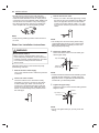
Leveling
The refrigerator has two front leveling legs. Adjust the
legs to alter the tilt from front-to-back or side-to side.
If the refrigerator seems unsteady, or the doors do
not close easily, adjust the refrigerator’s tilt using the
instructions below:
1Turn the leveling leg to the left to raise that side
of the refrigerator or to the right to lower it. It may
take several turns of the leveling leg to adjust the
tilt of the refrigerator.
NOTE
x$ÀDUHQXWZUHQFKZRUNVEHVWEXWDQRSHQHQG
ZUHQFKZLOOVXI¿FH'RQRWRYHUWLJKWHQ
2Open both doors and check to make sure that
they close easily. If the doors do not close easily,
tilt the refrigerator slightly more to the rear by
turning both leveling legs to the left. It may take
several more turns, and be sure to turn both
leveling legs the same amount.
Door Alignment
Standard Door
Both the left and right refrigerator doors have an
adjustable nut, located on the bottom hinge, to raise
and lower them to align properly.
If the space between the doors is uneven, follow the
instructions below to align the doors evenly:
Use the wrench (included with the owner's manual)
to turn the nut in the door hinge to adjust the height.
Turn the nut to the right to raise the door or to the left
to lower it.
Door-in-Door
The left refrigerator door has an adjustable nut,
located on the bottom hinge, to raise and lower the
door for proper alignment.
If the space between the doors is uneven, follow the
instructions below to align the left door:
Use the wrench (included with the owner's manual)
to turn the nut in the door hinge to adjust the height.
Turn the nut to the right to raise the door or to the left
to lower it.

27INSTALLATION
ENGLISH
The right refrigerator door does not have an
adjustable nut.
If the space between the doors is uneven, follow the
instructions below to align the right door:
1With one hand, lift up both the inner and outer
door sections of the right door to raise them at the
middle hinge. (It may be easier to lift it with the
doors open.)
2With the other hand, use pliers to insert the snap
ring on the middle hinge of the inner door section
as shown. Do not insert the ring on the hinge of
the outer door section.
3Insert additional snap rings until the right door is
aligned. (Two snap rings are provided with the
unit.)
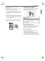
Turning on the Power
xAfter installing, plug the refrigerator’s power cord
into a 3-prong grounded outlet and push the
UHIULJHUDWRULQWRWKH¿QDOSRVLWLRQ
CAUTION
xConnect to a rated power outlet.
x+DYHDFHUWL¿HGHOHFWULFLDQFKHFNWKHZDOORXWOHW
and wiring for proper grounding.
xDo not damage or cut off the ground terminal of
the power plug.
Position the Refrigerator
xArrange the coil of tubing so that it does not vibrate
against the back of the refrigerator or against the
wall. Push the refrigerator back to the wall.
Start the Icemaker
xIf the water line is connected, set the icemaker
power switch to the ON position.
xThe icemaker will not begin to operate until it
reaches its operating temperature of 15 °F (–9 °C)
or below. It will then begin operation automatically if
the icemaker power switch is in the ON (I) position.
-
 1
1
-
 2
2
-
 3
3
-
 4
4
-
 5
5
-
 6
6
-
 7
7
-
 8
8
-
 9
9
-
 10
10
-
 11
11
-
 12
12
-
 13
13
-
 14
14
-
 15
15


LG LFXS28566M Guide d'installation
- Catégorie
- Frigos
- Taper
- Guide d'installation
dans d''autres langues
- English: LG LFXS28566M Installation guide