Frigidaire CFGS3035LS2 Installation Instructions Manual
- Catégorie
- Micro-ondes
- Taper
- Installation Instructions Manual
Ce manuel convient également à

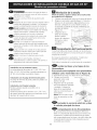
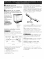
iNSTALLATiON AND SERVICE MUST BE PERFORMED BY A QUALiFiED iNSTALLER.
iMPORTANT: SAVE FOR LOCAL ELECTRICAL iNSPECTOR'S USE.
READ AND SAVE THESE iNSTRUCTiONS FOR FUTURE REFERENCE.
_ if the information in this manual is not followed exactly,
a fire or explosion may result causing property damage, personal injury
or death.
FOR YOUR SAFETY:
--Do not store or use gasoline or other flammable vapors and liquids in
the vicinity of this or any other appliance.
--WHAT TO DO IF YOU SMELL GAS:
* Do not try to light any appliance.
Do not touch any electrical switch; do not use any phone in your
building.
,, Immediately call your gas supplier from a neighbor's phone. Follow
the gas supplier's instructions.
, If you cannot reach your gas supplier, call the fire department.
--Installation and service must be performed by a qualified installer,
service agency or the gas supplier.
@
Refer to your serial plate for
applicable agency certification
Appliances Installed in the
state of Massachusetts:
ThisAppliancecanonly be installed
in the stateof Massachusettsby a
Massachusettslicensedplumber or
gasfitter.
Thisappliancemustbe installedwith
a three(3) foot / 36 in. long flexible
gasconnector•
A"T" handletype manualgasvalve
must be installedin the gassupply
line to this appliance•
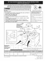
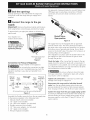
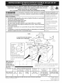
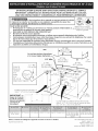
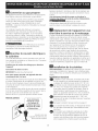
WALL 30" Min.
These surfaces (76.2 cm Min.)
should be _I
flat & leveled I _._._--
(hatched area):--% "_-_-'- i ----- _" _,
........ \ 30" Min. _/\ 13"
wz mvmln.\\ (76 2 cm) M n (see _ - ,_ ,
• " _ t44 cm)
= 5" Min. \\ Note 3) 18" Min.
1 ½" Max _ (12,_7,c,mM,in.), \\-_-=_._J (45.7 cm) Min.
Shave • Prom Wall I:iOtn bides _ _ ' .
(3.8cm Max.)
Raised
Edge ,_'_X ,, _ _'_4"__
Space _--_--___J_/ '
1 .1 T Lxac I/, '
f°ra31Y2" "_-'_ _/ e _-- ,,
(81 cm)Wide _ . _Jx . Approx• 17/8
j (4.8cm)
Cooktop. F /"__-_-'-_... JJh i
Locate Cabinet Doors1,, (2 5 c_) _ _ Aj__p:_ ....... //
Min. from Cutout Opening. _ __,_/ E -/ .............. /x,_
IMPORTANT" i _ ,___r _ /"24" Min.
Cabinet and " i 1 / (61 cm Min.)
countertop width i ii _ -- "
should match the _ E ,
. _ :_ Grounded Junction Box or Wall Outlet Should Be Located 8"
cutout width, ii i • . to 17" (20•3 cm to 43•2 cm) From Right Cabinet and 2" to
- __1 4" (5•1 cm to 10•2 cm) From Floor•
35 5/8" (90.5 cm) - 30" (76,2 cm) 31Y2" (80 cm) 28 5/16" (71,9 cm) 30_+1/16" (76,2_+0,15 cm)
36 5/8" (93cm)
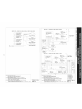
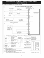
NOTE: Wiring diagram for these appliances are enclosed in this booklet.
Printed in United States
21 3/4" (55,2 cm) Min• 36 5/8" (93 cm) Max.
22 1/8" (56,2 cm) Max 35 5/8" (90.5 cm) Min.
24" (61 cm) Min• with
backguard
P/N318201685 (1007) Rev.A
English - pages 1-10
Espahol- p_iginas 11-20
Francois - pages 21-30
Wiring Diagrams - pages 31-32

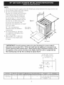
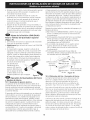
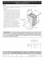
NOTE:
1. Do not pinch the power supply cord or the flexible gas conduit between the range and the wall.
2. Do not seal the range to the side cabinets.
3.24" (61 cm) minimum clearance
between the cooktop and the bottom 21%"i_' _:
of the cabinet when the bottom of 55..25 cm) _ _-_
wood or metal cabinet is protected _ f "C
by not less than ¼" (0.64 cm) flame __,_.
retardant millboard covered with not ___
less than No. 28 MSG sheet metal, Figure 1 __
0.015 ,,(0.4 mm) stainless steel, ,, _
0.024 (0.6 mm) aluminum, or 0.020 _
(0.5 mm)copper. _ _ A
/
30 (76.2 cm) minimum Door Open |
clearance when the cabinet is (see note 5)
unprotected. .
4. For cutouts beow 22 7/8"(58 1 _ t f
cm), appliance will slightly show _%"
• t / _j#
out of the cab,net. .. j ........... .:,__
5. Allow at least 19 ¼" (48.9 cm) _<_ ............
clearance for door depth when _ "-,,.
.t ,s open. _B "_"_'/
Side )anel
*IMPORTANT: To avoid cooktop cooktop (or glass) breakage for cutout width (E
dimension) of more than 30V_6" (76.4 cm), make sure the appliance is centered in the
counter opening while pushing into it. Raise leveling legs at maximum position, insert
the appliance in the counter and then level. Make sure the unit is supported by
the leveling legs not by the cooktop (or glass) itself.
22 7/8" (58.1 cm) min.
23 1/4" (59.05 cm) max.
,÷ (see Note 4) -_
1 1/8"
(2.86 cm)
FRONT
OF _ FRef_
CABINET
35 5/8" (90.5 cm) -
36 5/8" (93cm)
30" (76,2 cm) 31Y2" (80 cm) 28 5/16" (71,9 cm) 30_+1/16" (76,2_+0,15 cm) 21 3/4" (55,2 cm) Min.
22 1/8" (56,2 cm) Max
24" (61 cm) Min. with
backguard
36 5/8" (93 cm) Max.
35 5/8" (90.5 cm) Min.

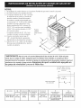
Important Notes to the Installer
1. Read all instructions contained in these installation
instructions before installing range.
2. Remove all packing material from the oven
compartments before connecting the gas and
electrical supply to the range.
3. Observe all governing codes and ordinances.
4. Be sure to leave these instructions with the consumer.
5. Note: For operation at 2000 ft. elevations above see
level, appliance rating shall be reduced by 4 percent
for each additional 1000 ft.
Important Note to the Consumer
Keep these instructions with your Use & Care Guide for
future reference.
IMPORTANT SAFETY
INSTRUCTIONS
Installation of this range must conform with local codes
or, in the absence of local codes, with the National Fuel
Gas Code ANSI Z223.1/NFPA .54-latest edition.
This range has been design certified by CSA
International. As with any appliance using gas and
generating heat, there are certain safety precautions you
should follow. You will find them in the Use and Care
Guide, read it carefully.
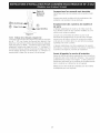
• Be sure your range is installed and grounded
properly by a qualified installer or service
technician.
• This range must be electrically grounded in
accordance with local codes or, in their absence,
with the National Electrical Code ANSI/NFPA No.
70--latest edition. See Grounding Instructions.
Before installing the range in an area covered
with linoleum or any other synthetic floor
covering, make sure the floor covering can
withstand heat at least 90°F above room
temperature without shrinking, warping or
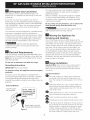
All ranges
can tip.
Injury to
persons
could result.
Install anti-
tip device
packed with
range.
To reduce the risk of
tipping of the range, the
range must be secured
by properly installed
anti-tip bracket provided
with the range. To
check if the bracket is
installed properly, grasp
the top rear edge of the
range and carefully tilt
it forward to make sure
the range is anchored.
discoloring. Do not install the range over carpeting
unless you place an insulating pad or sheet of 1/4"
(10,16 cm) thick plywood between the range and
carpeting.
Make sure the wall coverings around the range
can withstand the heat generated by the range.
• Do not obstruct the flow of combustion air at the
oven vent nor around the base or beneath the
lower front panel of the range. Avoid touching the
vent openings or nearby surfaces as they may become
hot while the oven is in operation. This range requires
fresh air for proper burner combustion.
Never leave children alone or
unattended in the area where an appliance is in
use. As children grow, teach them the proper, safe use
of all appliances. Never leave the oven door open when
the range is unattended.
Stepping, leaning or sitting on the
doors or drawers of this range can result in serious
injuries and can also cause damage to the range.
Do not store items of interest to children in
the cabinets above the range. Children could be
seriously burned climbing on the range to reach items.
To eliminate the need to reach over the surface
burners, cabinet storage space above the burners
should be avoided.
Adjust surface burner flame size so it does not
extend beyond the edge of the cooking utensil.
Excessiveflame is hazardous.
Do not use the oven as a storage space. This
creates a potentially hazardous situation.
Never use your range for warming or heating the
room. Prolonged use of the range without adequate
ventilation can be dangerous.
Do not store or use gasoline or other flammable
vapors and liquids near this or any other
appliance. Explosions or fires could result.
In the event of an electrical power outage, the surface
burners can be lit manually. To light a surface burner,
hold a lit match to the burner head and slowly turn
the Surface Control knob to LITE.Use caution when
lighting surface burners manually.
Reset all controls to the "off" position after using
a programmable timing operation.
FOR MODELS WITH SELF-CLEAN FEATURE:
• Remove broiler pan, food and other utensils
before self-cleaning the oven. Wipe up excess
spillage. Follow the precleaning instructions in the Use
and Care Guide.
Unlike the standard gas range, THIS COOKTOP
IS NOT REMOVABLE. Do not attempt to remove the
cooktop
3

Cabinet Construction
To eliminate the risk of cabinet burns
and fire, do not have cabinet storage space above the
range. If there is cabinet storage space above range,
reduce risk by installing a range hood that projects
horizontally a minimum of 5" (12.7 cm) beyond the
bottom of the cabinet.
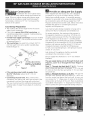
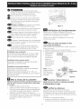
Countertop Preparation
• The cooktop sides of the range fit over the cutout
edge of your countertop.
• If you have a square finish (flat) countertop, no
countertop preparation is required. Cooktop sides lay
directly on edge of countertop.
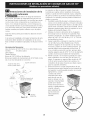
• Formed front-edged countertops must have molded
edge shaved flat 3/4" (1.9 cm) from each front corner
of opening (Figure 1).
• Tile countertops may need trim cut back 3/4"(1.9
cm) from each front corner and/or rounded edge
flattened (Figure 1).
(1.9cm)
I
J
(81cm)
Formed or tile countertop
trimmed _A" (1.9 cm) back at
front corners of countertop
opening.
Figure I
• If the existing cutout width is greater than
30-1116" (76,4 cm), reduce the 3A" (1.9 cm)
dimension.
• Countertop must be level, Place a level on the
countertop, first side to side, then front to back. If the
countertop is not level, the range will not be level.
The oven must be level for satisfactory baking results.
Cooktop sides of range fit over edges of countertop
opening.
m
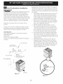
Provide an adequate Gas Supply
When shipped from the factory, this unit is designed
to operate on 4"(10,16 cm) water column (1.0 kPa)
Natural gas manifold pressure. A convertible pressure
regulator is connected to the range manifold and MUST
be connected in series with the gas supply line. If LID/
Propane conversion kit has been used, follow instructions
provided with the kit for converting the pressure
regulator to LP/Propane use.
Care must be taken during installation of range not to
obstruct the flow of combustion and ventilation air.
Forproper operation, the maximum inlet pressure to
the regulator should be no more than 14"(35,56 cm)
of water column pressure (3.5 kPa). The inlet pressure
to the regulator must be at least 1" (.25 kPa) greater
than the regulator manifold pressure setting. Examples:
If regulator is set for natural gas 4" (10,16 cm) manifold
pressure, inlet pressure must be at least 5"(12.60 cm);
if regulator has been converted for LP/Propane gas
10"(25,4 cm) manifold pressure, inlet pressure must be
at least 11 "(27,9 cm).
Leak testing of the appliance shall be conducted
according to the instructions in step 4.
The gas supply line should be 1/2"or 3A" I.D. (Interior
Diameter)
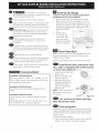
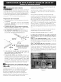
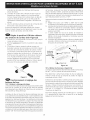
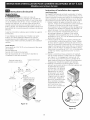
The gas supply piping can be through the back wall
(Figure 2, zone 1) or through the floor (Figure 2,
zone 2):
Zonel-Throu h the Back Wall 7"X6" -Thebest
place to have your gas line in is between 1" (2.5 cm) and
8" (20.3cm) from the floor and within 3" (7.6 cm) from
the center line.
Zone 2 - Through the Floor (~2" X 24") - The gas line
can also come through the floor within 12" (30.5 cm)
from the center line against the back wall. In case, you
can remove the "L" shape piece of metal at the bottom
metal portion at the back of the unit. There is absolutely
no problem removing this "L" shape piece of metal, it is
there to protect the gas line especially during transport.
4
gure 2

n
Seal the openings
Seal any openings in the wall behind the range and
in the floor under the range after gas supply line is
installed.
N
Connect the range to the gas
supply
Important: Remove all packing material and literature
from range before connecting gas and electrical supply.
To prevent leaks, put pipe joint sealant on all external
pipe threads.
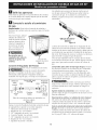
I
Your regulator is in
location shown below.
Do
not allow regulator to
rotate on pipe when
tightening fittings.
PRESSURE REGULATOR
LOCATION
Figure 3
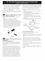
Connection to Pressure Regulator
T_already installed on the appliance.
Do not make the connection too tight.
The regulator is die cast. Overtightening may crack the
regulator resulting in a gas leak and possible fire or
explosion.
Manual GAS FLOW Pressure
Shutoff Flare __ Flare Regulator
Valve Union Union
1
Access
Off Connector
Cap
All connections must be wrench-tightened
Figure 4
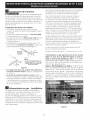
Assemble the flexible connector from the gas supply pipe
to the pressure regulator in the following order:
1. Manual shutoff valve (not included)
2. 1/2" nipple (not included)
3. 1/2" flare union adapter (not included
4. Flexible connector (not included)
5. 1/2" flare union adapter (not included
6. 1/2" nipple (not included)
7. Pressure regulator (included)
Use pipe-joint compound made for use with Natural and
LP/Propane gas to seal all gas connections. If flexible
connectors are used, be certain connectors are not
kinked.
Shutoff Valve =
Open position
Figure 5
The supply line must be equipped with an approved
manual shutoff valve. This valve should be located in
the same room as the range and should be in a location
that allows ease of opening and closing. Do not block
access to the shutoff valve. The valve isfor turning on or
shutting off gas to the appliance.
Once regulator is in place, open the shutoff valve in the
gas supply line. Wait a few minutes for gas to move
through the gas line.
Check for leaks. After connecting the range to the gas
supply, check the system for leaks with a manometer. If
a manometer is not available, turn on the gas supply and
use a liquid leak detector (or soap and water) at all joints
and connections to check for leaks.
Do not use a flame to check for leaks
from gas connections. Checking for leaks with a flame
may result in a fire or explosion.
Tighten all connections as necessary to prevent gas
leakage in the range or supply line.
Disconnect this range and its individual shutoff
valve from the gas supply piping system during any
pressure testing of the system at test pressures greater
than 1/2 psig (3.5 kPa or 14"(35,56 cm) water column).
Isolate the range from the gas supply piping system
by closing its individual manual shutoff valve during any
pressure testing of the gas supply piping system at test
pressures equal to or less than 1/2 psig (3.5 kPa or 14"
water column).

LP/Propane Gas Conversion
This appliance can be used with Natural gas or LP/
Propane gas. It is shipped from the factory for use with
natural gas.
If you wish to convert your range for use with LP/
Propane gas, use the supplied fixed orifices located in a
bag containing the literature marked "FOR LP/PROPANE
GAS CONVERSION." Follow the instructions packaged
with the orifices for surface, oven and broil burners
conversion.
The conversion must be performed by a qualified service
technician in accordance with the manufacturer's
instructions and all local codes and requirements. Failure
to follow these instructions could result in serious injury
or property damage. The qualified agency performing
this work assumes responsibility for the conversion.
Failure to make the appropriate
conversion can result in serious personal injury and
property damage.
Electrical Requirements
120 volt, 60 Hertz, properly grounded dedicated circuit
protected by a 15 amp circuit breaker or time delay fuse.
Note: Not recommended to be installed with a Ground
Fault Interrupt (GFI).
Do not use an extension cord with this range.
Grounding Instructions
IMPORTANT Pleaseread carefully.
For personal safety, this appliance must be properly
grounded.
The power cord of this appliance isequipped with a
3-prong (grounding) plug which mates with a standard
3-prong grounding wall receptacle (see Figure 6) to
minimize the possibility of electric shock hazard from the
appliance.
Preferred Method
Grounding type
wall receptacle
not, under any
circumstances, cut,
remove, or bypass
the grounding
prong.
Power supply cord with
3-prong grounding plug.
Figure 6
The wall receptacle and circuit should be checked by
a qualified electrician to make sure the receptacle is
properly grounded.
Where a standard 2-prong wall receptacle is installed,
it is the personal responsibility and obligation of the
consumer to have it replaced by a properly grounded
3-prong wall receptacle.
Do not, under any circumstances, cut or remove the
third (ground) prong from the power cord,
Disconnect electrical supply cord from
wall receptacle before servicing cooktop.
Moving the Appliance for
Servicing and Cleaning
Turn off the range line fuse or circuit breakers at the
main power source, and turn off the manual gas shut-off
valve. Make sure the range is cold. Remove the service
drawer (warmer drawer on some models) and open the
oven door. Lift the range at the front and slide it out
of the cut-out opening without creating undue strain
on the flexible gas conduit. Make sure not to pinch
the flexible gas conduit at the back of the range when
replacing the unit into the cut-out opening. Replace
the drawer, dose the door and switch on the electrical
power and gas to the range.
Range Installation
Important Note: Door removal is not a requirement for
installation of the range, but isan added convenience.
Refer to the Useand Care Guide for oven door removal
instructions.
Standard Installation
_The range cooktop (or cooktop glass) overlaps the
countertop at the sides and the range rests on the
floor. The cooktop (or cooktop glass) is 31Y2" (81 cm)
wide.
O
O
O
Install base cabinets 30" (76.2 cm) apart. Make sure
they are plumb and level before attaching cooktop.
Shave raised countertop edge to clear 31Y2" (81 cm)
wide range top rim.
Install cabinet doors 31 " (78.7 cm) min. apart so they
will not interfere with range door opening.
Cutout countertop exactly as shown on page 1.
A backguard kit can be ordered through Service Center.
To provide an optimum installation, the top surface of
the countertop must be level and flat (lie on the same
plane) around the 3 sides that are adjacent to range
cooktop. Proper adjustments to make the top flat
should be made or gaps between the countertop and
the range cooktop (or cooktop glass) may occur.

O
To reduce the risk of damaging
your appliance, do not handle or manipulate it by the
cooktop. Manipulate with care.
Position range in front of the cabinet opening.
Make sure that the cooktop (or cooktop glass) which
overhangs the countertop clears the countertop. If
necessary, raise the unit by lowering the leveling legs.
_J_ Level the range (see section 9). The floor where
the range is to be installed must be level. Follow
the instructions under "Leveling the Range-Models
Equipped with Leveling Legs".
O Adjust leveling legs so that the underside of
the cooktop (or cooktop glass) is sitting on the
countertop.
O Carefully screw in the back leveling leg until the
cooktop (or cooktop glass) overhang touches slightly
the countertop. The cooktop must not support the
unit.
il_ Slide the range into the cutout opening.
_Then carefully screw in the front two leveling legs
(similar to 12) until the cooktop (or cooktop glass)
overhang touches slightly the countertop.
_ll_ If the range is not level, pull unit out and readjust
leveling legs, or make sure floor is level.
If Accessories Needed
Installation With Backguard
The cutout depth of (21 3/4" (55.2 cm)Min., 22 1/8"
(56.2cm) Max.) needs to be increased to 24" (61 cm)
when installing a backguard.
Installation With End Panel
A End Panel kit can be ordered through a Service
Center.
Installation With Side Panels
A Side Panels kit can be ordered through a Service
Center.
Install cabinet doors 31 " (78.7 cm) min. apart so as
not to interfere with range door opening.
m
Leveling the Range
Level the range and set cooktop height before
installation in the cut-out opening.
1. Install an oven rack in the center of the oven.
2. Place a level on the rack (see Figure 7). Take 2
readings with the level placed diagonally in one
direction and then the other. Level the range, if
necessary, by adjusting the 4 leg levelers with a
wrench (see Figure
13). ®
3. Taking care to
not damage the
countertop, slide
range into cutout
opening and double
check for levelness.
Figure 7
Check Operation
Refer to the Use and Care Guide packaged with the
range for operating instructions and for care and
cleaning of your range.
Remove all packaging from the oven before testing.
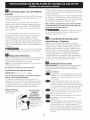
Install Burner Bases and Burner Caps
This range is equipped with sealed burners
as shown (see Figure 8). Bu_nercop
a. Unpack burner bases and f-_
burner caps.
b. Place burner bases over
each gas opening.
c. Make sure the burner
is properly aligned and
leveled. Place burner ................
capSburnerOverbases.appropriateBU_n_ ' ._
B_se
Z uPenlng
NOTE: There are no burner
adjustments necessary on
this range. _>_<..........
Electrode ,..L..... :igure 8
Turn on Electrical Power and Open
Main Shutoff Gas Valve
Check the Igniters
Operation of electric igniters should be checked after
range and supply line connectors have been carefully
checked for leaks, and range has been connected to
electric power.
To check for proper lighting:
A. Push in and turn a surface burner knob to the LITE
position. You will hear the igniter sparking.
7

B.Thesurfaceburnershouldlightwhengasisavailable
tothetopburner.Eachburnershouldlightwithin
four(4)secondsafterairhasbeenpurgedfrom
supplylines.Visuallycheckthatburnerhaslit.
c.Oncetheburnerlights,thecontrolknobshouldbe
rotatedoutoftheLITEposition.
Thereareseparateignitiondevicesforeachburner.Try
eachknobseparatelyuntilallburnervalveshavebeen
checked.
Adjust the "LOW" Setting of Surface
Burner Valves (see Figure 9)
a.Pushinandturneachcontrolto LITEuntilburner
ignites.
b.QuicklyturnknobtoLOWESTPOSITION.
c.Ifburnergoesout,readjustvalveasfollows:
ResetcontroltoOFF.Removethesurfaceburner
controlknob,insertathin-bladedscrewdriverintothe
hollowvalvestemandengagetheslottedscrewinside.
Flamesizecanbeincreasedordecreasedwiththe
turnofthescrew.Adjustflameuntilyoucanquickly
turnknobfromLITEto LOWESTPOSITIONwithout
extinguishingtheflame.Flameshouldbeassmallas
possiblewithoutgoingout.
displaysetting,theglowingigniterwillgooff.Theburner
flamewillgo"out"in20to30secondsafterignitergoes
"OFF".Tomaintainanygivenoventemperature,thiscycle
willcontinueaslongasthedisplayissettooperate.
Afterremovingallpackingmaterialsandliteraturefrom
theoven:
a)Settheovento BAKEat300%SeeUse&CareGuide
foroperatinginstructions.
b)Within60secondstheovenburnershouldignite.
Checkforproperflame,andallowtheburnertocycle
once.Resetcontrolstooff.
c) Ifyourmodelisequippedwithahigh-waistbroiler,
setoventobroil.SeeUse&CareGuideforoperating
instructions.
d)Within60secondsthebroilburnershouldignite.Check
forproperflame.Resetcontrolstooff.
L wer' Waist-HighBurner
OvenBaffle _Air Shutter
( _-
Lower Oven Bottom
,4--Air Shutter (removable)
Figure 10
Figure 9
Operation of Oven Burners and Oven
Adjustments
10,5,1 Electric Ignition Burners
Operation of electric igniters should be checked after
range and supply line connectors have been carefully
checked for leaks, and range has been connected to
electric power.
The oven burner is equipped with an electric control
system aswell as an electric oven burner igniter. If your
model isequipped with a waist-high broil burner igniter,
it will also have an electric burner igniter. These control
systems require no adjustment. When the oven isset to
operate, current will flow to the igniter. It will "glow"
similar to a light bulb. When the igniter has reached
a temperature sufficient to ignite gas, the electrically
controlled oven valve will open and flame will appear
at the oven burner. There is a time lapse from 30 to 60
seconds after thermostat is turned ON before the flame
appears at the oven burner. When the oven reachesthe
10,5,2 Air Shutter-Oven Burner
The approximate oven burner flame length is 1 inch
(distinct inner cone of blue flame).
Todetermine if the oven burner flame is proper, remove the
oven bottom and burner baffle and set the oven to bake at
300%
Toremove the oven bottom, remove oven hold down
screws at rear of oven bottom. Pull up at rear,disengage
front of oven bottom from oven front frame, and pull the
oven bottom out of the oven. Remove burner baffle so that
burner flame can be observed.
If the flame isyellow, increase air shutter opening size (see
"2" in Figure 11). If the entire flame isblue, reduce the air
shutter opening size.
Toadjust frame loosen lock screw (see "3" in Figure 11),
reposition air shutter, and tighten lock screw. Replace oven
bottom.

i / Burner Tube
(_) Lock Screw i
(_) Air Shutter.=l_ (_ Orifice Hood
Figure 11
10.5.3 Air Shutter-Broil Burner
The approximate flame length of the burner is 1 inch
(distinct inner cone of blue flame). Todetermine if the
broil burner flame is proper, set the oven to broil. If flame
is yellow, increase air shutter opening size (see "2" in
Figure 11). If the entire flame is blue, reduce the air shutter
opening size. Toadjust, loosen lock screw (see "3" in
Figure 11), reposition air shutter, and tighten lock screw.
When All Hookups are Complete
Make sure all controls are left in the OFFposition.
Make sure the flow of combustion and ventilation air to
the range is unobstructed.
Model and Serial Number Location
The serial plate is located on the oven front frame behind
the oven door (some models) or on the drawer side
frame (some models).
When ordering parts for or making inquiries about your
range, always be sure to include the model and serial
numbers and a lot number or letter from the serial plate
on your range.
Your serial plate also tells you the rating of the burners,
the type of fuel and the pressure the range was adjusted
for when it left the factory.
Before You Call for Service
Read the Before You Call Checklist and operating
instructions in your Use and Care Guide. It may save you
time and expense. The list includes common occurrences
that are not the result of defective workmanship or
materials in this appliance.
Refer to your Use & Care Guide for service phone
numbers.
9

Anti-Tip Brackets Installation
instructions
To reduce the risk of tipping of the range,
the range must be secured to the floor by properly
installed anti-tip brackets and screws packed with the
range. These parts are located in a plastic bag in the
oven. Failure to install the anti-tip brackets will allow the
range to tip over if excessive weight is placed on an open
door or if a child climbs upon it. Serious injury might
result from spilled hot liquids or from the range itself.
Follow the instructions below to install the anti-tip
brackets.
If range is ever moved to a different location, the anti-
tip brackets must also be moved and installed with the
range. To check for proper installation, see step 5.
Tools Required:
5/16" (0,79 cm) Nutdriver or Flat Head Screwdriver
Adjustable Wrench
Electric Drill
3/16"(0,5 cm) Diameter Drill Bit
3/16"(0,5 cm) Diameter Masonry Drill Bit (if installing in
concrete)
Brackets attach to the floor at the back of the range to
hold both rear leg levelers. When fastening to the floor,
be sure that screws do not penetrate electrical wiring or
plumbing. The screws provided will work in either wood
or concrete.
1. Unfold paper template and place it flat on the floor
with the back and side edges positioned exactly
where the back and sides of range will be located
when installed. (Use the diagram below to locate
brackets if template is not available. (Figure 12))
2. Mark on the floor the location of the 4 mounting
holes shown on the template. For easier installation,
3/16" (0.5 cm) diameter pilot holes 1/2" (1.3 cm)
deep can be drilled into the floor.
3. Remove template and place brackets on floor
with turned up flange to the front. Line up holes
in brackets with marks on floor and attach with 4
screws provided. Brackets must be secured to solid
floor. If attaching to concrete floor, first drill 3/16"
(0.5 cm) dia. pilot holes using a masonry drill bit.
4. Level range if necessary, by adjusting 4 leg levelers
with wrench (Figure 13). A minimum clearance of
1/8" (0.8 cm) is required between the bottom of the
range and the rear leg levelers to allow room for the
anti-tip brackets.
5. Slide range into place making sure rear legs are
trapped by ends of brackets. Range may need to
be shifted slightly to one side as it is being pushed
back to allow rear legs to slide under brackets. You
may also grasp the top rear edge of the range and
carefully attempt to tilt it forward to make sure
range is properly anchored.
Figure 12
Slide Back
Figure 13
10

LAINSTALACIONY EL SERVICIO DEBEN SER EFECTUADOS POR UN INSTALADOR __
CAUFICADO. IMPORTANTE: GUARDE ESTAS INSTRUCCIONES PARA USO DEL
iNSPECTOR LOCAL DE ELECTRICIDAD.
LEA Y GUARDE ESTAS INSTRUCCIONES PARA REFERENCIA FUTURA.
Si la informacion contenida en este manual no es seguida
exactamente, puede ocurrir un incendio o explosion causando dafios materiales,
lesion personal o la muerte.
PARASUSEGURIDAD:
-- Noalmacene ni utilice gasolina u otros vapores y liquidos inflamables en la proximidad
de _ste o de cualquier otro artefacto.
-- QUEDEBEHACERSIPERClBEOLORA GAS:
• Notrate de encender ningun artefacto.
• Notoque ningun interruptor el_ctrico; no use ningun tel_fono en su edificio.
• Llame a su proveedor de gas desde el tel_fono de un vecino. Siga las instrucciones
del proveedor de gas.
• Si no Iogra comunicarse con su proveedor de gas, Ilame al departamento de
bomberos.
-- La instalaci6n y el servicio de mantenimiento deben set efectuados pot un instalador
calificado, la agencia de servicio o el proveedor de gas.
Aparatos Instalados en el
estado de Massachusetts;
Este Aparato s61opuede ser
instalado en el estado de
Massachusetts por un plomero
o ajustador de gas licenciado
de Massachusett.
Este aparato sedebe instalar
con un largo conector flexible
de gas de tres (3) pies/36
pulgadas.
Una wilvula manual de gas de
tipo manija de forma de "T"
sedebe instalar en la I[nea
del suministro de gas de este
aparato.
PARED
30" Min
,76.2 cm Min.
i
Lasuperficie debe estar
nivelada (area sombreada).
Acepiiie el
borde
subido a
que deje
espacio
para un
borde 31 1/2"
(81 cm) de
anchura de estufa
Localice las puertas del armario
1"(2.5 cm) min del hueco de la
abertura.
Min. 5" (12.7 cm)
de la pared,
ambos la
31 1/2"
(81 cm)
Exacto
IMPORTANTE:
El ancho de la
cubierta y el
E
armario debe de
set igual al ancho
del corte.
AI ALTURA
ANCHURA LA PLANCHA
DE COCINAR
35 518"(90.5cm) 30" 311/2"
36 5/8" (93 cm) (762 cm) (80 cm)
30" Min.
76.2 cm Min.,
vea la nora 3}
DI RROFUNDiDAD
A LA FRENTE DE
LA ESTUFA
28 5116"
(71.9 cm)
18" Min.
(45.7 cm_ Min
24" Min.
mJn.
:
112" rain.
Approx. 1 7/8"
(4.8 cm)
(61 cm Min.)
/
Lacaja d_ empalmes o el enchufe con puesta a tierra deberia
situarse de 8" a 17" (20.3 cm a 43.2 cm) del armario
derecho y de 2" a4" (5.1 cm a 10.2 cm)del suelo.
ALTURA DEL
MOSTRADOR
36 5/8" (93 cm) Max.
35 5/8" (90.5cm) Min.
E, ANCH© DE
m
RECORTADO PROFUNDIDAD DE
(cubiertayarmario) RECORTADO
30_ 1/16" 215/4'' (55.2cm)rain.
(76.2_+ 0.15 cm) 221/8'' (56.2 cm)max.
24"(61cm)Min.conun
protector trasero.
NOTA: Se adjunta el diagrama de cables de esta cocina al final de este libreta. P/N 318201685 (1007) Rev.A
Imprimido en los Estados Unidos English - pages 1-10
Espahol- p_iginas 11-20
Fran_ais-pages 21-30
Diagrama de la instalaci6n akimbrica - p_iginas 31-32

NOTAS"
No pellizque el cord6n electrico o el conducto flexible de gas entre la estufa y la pared.
,
2.
3.
.
.
No selle la estufa a los armarios de lado.
Un espacio minimo de 24" (61 cm) entre
la superficie de la estufa y el fondo del
armario cuando el fondo del armario
de madera o metal est,1 protegido por
no menos de 1/4" (0.64 cm) de madera
resistente al fuego cubierta por una
I_imina met_ilica de MSG, n0mero 28,
0.015" (0.4 ram) de acero inoxidable,
0.024" (0.6 ram) de aluminio, 6 0.02"
(0.5 ram) de cobre.
Un espacio minimo de 30" (76.2 cm)
cuando el armario no est,1 protegido.
Para los recortados menos que 22
7/8", el electrodomestico apareceria
ligeramente en el exterior del armario.
Deje por los 19 1A" (48.9 cm) de espacio
libre para la profundidad de la puerta
cuando esta abierta.
21¾"
(55.25 cm
Puerta
abierta
(vea la nota
5)
D
A
//' Figura 1
Panel lateral
*IMPORTANTE: Para el torte a Io ancho (dimensi6n E) de m_s de 30 1/16" (76,4 cm) para
evitar que se rompa el vidrio, asegurese que el artefacto est6 centrado en la abertura de la
mesada mientras Io presiona. Levante las patas de nivelacion hasta la posici6n m_xima; inserte el
artefacto en la mesada y luego nivele. Asegurese de que la unidad este apoyada en
las patas de nivelaci6n y no en el vidrio liso.
PARTEDELANTERA
DELARMARIO
22 7/8" (58.1 cm) rain.
23 1/4" (59.05 cm) max.
(nota 4)
_ 1 1/8"
(2.86 cm)
FRef_
A;ALTURA B;
ANCHURA
35 5/8" (90.5 cm) 30"
36 5/8" (93 cm) (762 cm)
C:ANCHo BE D, PROFUNDiDAD
LA PLANCHA A LA FRENTE DE
DE coCINAR LA ESTUFA
31 1/2" 28 5/16"
(80 cm) (71.9 cm)
E, ANcHc)DE
RECORTADO*
(cubierta y armario)
30_+1/16"
(76.2_+0.15 cm)
PROFUNDIDADDE l ALTURA DEL
RECORTADO _ MOSTRADOR
213/4'' (55.2 cm) rain. 36 5/8" (93 cm) Max.
22118'' (56.2 cm)max. 35 5/8" (90.5 cm)Min.
24" (61 cm) Min. con un
protector trasero.
12

Notas importantes para el Instalador = Asegurese de que el material que recubre las
1. Lea todas las instrucciones contenidas en este manual paredes alrededor de la estufa, pueda resistir el
antes de instalar la estufa.
2. Saque todo el material usado en el embalaje del
compartimiento del homo antes de conectar el suministro
electrico o de gas a la estufa.
3. Observe todos los codigos y reglamentos pertinentes.
4. Deje estas instrucciones con el comprador.
5. Nota: Para la utilizacion a m_is de 2 000 pies de altura, la
potencia del aparato deber_i set reducida de 4 pot ciento
a cada 1 000 pies adicionales.
Nota Importante para el Consumidor
Conserve estas instrucciones y el Manual del Usuario para
referencia futura.
IMPORTANTES INSTRUCCIONES
DE SEGURIDAD
Instalacion de esta estufa debe cumplir con todos los
codigos locales, o en ausencia de codigos locales con el
Codigo Nacional de Gas Combustible ANSI Z223.1/NFPA
.54--01tima edicion.
El diseho de esta estufa ha sido certificado pot la CSA
Internacional. En este como en cualquier otto artefacto
que use gas y genere calor, hay ciertas precauciones de
seguridad que usted debe seguir. Estas set,in encontradas
en el Manual del Usuario, lealo cuidadosamente.
• Asegurese de que la estufa sea instalada y
conectada a tierra en forrna apropiada pot un
instalador calificado o pot un tecnico.
• Esta estufa debe set electricarnente puesta a tierra
de acuerdo con los c6digos locales, o en su ausenda,
con el C6digo Electrico National ANSI/NFPA No. 70,
ultirna edicion, Vea las instrucciones para la puesta a
tierra.
• Antes de instalar la estufa en un _rea cuyo piso
este recubierto con Iin61eo u otro tipo de piso
sintetico, asegurese de que estos puedan resistir
una temperatura de por Io menos 90°F sobre la
temperatura ambiental sin provocar encogimiento,
deformaci6n o decoloradon, No instale la estufa sobre
una alfombra al menos que coloque una plancha de
material aislante de pot Io menos 1/4 pulgada, entre la
estufa y la alfombra.
•Todaslas
estufaspueden
volcarse.
• Estopodria
resultaren
lesiones
personales.
• Instaleel
dispositivo
antivuelcos
que seha
empacado
junto con esta
estufa.
Parareducirel riesgode
que sevuelquelaestufa,
hayque asegurarla
adecuadamentecolocandole
lossoportesantivuelcoque se
proporcionan.Paracomprobar
siestosest_qninstaladosy
apretadosen sulugarcomo
sedebe,aseelhordetrasero
superiorde laestufay cuidado
samenteinclinela hacia
adelanteparaasegurarque la
estufaseancle.
calor generado pot la estufa.
• No obstruya el flujo del aire de combusti6n en la
ventilad6n del homo ni tampoco alrededor de la
base o debajo del panel inferior delantero de la
estufa. Evite tocar las aberturas o _ireas cercanas de la
ventilacion, ya que pueden estar muy calientes durante el
funcionamiento del homo. La estufa requiere aire fresco
para la combustion apropiada de los quemadores.
Nunca deje ni_os solos o
desatendidos en un &tea donde un artefacto est&
siendo usado. A medida que los nihos crecen, enseheles
el uso apropiado y de seguridad para todos los artefactos.
Nunca deje la puerta del homo abierta cuando la estufa
est,1 desatendida.
No se pare, apoye o siente en las
puertas o cajones de esta estufa pues puede resultar en
serias lesiones y puede tarnbien causar da5o a la estufa.
• No alrnacene articulos que puedan interesar a los
ni5os en los gabinetes sobre la estufa. Los nihos
pueden quemarse seriamente tratando de trepar a la
estufa para alcanzar estos art[culos.
• Los gabinetes de almacenarniento sobre la estufa
deben set evitados, para elirninar la necesidad de
tenet que pasar sobre los quernadores superiores de
la estufa para Ilegar a ellos.
• Ajuste el tarna5o de la llama de los quernadores
superiores de tal manera que esta no sobrepase el
borde de los utensilios de cocinar. La llama excesiva es
peligrosa.
• No use el homo como espacio de almacenaje, Esto
create1una situacion potencialmente peligrosa.
• Nunca use la estufa para calentar el cuarto. El uso
prolongado de la estufa sin la adecuada ventilacion puede
resultar peligroso.
• No almacene ni utilice gasolina u otros vapores y
liquidos inflarnables en la proxirnidad de este o de
cualquier otto artefacto electrico. Puede provocar
incendio o explosion.
En caso de una interrupcion del servicio electrico, es posible
de encender los quemadores de superficie a mano. Para
encender un quemador de superficie, acerque un fosforo
encendido del cabezal del quemador, y gire delicadamente
el boton de control de superficie a LITE(encendido). Tenet
cuidado al encender los quemadores a mano.
• Ajuste todos los controles a la poski6n "OFF"
(apagada) despues de haber hecho una operaci6n
con tiernpo prograrnado.
PARA MODELOS AUTOUMPIANTES:
• Saque la asadera, alimentos o cualquier otto
utensilio antes de usar el ciclo de autolirnpieza del
homo. Limpie todo exceso de derrame de alimentos. Siga
las instrucciones de prelimpiado en el Manual del Usuario.
• A diferencia de la gama est_ndar cocinas de gas,
ESTA PLANCHA DE COCINA NO ES MOVIBLE. No
intente quitar la plancha de cocina.
13

Construccion del arrnario
Para eliminar el riesgo de quemaduras
o de fuego tratando de alcanzar algo por encima de las
zonas calientes, evite de colocar articulos sobre la cocina.
Si cree necesitar este espacio, el riesgo puede disminuir
si instala un sombrerete que proteja horizontalmente un
minimo de 5" (12.7cm) sobre la base del armario.
Preparacion del mostrador
• Las extremidades de la cocina sobrepasan el horde de
su mostrador.
• Si tiene un mostrador con las extremidades
cuadradas (planas), no se necesita ninguna
preparaci6n del mostrador.
• El reborde de frente de mostradores moldeados
deben tener hordes moldeados a 3/4" (1.9cm) a partir
de cada extremidad de la apertura (Figura 1).
• Los mostradores enazulejos deber_in necesitar un
recorte de 3/4" (1.9 cm) a partir de cada extremidad
y/o un horde redondeado aplanado (Figura 1).
proporcionadas el juego para convertir el regulador de
presi6n al uso de LP/Propano.
Se debe de tener cuidado durante la instalaci6n de la
estufa para no obstruir el flujo de aire de combusti6n y
ventilaci6n
Para la operaci6n apropiaria, la m_ixima presi6n de
entrada al regulador no debe exceder la presi6n de una
columna de agua de 14"(35,56 cm) (3.5 kPa). La presi6n
de entrada al regulador debe ser por Io menos 1" (.25
kPa) m_isgrande que la wilvula distribuidora. Ejemplos:
Si regulador se pone para el gas natural con una presi6n
de 4"(10,16 cm), la presi6n de entrada al regulador debe
ser por Io menos 5"(12.60 cm); si el regulador se ha
convertido para gas LP/Propano 10"(25,4 cm)la presi6n
de entrada al regulador debe ser por Io menos 11"(27,9
cm).
Un examen de detecci6n de fugas del aparato debe ser
realizado segOn las instrucciones en el paso 4.
La linea de fuente de gas debe ser de 1/2"o de 3A".
Mostrador moldeado o enazulejo
recortado 314" (1,9 cm) hacia atr_s
(1,9 cm) en las esquinas de frente de la
abertura del mostrador.
Figura 1
• Si el ancho de la abertura del mostrador es
mas grande que 30 1/16" (76,4 cm), ajuste a las
dimensiones como para el 3/4" (1.9).
• El mostrador deber set nivelado. Coloque un
nivelador sobre el mostrador, primero de lado a lado
y luego del frente hacia atr_is. Si el mostrador no est,1
nivelado, la cocina no estate1nivelada. El homo debe
ser nivelado para tener resultados satisfactorios al
hornear. Las extremidades de la plancha de la cocinar
sobrepasan los hordes de la abertura del mostrador.
Proporcione un suministro de gas
adecuado
Cu_indo se envia de la f_ibrica, Esta unidad ha sido
ajustada para operar con un mOItiple de admisi6n para
gas natural de 4" (10.16 cm)(1.0 kPa). Un regulador
de presi6n convertible esta conectado a la wilvula
distribuidora y DEBEser conectado con la tuberia del
suministro de gas. Si el juego de conversi6n del propano
LP/Propano se ha utilizado, sigue las instrucciones
La tuberia de suministro de gas puede salir tanto de
la pared (Figura 2, zona 1) o como del piso (Figura 2,
zona 2):
Zona I = Por medio de pared (7" X 6") - El mejor
espacio para la linea de gas esta dentro de 1" (2.5 cm) y
8" (20.3cm) distancia con respecto al piso y 3" (7.6 cm)
del centro de la linea.
Zona 2 - Por medio del piso (~2" X 24") - La linea de
gas puede salir del suelo con 12" (30.5 cm) del centro de
la linea con respecto al la pared de atr_is. Puede remover
la pieza de metal en "L" Iocalizada atr_is del aparato.
No existe problema alguno al remover esta pieza "L" de
metal, la cual existe solamente para proteger la linea de
gas durante transporte.
14
Figura 2

n
Selle las aperturas
Sella todas las aperturas en la pared detr_is de la estufa y
en el suelo debajo de la estufa despu_s que la linea del
suministro de gas sea instalada.
N
| Conecte la estufa al surninistro
de gas
Importante: Quite todo el material de embalaje y
literatura de la estufa antes de conectar el gas y la fuente
el_ctrica.
Use sellador para uniones de tuberias hecho para el
uso de gas natural y LP/Propano para sellar todas las
conexiones de gas. Si se utilizan los conectadores
flexibles, aseg0rese de que los conectadores no est_in
enroscados.
AI
Para evitar fugas, aplique
sellador de tuberias en
todas las _artes roscadas
machos (exterior) de la
tuberia. El regulador se
encuentra en el lugar
que se muestra en la
ilustraci6n (Figura 3).
No permita que el
regulador gire sobre la
tuber{a al apretar las
uniones.
Ubicaci6n del
regulador de presi6n
Figura 3
Conecte el Regulador de Presi6n
El regulador de presi6n esta ya instalada para la estufa.
No haga la conexi6n demasiado
apretada. El regulador es de die cast. Elapretar
demasiado puede agrietar el regulador dando por
resultado una fuga de gas y un fuego o una explosi6n.
Valvula de FLUJO DEL GAS Regulador
_ de presi6n
cierre Uni6n Uni6n
manual
Abierto,_ !_" t t ......Bqtillou
(On) \_ Boquilla Conector
Apagado flexible Tapa de
(Off) entrada
Todas las conexiones deben ser apretadas con
una Ilave inglesa
Figura 4
ReOnael conector flexible del tubo del suministro de gas
al regulador de la presi6n en la orden siguiente:
1. V_ilvula de cierre manual (no incluido)
2. Boquilla de 1/2" (no incluido)
3. 1/2" Adaptador de uni6n (no incluido
4. Conector flexible (no incluido)
5. 1/2" Adaptador de uni6n (no incluido
6. Boquilla de 1/2" (no incluido)
7. regulador de presi6n (incluido)
V_lvula de cierre -
Abierta
Figura 5
La linea del suministro se debe de ser equipada de una
wilvula de cierre manual aprobada. Esta wilvula se debe
Iocalizar en el mismo cuarto que la estufa y debe estar en
una Iocalizaci6n que permita la facilidad de la abertura y
del cierre. No bloquee el acceso a la wilvula. La wilvula es
para encender o apagar el gas del aparato.
Una vez que regulador est,1en su lugar, abra la wilvula
en la linea del suministro de gas. Espere algunos minutos
para que el gas pueda moverse a trav@sde la linea de
gas.
Compruebe para saber si hay fugas de gas. Despu@s
de conectar la estufa con la fuente de gas, compruebe
el electrodom@stico para saber si hay fugas con un
man6metro. Si un man6metro no est,1disponible, gire
la fuente de gas y utilice un detector liquido de fugas (o
jab6n y agua) en todos los empalmes y conexiones has la
comprobaci6n para fugas.
No utilice una llama para verificar
fugas en las conexiones de gas. Verificar para fugas con
una llama puede tener como resultado un fuego o la
explosi6n.
Apriete todas las conexiones como necesario para
prevenir fugas de gas en la superficie de la estufa o en la
linea de suministro.
Desconecte la estufa y su v,ilvula de derre manual
del sistema de tuberia del suministro de gas durante
cualquier prueba de presi6n de ese sistema a presiones
mayores de 1/2 psig (3,5 kPa o 14" columna de agua).
Aisle la estufa del sistema de tuberia del suministro
de gas cerrando su wilvula de cierre manual clurante
cualquier prueba de presi6n del sistema de tuberia del
suministro de gas prueba de presi6n iguala a o a menos
de 1/2 psig (3,5 kPa o 14" columna de agua).
15

Conversion para uso de Propano
Liquido
Este aparato puede ser usado con gas natural o propano
liquido. Ha sido ajustado en la fabrica para operar con
gas natural solamente.
Si desea convertir su estufa para uso con propano
liquido, use los orificios provistos ubicados en el bolso
que contiene la literatura titulada "FOR LP/PROPANO
GAS CONVERSION". Siga las instrucciones que vienen
con los orificios.
La conversion debe set efectuado pot un t_cnico de
servicio capacitado, de acuerdo con las instrucciones
del fabricante y con todos los cOdigos y requisitos
de las autoridades correspondientes. El no seguir las
instrucciones podria dar como resultado lesiones graves
o dafios a la propiedad. El organismo autorizado para
Ilevar a cabo este trabajo asume la responsabilidad de la
conversion.
Lafalta de una conversion apropiada
puede resultar en lesiones graves y dahos a la propiedad.
| Requisitos electricos
120 voltio, 60 Hertzio, circuito dedicado apropiadamente
puestos a tierra protegido pot un circuito de amperio o
fusible de demora de tiempo de 15 amp.
Nota: no es recomendado instalarlo con un interruptor
(GFI) de puesta a tierra.
No utilice una extension con esta estufa.
Instrucciones de puesta a tierra
IMPORTANTE Por favor lea con cuidado.
Para la seguridad personal, este aparato debe set
puesto a tierra apropiadamente.
El cable del suministro el_ctrico de esta estufa est_i
equipado con un enchufe de tres patillas (para puesta a
tierra) que coincida con un enchufe de pared est_indar
con puesta a tierra de tres patillas para minimizar la
posibilidad que se produzcan descargas el_ctricas.
M_todo preferido
Enchufe de pared con
toma de tierra
No corte, retire
o derribe, |
bajo ninguna |
circunstancia, la |
patilla de la toma de )
tierra del enchufeJ
Cable de suministro
elOctrico con
enchufe con toma
de tierra
Figura 6
El cliente deber_i encargar a un t_cnico para asegurarse
de que el enchufe se encuentra debidamente conectado
a tierra y polarizado.
En lugares en los que aya un enchufe de pared est_indar
de dos patillas, el cliente tendr_i responsabilidad directa
y la obligaciOn de reemplazarlo pot un enchufe de pared
de tres patillas debidamente cableado a tierra.
Bajo ninguna circunstanda, corte, retire o derribe
la tercera patilla (de toma de tierra) del cable del
suministro de energia electrica.
Desenchufa el cable del suministro
de energia el_ctrica del enchufe de pared antes de
mantener la plancha de cocina.
La mudanza del aparato para
reparaciones o limpieza
Apague la corriente electrica a la estufa a la fuente de
poder principal, y apague la wilvula de cierre manual de gas.
Aseg0resede que la estufa este fresca. Quite el cajon de
servicio(el cajon calentador en algunos modelos) y abre la
puerta del homo. Levante la frente de la estufa y desl[cela
fuera de la abertura sincrear tension desmedida sobre
el conducto flexible de gas. Aseg0resede no pellizque el
conducto flexible de gas detr_isde la estufa al reemplazar la
unidad en la abertura. Reemplaceel cajon, cierre la puerta y
enciende el gas y la corriente electrica a la estufa.
n
Instalacion de la cocina
Nota importante: No esnecesario, pero s[ esconveniente,
quitar la puerta para instalar el horno. Consulte las
instrucciones para retirar la puerta en la Gu[a de Usoy
Cuidado.
InstalaciOn est_ndar.
OLa plancha sesobrepone pot
de cocinar encima del
mostrador con sus extremidades y la cocina reposa
sobre el suelo. La plancha de cocinar es31Y2" (81
cm) de ancho.
Olnstale armarios a 30" (76.2 cm)
la basede los
de espacio entre elias. Aseg0rese que estos esten
verticales y alineados antes de instalar la plancha de
cocinar. Lije el borde del mostrador para obtener las
31Y2" (81 cm) en la parte superior del mostrador.
Olnstale las del armario 31" (78,7 cm) de
puertas
a
espacio entre elias para que no interfieran con la
abertura de la puerta de la cocina.
,Corteel mostradorexactamentecomo en la p_igina11.
,Puedepedir un juego de repuesto con su
representante.
OPara una Optima, superficie superior
instalacion la
de la mesada debe estar nivelada y set plana (sobre
el mismo piano) en los 3 lados adyacentes a la
cocina. Se deben hacer los ajustes correspondientes
para hacer que la parte superior quede plana, de Io
contrario podr_in quedar espaciosentre la mesada y
la cocina.
16

O !!'__ Para reducir el riesgo de dahar su
artefacto, no Io manipule cerca del vidrio cer_imico.
Manip01elo con cuidado.
Coloque la cocina enfrente de la abertura del
armario.
OAseg0rese de el vidrio est,1 sobre la
que que
colgado
mesada deje despejada la mesada. Si es necesario,
levante la unidad bajando laspatas de nivelacion.
Nivele la codna (vea Nivelacion de la estufa). El
piso donde se instala la cocina debe estar nivelado.
Siga las instrucciones "nivelacion de la estufa-
modelos equipado con las patas niveladoras".
OAjuste a piernas manera que
las de nivelacion de
la parte de abajo de la plancha de cocinar est,1
apoyada contra el mostrador.
_Atornille cuidado la de nivelacion
con en
pata
trasera hasta que el vidrio que est,1colgado toque
levemente la mesada. El vidrio debe soportar el peso
de la unidad.
_Luego, atornille cuidado lasdos de
con en
patas
nivelacion anteriores hasta que el vidrio que est,1
colgado toque levemente la mesada.
q_DIDeslice la cocina la abertura el corte.
en
para
_Si la estufa est,1nivelada, el
no
arranque
electrodomestico y vuelva a ajustar alas piernas o
aseg0rese que el suelo est,1nivelado.
Instalad6n con un protector trasero
La profundidad del recortado de (21 3/4" (55.2 cm)
Min., 22 1/8" (56.2cm) Max.) necesita aumentarse a
24"(61 cm) al instalar un protector trasero.
Instalad6n con el juego de termino de panel.
Un juego de termino de panel puede ser pedido con
su representante.
Instalaci6n con Paneles Laterales
Paneles Laterales puede ser pedido con su
representante.
Instale las puertas de los armarios a 31 " (78.7 cm)
de espacio entre elias para que no interfieran con la
abertura de la puerta de la cocina.
m
Nivelacion de la estufa
Nivele la estufa y ajuste la altura de la estufa antes
de instalarla en la abertura.
1. Coloque una parrilla del homo en el centro del homo.
2. Ponga un nivel sobre la parrilla (Figura 7). Tome dos
lecturas con el nivel puesto diagonalmente en una
direcci6n y despu_s en la otra. Nivele la estufa, si
es necesario, ajustando las4 patas niveladoras con
una Ilave de tuercas
(Figura 13).
3. Aseg0rese de no
dahar al mostrador,
deslice la estufa
dentro de la abertura
del hueco y vuelva
a verificara la
nivelaciOn.
m
Comprobacion del funcionamiento
Consulte el Manual del Usuario incluido con la estufa para
instrucciones de operacion y instrucciones para el cuidado y
limpieza de su estufa.
No toque los elementos o quemadores. Pueden estar
bastante calientes para causar quemaduras.
Quite todo el embalaje de la unidad antes de comprobarla.
Instala las Bases y las tapas de los
Quemadores
Esta estufa esta equipada con quemadores
sellados como mostrado (vea la Figura 8).
a. Desembale las basas y las tapas de los quemadores.
b. Coloque una basa de
quemador sobre cada
abertura de gas.
c. Aseg0rese que el quemador
est,1correctamente alineado
y nivelado. Coloque las
tapas de los quemadores
sobre1ascorrectasbasasde
quemadores. Base _e
quern ad abeit_;_a..........
de gas
NOTA: No hace falta ning0n __.., .....
_:f .TZ"- b,
ajuste de quemador en esta //
estufa.
electrodo_>: Figura 8
Enciende ia corriente electrica y abre
ia vaivula principal de cierre.
Comprobacion de los Encendedores
Elfuncionamiento de los encendedores el_ctricos
debe ser comprobado despu_s de que la estufa y los
conectores a la tuberia de suministro de gas hayan
sido comprobados para las fugas y la estufa haya sido
conectada el_ctricamente. Para comprobar que el
encendido sea correcto:
17

a.EmpujeygireunbotOncontroldelquemadorsuperior
hastalaposici6nLITE(encender).Sepodriaoirel
encendedorhaciendochispas.
b.Elquemadorsedeber_iencenderencuatro(4)
segundosparaunfuncionamientonormal,despu_s
dequeelairehayasidopurgadodelatuberiade
suministrodegas.Controlevisualmentequeel
quemadorsehayaencendido.
c. Despu_sdequeelquemadorsehayaencendido,la
planchadecocinadebesetgiradafueradelaposici6n
LITE.Cadaquemadortienesuencendedorindividual.
Controlelasperillasseparadamentehastaquetodas
laswilvulashayansidocontroladas.
Ajuste de ia Posicion LOW (BAJA)
Para ia Vaivula del Quernador Superior
(Figura 9)
a. Gire el bot6n de control a la posici0n LITE(encender)
hasta que el quemador encienda.
b. R_pidamente gire el bot6n de control a la POSICION
MAS BAJA.
c. Si el quemador se apaga, reajuste la wilvula de la
siguiente forma: Mueva el control a la posici6n OFF
(apagada). Saque la perilla de control del quemador
superior, inserte un destornillador piano pequeho en
el hueco del wistago del a wilvula hasta enganchar
el tornillo interior. El tamaho de la llama puede set
aumentado o disminuido girando el tornillo. Ajuste
el tamaho de la llama hasta
que pueda pasar
r@idamente de la
posici6n LITEhasta la
posici6n MAS BAJA sin
que se apague la llama.
La llama debe set Io m_is
pequeha posible sin que se apague. Figure 9
Operaci6n de Quemadores del Homo
y Ajustes de Homo
10.5.1 Quemador de ignici6n electrica
La operaci6n de los encenderse el_ctricos debe de set
revisada despu@sde que la cocina y los conectores de la
linea de suministro haya sido cuidadosamente revisada
para descartar fugas y que la cocina haya sido conectada a
la corriente el@ctrica.
El quemador del homo est,1equipado con un sistema de
control el@ctricoasi como un encendedor de quemador
de homo el@ctrico.Si su modelo esta equipado con un
quemador de asado central superior, tambi@n contar_i
con un encendedor de quemador el@ctrico.Estossistemas
de control no requieren ajustes. Cuando el homo esta
configurado para operar, la corriente fluir_i hacia el
encendedor y tendr_i un resplandor de manera similar a
una bombilla de luz. Cuando el encendedor a alcanzado
una temperatura suficiente para encender el gas, la
wilvula del homo controlada el@ctricamente se abrir_i y
el fuego aparecer_ien el quemador del homo. Hay un
lapso de tiempo de 30 a 60 segundos despu@sde que el
termostato se enciende y antes de que la llama aparezca
en el quemador del homo. Cuando el homo alcanza la
configuraci6n del dial, el encendedor resplandeciente se
apagar_i. La llama del quemador desaparecer_i pot 20 a
30 segundos despu@sde que el encendedor se apaga.
Para mantener cualquier temperatura de homo dada, este
ciclo continuar_i tanto como el dial (o visualizador) est@
configurado para operar.
Despu@sde retirar todos los materiales del empaque y la
literatura del homo:
a) Fijeel homo en HORNEAR(BAKE) a 300% Vea la guia
de Uso y Cuidado para conocer las instrucciones de
funcionamiento.
b) En60 segundos el quemador del homo se encender_i.
Reviseque exista un fuego adecuado, y permita
que el quemador cumpla su ciclo una vez. Gire los
controladores hacia off (APAGADO).
c) Si su modelo esta equipado con un asador central
superior, fije el homo en ASAR. Vea la Guia de
Uso y Cuidado para conocer las instrucciones de
funcionamiento.
d) En60 segundos el quemador de asar debe de
encenderse. Revisesi exista una llama adecuada. Gire
los controles hacia off (APAGADO).
Deflector inferior
del homo
(extraible),
turador Quemador a
la altura de la
aire cintura
,, Parte lferior del
_.-Obturador homo (extraible)
deaire Figure 10
10.5.20bturador del Aire - Quemador del homo
La Iongitud aproximada de la llama del quemador del
homo es 1 pulgada (interior claro, llama azul). Para
determinar si la llama del quemador de homo es la
adecuada, retire el fondo del homo y el deflector del
quemador i fije el homo en la opci6n homear a 300%
Para retirar el fondo del homo, retire los tomillos de ajuste
del homo en la parte posterior del fondo del homo. Jab
hacia arriba, desenganche el frente del fondo del marco
anterior del homo, y jab la base hacia a fuera de @ste.
Retire el deflector del quemador de manera que la llama
del quemador pueda set observada.
Si la llama es de color amarillo, aumente el tama_o de la
abertura del obturador de aire (Vea el tama_o "2" en el
gr_ifico de abajo). Si la llama esde azul claro, reduzca el
tama_o de la abertura del obturador de aire. Paraajustar
un tomillo de cierre flojo (Vea el gr_ifico "3" de arriba),
vuelva a colocar el obturador de aire, y ajuste el tomillo de
cierre. Reemplace el fondo del homo.
18

10.5.30bturadordeaire- Quemadordeasado
LaIongitudaproximadadelallamadelquemadorde
asadoes1pulgada(interiorclaro,llamaazul).Para
determinarsilallamadelquemadordeasadoesla
adecuada,ponerelhomoenlaopci6nasar.
Silallamaesdecoloramarillo,aumenteeltamaflodela
aberturadelobturadordeaire(Veaeltamaflo"2" enel
gr_ificodeabajo).Silallamaesdeazulclaro,reduzcael
tamaflodelaaberturadelobturadordeaire,yajusteel
tomillodecierre.
Tubosdel
quemador
delhomo
(_Tapa delorifido
Ubicad6n del Numero de Modelo y de Serie
La placa con el n0mero de serie est,1 ubicada en el marco
delantero del homo detr_is de la puerta del homo (algunos
modelos) o detr_is del cajon (algunos modelos).
Cuando haga pedidos de repuestos o solicite informacion
con respecto a su estufa, este siempre seguro de incluir el
n0mero de modelo y de serie y el n0mero o letra del Iote de
la placa de serie de su estufa.
La placa con el n0mero de serie tambien le da la potencia
nominal de los quemadores, el tipo de combustible y la
presion a la cual fue ajustada la estufa en la f_ibrica.
Antes de Llamar ai Servido
Lea la seccion Evite Llamadas de Servicio en su Manual del
Usuario. Esto le podr_i ahorrar tiempo y gastos. Esta lista
incluye ocurrencias comunes que no son el resultado de
defectos de materiales o fabricacion de este artefacto.
Lea la garant[a y la informacion sobre el servicio en su
Manual del Usuario para obtener el n0mero de telefono
gratuito y la direccion del servicio.
Figura 11
Despues de Terminar ia Instalad6n
Aseg0rese de que todos los controles esten en la posicion OFF
(apagada).
Aseg0rese de que el fluir del aire de combustion y de
ventilaciOn a la estufa no est_ obstruido.
19

m
Instrucdones de instalad6n de la
-inclinacidn
Para reducir el riesgo de inclinaciOn
de la cocina, _sta debe set asegurada hacia el piso con
las fijaciones de anti-inclinaci6n y los tornillos que vienen
con la cocina. Estos componentes se encuentran en el
homo. Si no instala las fijaciones, corre el riesgo que su
cocina pueda inclinarse si pone demasiado peso en ella o
si un niho sube sobre _sta. Esto podria ocasionar graves
heridas causadas pot liquidos calientes o pot la propia
cocina.
Siga estas instrucciones para instalar las fijaciones de anti-
inclinaciOn.
Si la cocina estrasladada a otto lugar, lasfijaciones de anti-
inclinaci6n deben tambi_n set trasladados con la cocina.
Para controlar la instalaciOn apropiada, vea el paso n0mero
5.
Herramientas Necesarias:
Llave de tuerca de 5/16"(0,79 cm) o destornillador para
tomillos de cabeza plana
Llave inglesa
Taladro el_ctrico
Broca de 3/16"(0,48 cm) de di_imetro
Broca para taladro de mamposteria de 3/16"(0,48 cm) de
dia. (si se est,1instalando en concreto)
Soporteantivuelco
Bordede atr_isde la
estufao paredtrasera
CL._........ -, ......
.9 1/8" _- 18¼ '' -'_'_-
> (23.2 cm)
"/''.. 28 1/8"
Soporte ...., ,S(71.4cm)
antivuelco ...... (Anchuratraserade la
estufa con los lados)
Figura 12
f
Deslizar
haciaatras
Los soportes se fijan al suelo en la parte trasera de
la estufa para sujetar ambos niveladores de las patas
traseras. Cuando los est_ instalando al piso, aseg0rese
de que los tornillos no penetren el alambrado el_ctrico
o plomeria. Los tornillos provistos pueden utilizarse en
madera o concreto.
1. Desdoble la plantilla de papel y col6quela plana en
el piso con los hordes laterales y el trasero colocados
exactamente donde la parte trasera y los lados de la
estufa set,in colocados cuando sea instalada. (Use el
diagrama siguiente para ubicar los soportes si no se
dispone de la plantilla (Figura 12)).
2. Marque en el piso la ubicaci6n de los 4 agujeros
de montaje como se muestra en la plantilla. Para
facilitar la instalaci6n, se pueden taladrar agujeros
piloto de 3/16" (0.5 cm) de dia. y 1/2" (1.3 cm) de
profundidad en el piso.
3. Saque la plantilla y coloque los soportes en el piso
con la brida hacia arriba dirigida hacia el frente.
Alinee los agujeros en los soportes con las marcas
en el piso y sujete con los 4 tornillos provistos. Los
soportes deben estar asegurados al piso firme. Si
se va a instalar en piso de concreto, primero debe
taladrar agujeros guia de 3/1 6" (0.5 cm) de di_imetro
usando una broca para taladro de mamposteria.
4. Nivele la estufa si es necesario ajustando las cuatro
patas niveladoras con una Ilave (Vet la Figura 13
abajo). Se requiere un espacio libre minimo de 1/8"
(0.8 cm) entre la parte inferior de la estufa y los
niveladores de las patas traseras para dejar espacio
para los soportes antivuelco.
5. Deslice la estufa a su lugar asegur_indose de que
las patas traseras est_n sujetas por los extremos de
los soportes. La estufa puede necesitar set movida
ligeramente a un lado
cuando est_qsiendo
empujada hacia atr_is
para permitir que las
patas se alineen con los
soportes. Usted tambi_n
puede asir el horde
trasero de la cima de la
estufa y cuidadosamente
intentar voltearla
para asegurarse de
que la estufa sea /
adecuadamente "
anclada.
Bajar
Figura 13
2O
La page est en cours de chargement...
La page est en cours de chargement...
La page est en cours de chargement...
La page est en cours de chargement...
La page est en cours de chargement...
La page est en cours de chargement...
La page est en cours de chargement...
La page est en cours de chargement...
La page est en cours de chargement...
La page est en cours de chargement...
La page est en cours de chargement...
La page est en cours de chargement...
-
 1
1
-
 2
2
-
 3
3
-
 4
4
-
 5
5
-
 6
6
-
 7
7
-
 8
8
-
 9
9
-
 10
10
-
 11
11
-
 12
12
-
 13
13
-
 14
14
-
 15
15
-
 16
16
-
 17
17
-
 18
18
-
 19
19
-
 20
20
-
 21
21
-
 22
22
-
 23
23
-
 24
24
-
 25
25
-
 26
26
-
 27
27
-
 28
28
-
 29
29
-
 30
30
-
 31
31
-
 32
32


Frigidaire CFGS3035LS2 Installation Instructions Manual
- Catégorie
- Micro-ondes
- Taper
- Installation Instructions Manual
- Ce manuel convient également à
dans d''autres langues
- English: Frigidaire CFGS3035LS2
- español: Frigidaire CFGS3035LS2