
© Softing Industrial Automation GmbH
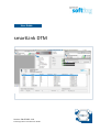
smartLink DTM
User Guide
Version: EN-052023-1.10

Softing Industrial Automation GmbH
Richard-Reitzner-Allee 6
85540 Haar / Germany
https://industrial.softing.com
Scan the QR code to find the latest documentation on the product web page under Downloads.
Disclaimer of liability
The information contained in these instructions corresponds to the technical status at the time of printing of it and is
passed on with the best of our knowledge. Softing does not warrant that this document is error free. The information in
these instructions is in no event a basis for warranty claims or contractual agreements concerning the described products,
and may especially not be deemed as warranty concerning the quality and durability pursuant to Sec. 443 German Civil Code.
We reserve the right to make any alterations or improvements to these instructions without prior notice. The actual design
of products may deviate from the information contained in the instructions if technical alterations and product
improvements so require.
Trademarks
FOUNDATION™ and HART® are registered marks of the FieldComm Group of Austin, Texas, USA.
OpenSource
To comply with international software licensing terms, we offer the source files of open source software used in our
products. For details see https://opensource.softing.com/
If you are interested in our source modifications and sources used, please contact: info@softing.com
https://industrial.softing.com/support/support-form
info.automation@softing.com
support.automation@softing.com
+ 49 89 4 56 56-340

Version EN-052023-1.10 3
Table of Contents
Table of Contents
Chapter 1 ...................................................................................... 5About this guide
............................................................................................................... 51.1 Read me first
............................................................................................................... 51.2 Target audience
............................................................................................................... 51.3 Typographic conventions
............................................................................................................... 61.4 Document history
............................................................................................................... 61.5 Related documentation and videos
............................................................................................................... 61.6 Document feedback
Chapter 2 ...................................................................................... 7About smartLink DTM
............................................................................................................... 72.1 Intended use
............................................................................................................... 72.2 Software and functionality
............................................................................................................... 82.3 What is a Field Device Tool
............................................................................................................... 82.4 What is a Device Type Manager
............................................................................................................... 102.5 What is a frame application
............................................................................................................... 102.6 HART
Chapter 3 ...................................................................................... 11Installing smartLink DTM
Chapter 4 ...................................................................................... 12smartLink DTM user interface explained
Chapter 5 ...................................................................................... 14Using smartLink DTM
............................................................................................................... 145.1 Starting FDT frame application
............................................................................................................... 165.2 Adding a smartLink HW-DP or smartLink SW-HT HART
............................................................................................................... 175.3 Setting connection parameters
............................................................................................................... 185.4 Connecting a smartLink node
............................................................................................................... 195.5 Setting the channel count
............................................................................................................... 215.6 Assigning a channel
.......................................................................................................... 21
smartLink HW-DP HART 5.6.1
.......................................................................................................... 24
smartLink SW-HT HART 5.6.2
............................................................................................................... 275.7 Connecting a HART field device
............................................................................................................... 285.8 Reading connected smartLink node
............................................................................................................... 325.9 Additional user interface menus
.......................................................................................................... 32
About smartLink DTM 5.9.1
.......................................................................................................... 33
Documentation of access parameters 5.9.2
.......................................................................................................... 34
Troubleshooting 5.9.3
.......................................................................................................... 35
Audit trail 5.9.4
Chapter 6 ...................................................................................... 37Troubleshooting

This page is intentionally left blank.
4 Version EN-052023-1.10

Chapter 1 - About this guide
Version EN-052023-1.10 5
1About this guide
1.1 Read me first
Please read this guide carefully before using the device to ensure safe and proper use. Softing does
not assume any liability for damages due to improper installation or operation of this product.
This document is not warranted to be error-free. The information contained in this document is
subject to change without prior notice. To obtain the most current version of this guide, visit the
product website.
1.2 Target audience
This guide is intended for experienced operation personnel and network specialists responsible for
configuring and maintaining field devices in process automation networks. Before installing and
operating the smartLink DTM make sure that you have read and fully understood the safety
requirements and working instructions in this guide.
1.3 Typographic conventions
The following conventions are used throughout Softing customer documentation:
Keys, buttons, menu items, commands and other
elements involving user interaction are set in bold
font and menu sequences are separated by an
arrow
Open Start Control Panel Programs
Buttons from the user interface are enclosed in
brackets and set to bold typeface
Press [Start] to start the application
Coding samples, file extracts and screen output is
set in Courier font type
MaxDlsapAddressSupported=23
Filenames and directories are written in italic
Device description files are located in C:
\<Application
name>\delivery\software\Device Description
files
CAUTION
CAUTION indicates a potentially hazardous situation which, if not avoided, may result in
damage or injury.
Note
This symbol is used to call attention to notable information that should be followed
during installation, use, or servicing of this device.
Hint
This symbol is used when providing you with helpful user hints.

smartLink DTM - User Guide
6Version EN-052023-1.10
1.4 Document history
Document version
Changes since last version
1.00
first version
1.10
DTM description for smartLink SW-HT added
1.5 Related documentation and videos
See the following links for additional and related product information:
smartLink HW-DP User Guide
smartLink SW-HT User Guide
1.6 Document feedback
We would like to encourage you to provide feedback and comments to help us improve the
documentation. You can write your comments and suggestions to the PDF file using the editing tool
in Adobe Reader and email your feedback to support.automation@softing.com.
If you prefer to write your feedback directly as an email, please include the following information
with your comments:
document name
document version (as shown on cover page)
page number

Chapter 2 - About smartLink DTM
Version EN-052023-1.10 7
2About smartLink DTM
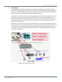
2.1 Intended use
The smartLink DTM tool is used to configure, diagnose and maintain HART field devices that are
connected to smartLink via Remote I/Os (RIOs). This chapter describes the application scenarios and
functionality of this tool including the relevant Field Device Tool (FDT) and HART technologies. Any
other use is deemed non-intended use.
2.2 Software and functionality
smartLink DTM takes over the entire protocol and device-specific management for communicating
with HART devices via the corresponding Softing smartLink.
Note
To grant smartLink unrestricted communication with HART devices, you must first
activate the optionally available licenses for smartLink and update its firmware to at
least version 1.10. For more information see the smartLink HW-DP and smartLink SW-HT
user guides.
Using the smartLink DTM you can parameterize and diagnose any number of HART devices. Please
note that suitable DeviceDTMs are required to parameterize the devices. These DeviceDTMs are
typically provided by the device manufacturer.
The smartLink DTM offers the following functionality:
Configuration of access parameters for individual smartLink devices.
Assignment of channels for the HART devices connected to the smartLink.
Access to HART devices via smartLink.
Selection of the Remote I/O module channels connecting to HART devices.
Internationalization (UTF8) and localization for English and German.
Control of access to critical functions according to the FDT user role concept.
Logging of audit trail events (must be supported by the FDT frame application).
Documentation of the smartLink access parameters.

smartLink DTM - User Guide
8Version EN-052023-1.10
2.3 What is a Field Device Tool
The Field Device Tool (FDT) is a standard communication protocol used in industrial automation to
communicate with field devices. FDT simplifies and saves time in the commissioning and
maintenance of increasingly complex installations which consist of a growing number of field
devices from different manufacturers. FDT is a standardized software interface for the configuration,
parameterization and handling of intelligent field devices, regardless of the manufacturer and
communication protocol. FDT is based on the existing fieldbus technologies and extends them by a
fieldbus-independent software interface between the devices and the engineering system. The
most diverse automation components from various manufacturers can thus be configured,
parameterized and managed using only one engineering system, independently of the protocols or
fieldbuses over which the devices communicate. To make the devices easy to commission and
handle, FDT defines a wide variety of graphical options for describing and operating the devices. FDT
offers different user roles and defines specific access rights, e.g. for maintenance, commissioning,
monitoring, etc.
2.4 What is a Device Type Manager
The central component of a Field Device Tool (FDT) is the Device Type Manager. Known as DTM, this
software component is supplied by a device manufacturer together with the device. It is somewhat
like a software driver for a specific printer. It contains all device-specific data, functions and
graphical controls. DTMs are used in industrial automation and process control systems to manage
communication and configuration of field devices such as sensors, actuators, controllers, and other
industrial devices. These devices typically communicate using protocols such as HART (Highway
Addressable Remote Transducer), FOUNDATION Fieldbus, PROFIBUS (Process Field Bus), or other
industrial communication protocols. A Device Type Manager provides the interface between the
field devices and the automation system, allowing for configuration, monitoring, and control of
these devices.
There are three types of DTMs:
DeviceDTM
The DeviceDTM is a DTM that represents a specific field device. It contains all the information
on configuration, diagnostics and documentation that is distinctive for the device. To make all
the desired functions of the device available in the engineering system, the DTM uses the
communication services of a CommDTM or GatewayDTM. A DeviceDTM is often simply called a
DTM. This should be avoided because the term DTM is a generic term for all kinds of DTMs.
CommDTM
The CommDTM (communication DTM) is a DTM that represents a communication device, such as
a PC interface board, which acts as a master on a fieldbus network. The CommDTM encapsulates
all communication-specific aspects, and manages and configures the communication module
(e.g. PC interface board).
To configure and test a device, the relevant DeviceDTM transmits communication requests as
XML documents via a COM interface to a communication channel of the CommDTM. A
communication channel represents the fieldbus access within a communication device. The
communication device may provide one or more communication channels.

Chapter 2 - About smartLink DTM
Version EN-052023-1.10 9
GatewayDTM
A GatewayDTM is a DTM that represents a physical gateway between two fieldbus segments.
The fieldbus segments typically differ in the protocol (e.g. HART/PROFIBUS) and/or the physical
properties. A GatewayDTM contains functionality that is specific to the bridged communication
protocols and to the manufacturer-dependent gateway properties.
To configure and test a field device on the target segment of the gateway (the segment behind
a gateway from the point of view of the fieldbus access), the relevant DeviceDTM transmits
communication requests as XML documents via a COM interface to a communication channel of
the GatewayDTM. A communication channel represents a path between fieldbus segments
within a physical gateway.
The gateway may provide one or more communication channels. The GatewayDTM transforms
the communication requests that are specific to the communication protocol used by the device
into communication requests according to the fieldbus access. It then passes them on to the
CommDTM. Communication across segment boundaries by using a GatewayDTM is referred to
as nested communication.
Fieldbus-independent FDT concept

smartLink DTM - User Guide
10 Version EN-052023-1.10
2.5 What is a frame application
An FDT (Field Device Tool) frame application is a software that provides a platform or framework for
configuring, managing, diagnosing, and monitoring field devices in industrial automation and control
systems. It allows you to import device information by accessing the relevant DTMs provided by the
device manufacturer. An FDT frame application is the only application within the FDT concept which
is implemented as an executable. It is application is responsible for loading and unloading the DTMs,
managing and saving data in a project database, managing a device catalog, generating a project
documentation, supervising user and access rights, and displaying all user interfaces of the DTMs.
There are a number of FDT frame applications on the market each offering a different user interface
structure and visualization. For the sake of consistency, this user guide describes the integration of
the smartLink DTM and connection the Softing smartLink instances using the frame application
PACTwareTM .
2.6 HART
HART (Highway Addressable Remote Transducer) is a two-way communication protocol designed for
field devices in process automation using a 4-20mA analog signal. HART provides digital
communication capabilities over the analog current loop by superimposing digital signals on top of
the analog signal. It can be used to parameterise, diagnose and poll process values.
The HART protocol implements OSI layers 1 (physical layer), 2 (data link layer) and 7 (application
layer). The HART Physical Layer defines the electrical connection between HART devices, typically on
twisted copper cables which transmit the 4-20mA analog signal of the device. For transmitting the
HART bit stream a high frequency signal is superimposed on the analog signal is using the Continuous
Phase Frequency Shift Keying (CPFSK) principle where the bit values of 0 and 1 are represented by
different frequencies without causing phase jumps during frequency switching. The data
transmission rate is 1200 bps. To synchronize transmitter and receiver preambles are added to the
Physical Layer.
The Data Link Layer deals mostly with the structure of the data packets, device addressing, error
correction and bus access control. Insofar, HART is a binary byte-oriented master-slave protocol on
which bus access is organized by the token-passing method. Device addressing is done either by
using a polling address that can be individually assigned to a slave (field device) or by a specific bit
address which is a unique identifier permanently set by the device manufacturer. With HART you can
have to masters.
The primary master is normally the control system master while the secondary master is used only
when required, typically by a temporarily connected hand-held communicator such as the smartLink
device. The token-passing protocol communicates between both masters to control the bus access.
During normal operation the slaves do not have an active role. They may, however, be used in what
is called burst mode communication, a method where the slaves are instructed to continuous burst
(broadcast) messages, thereby taking part in the token-passing communication.
The Application Layer handles through a serious of HART commands the generation (master) and
processing (slave) of data packets. The HART commands are divided into three categories: The
Universal Commands which must be supported by all slaves. The Common Practice Commands which
even optional device manufacturers are encouraged to prioritize them over Device-Specific
Commands. The Device-Specific Commands which include only device functions implemented by
specific manufacturers.

Chapter 3 - Installing smartLink DTM
Version EN-052023-1.10 11
3Installing smartLink DTM
Before you can work with your smartLink you have to install the smartLink DTM. Download the
smartLink DTM application from the Download Center or the smartLink HW-DP product page.
1. Download the latest version of the smartLink DTM.
2. Double-click the setup.exe file to start the installation.
3. Select the installation language.
4. Follow the install wizard instructions.

smartLink DTM - User Guide
12 Version EN-052023-1.10
4smartLink DTM user interface explained
The user interface of Softing smartLink DTM follows the basic design according to the FDT style
guide. The Chapter gives you a general overview of the smartLink DTM user interface, its windows
and functions in the FDT frame application PACTware.
Note
For a details on how to connect and configure Softing smartLink HW-DP and smartLink
SW-HT nodes and parameterizing HART RIOs see the next chapter Using smartLink
DTM .
The informations area shows an image of a smartLink, the corporate logo and the names of the
product, the device and the vendor.
The application area shows the operational elements for the tasks that are performed in a user
interface.
The action area contains buttons to execute the main actions.
The status area shows general status information about smartLink HART.
The optional navigation area described in the FDT style guide is not included in the smartLink DTM
user interface.
Status symbols
Field 1 of the status area displays the following DTM status symbols:
The smartLink device is disconnected.
A connection has been established to smartLink and it is inactive. This state occurs only briefly
when smartLink DTM is connected and disconnected. When smartLink DTM is connected it
changes to an active connection right away. This state does not occur during normal operation.
14

Chapter 4 - smartLink DTM user interface explained
Version EN-052023-1.10 13
A connection has been established to smartLink and it is active.
A connection to the smartLink changes from inactive to active.
A connection to the smartLink changes from active to inactive.
A smartLink connection has been disrupted.
Field 2 of the status area shows the following communication states:
smartLink is currently not communicating.
smartLink is currently communicating.
Field 3 typically shows the processing state of the instance dataset of the device dataset while field
4 shows if the instance dataset has been modified compare with the device dataset. Both fields are
always empty, because smartLink HART does not have any device parameters.
Field 5 area shows the input state as follows:
The current input values are unchanged and valid.
The current input values have been modified.
The current input values are invalid.
Field 6 is always empty. It normally shows if the user interface operates in block mode or in direct
mode. The smartLink DTM user interface always runs in block mode and this filed has to be empty
according to the FDT style guide.

smartLink DTM - User Guide
14 Version EN-052023-1.10
5Using smartLink DTM
In this chapter you will learn how to work with smartLink DTM and read DeviceDTMs in an FDT frame
application.
5.1 Starting FDT frame application
Like any DTM, smartLink DTM must be loaded into an FDT frame application. The services provided by
smartLink DTM for communication with HART devices can be used to read DeviceDTMs running in the
same FDT frame application.
The FDT frame applications of different manufacturers prioritize different tasks and objectives.
Therefore, the design of the user interface, the functionality provided and the operation may also
vary significantly from frame application to frame application. The following sections describes the
PACTwareTM frame application. If you are using a different frame application, consult the related
user manual.
1. Select Windows Start PACTware 4.1 PACTware 4.1 to start the FDT frame application (in
this case PACTware).
With many frame applications you need to log on with your user name and password after
initial startup. You may also have to create a new project before you can start adding DTMs.
Note
The local DTM device catalog is typically updated automatically. If however for
whatever reason this is not done automatically you will need to update the device
catalog manually.
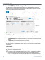
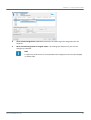
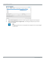
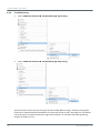
2. Select Device catalog Update device catalog to update the local device DTM to include the
smartLink DTM (provided this is not done automatically).
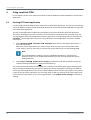
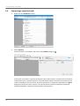
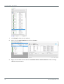
The screenshot below shows the PACTware user interface immediately after startup displaying the
device catalog. Remember that you have to update the device catalog after installing new DTMs to
inform the frame application of the newly installed DTMs and the devices they support. This process
is specific for the frame application you are using. Refer to the user manual of the frame application
for the relevant information. If you are using PACTware, click [Update device catalog] in the device
catalog.

Chapter 5 - Using smartLink DTM
Version EN-052023-1.10 15
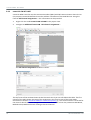
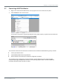
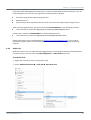
On the left side of the PACTware window you see the project view, which currently contains only the
root node of the project. Devices are typically represented in a hierarchical tree structure in the
project view of a frame application. The common root of all devices is often a node that represents
the overall project instead of a device. The communication devices are shown as child nodes of this
root. The field devices are represented as the leaves of the tree. There may be gateways connected
between a communication device and field devices.
On the right side of the PACTware window you see the devices that are supported by the installed
DTMs. In screenshot above you find various manufacturer listed in the device catalog.
In the next section you will learn how to add a communication DTM for a smartLink to the project.

smartLink DTM - User Guide
16 Version EN-052023-1.10
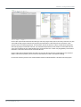
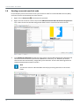
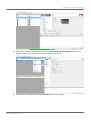
5.2 Adding a smartLink HW-DP or smartLink SW-HT HART
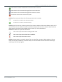
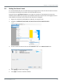
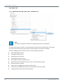
1. Right-click the HOST PC bar in the project view to open the context menu.
2. Select Add device from the menu.
3. Select a smartLink (HW-DP or SW-HT)from the All Devices list.
4. Click [OK] to add the device to a project.
The selected smartLink node (HW-DP or SW-HT) appears underneath the Host PC bar. At this
point, the online state is disconnected ( ).

Chapter 5 - Using smartLink DTM
Version EN-052023-1.10 17
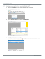
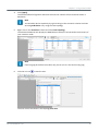
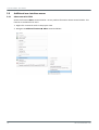
5.3 Setting connection parameters
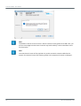
To connect to the smartLink device you must provide an IP address and login credentials. For the
HART IP communication you will additionally need to enter a port number on which the smartLink
HART IP server is running.
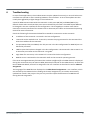
1. Right-click the node smartLink instance in the project view.
2. Select Parameter from the menu.
3. Enter the IP address of the smartLink device, the port number of the IP server, as well as the
user name and password of the account to your smartLink.
4. Click [Apply] to confirm the change.
5. Click [OK] to close the interface window
Note
The login password is encrypted and not shown in clear text. The HART IP port must have
the same configuration as the smartLink port.

smartLink DTM - User Guide
18 Version EN-052023-1.10
5.4 Connecting a smartLink node
1. Right-click the smartLink instance.
2. Select Connect.
If the connection is successful, the online state symbol change to .
A successful connection is typically displayed in the project view by a symbol next to smartLink.
In PACTware this is a closed connector. In the FDT status model a successful connection can be
inactive (standby) or active (online). An active connection is displayed in PACTware by a green
background of the connector symbol. A connection which has been successfully created by
smartLink DTM with smartLink is always shown as being active.

Chapter 5 - Using smartLink DTM
Version EN-052023-1.10 19
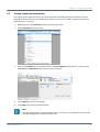
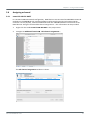
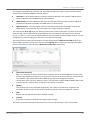
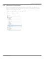
5.5 Setting the channel count
It is recommended that you set a sufficiently high enough channel count for each smartLink instance
in the project according to the number of connected HART devices.
Using the function Set channel count you can assign any number of 1 to 99 channels to the next
smartLink that is added to the project. If you decide to leave the channel count unchanged, the next
node added to the project will by default have 100 channels assigned.
1. Right-click a smartLink node (HW-DP or SW-HT) in the project view.
2. Navigate to Additional functions Set channel count of new smartLink nodes...
3. Set the number of channels for the new smartLink node in the Channel count field.
4. Click [Apply] to confirm the change.
5. Click [OK] to close the interface window.

smartLink DTM - User Guide
20 Version EN-052023-1.10
Note
The default value for channel count is 100. If a channel count greater than 500 is set, you
will see a message box that more channels may lead to delays. Use a reasonable count
for the project.
Note
The new channel count will be applied only to the smartLink instance added to the
project. The channel count of all existing nodes in the project will remain unchanged.
La page charge ...
La page charge ...
La page charge ...
La page charge ...
La page charge ...
La page charge ...
La page charge ...
La page charge ...
La page charge ...
La page charge ...
La page charge ...
La page charge ...
La page charge ...
La page charge ...
La page charge ...
La page charge ...
La page charge ...
La page charge ...
-
 1
1
-
 2
2
-
 3
3
-
 4
4
-
 5
5
-
 6
6
-
 7
7
-
 8
8
-
 9
9
-
 10
10
-
 11
11
-
 12
12
-
 13
13
-
 14
14
-
 15
15
-
 16
16
-
 17
17
-
 18
18
-
 19
19
-
 20
20
-
 21
21
-
 22
22
-
 23
23
-
 24
24
-
 25
25
-
 26
26
-
 27
27
-
 28
28
-
 29
29
-
 30
30
-
 31
31
-
 32
32
-
 33
33
-
 34
34
-
 35
35
-
 36
36
-
 37
37
-
 38
38


