Installation/Connections
Installation/Anschluß
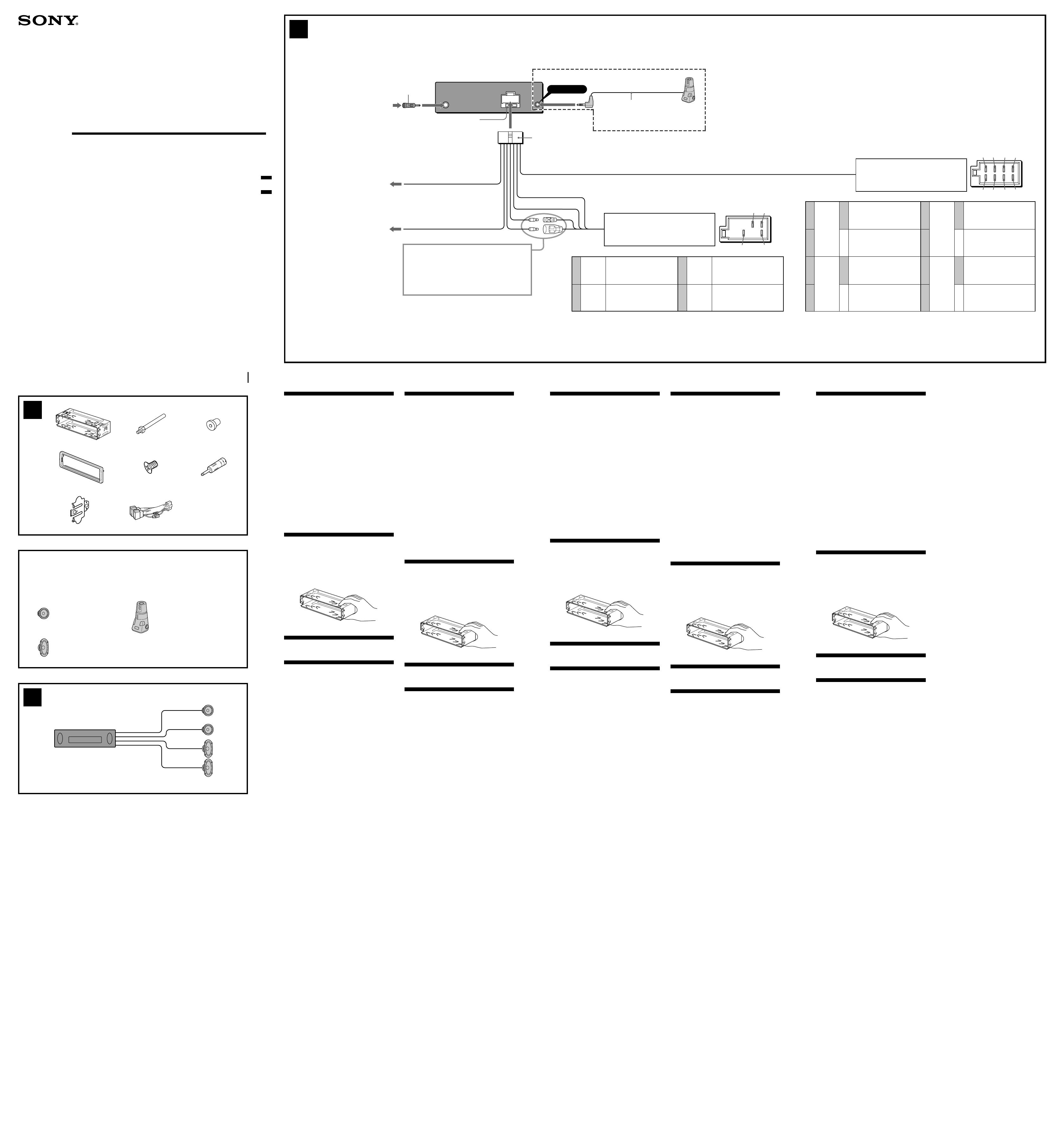
Installation/Connexions
Installazione/Collegamenti
Montage/Aansluitingen
FM/MW/LW
Compact Disc
Player
CDX-L360
CDX-L350
Sony Corporation © 2001 Printed in Thailand
3-227-372-11 (1)
Equipment used in illustrations (not supplied)
In Abbildungen dargestellte Geräte (nicht mitgeliefert)
Appareils utilisés dans les illustrations (non fournis)
Apparecchiatura utilizzata nelle illustrazioni (non in dotazione)
Apparatuur gebruikt voor illustratiedoeleinden (niet meegeleverd)
Rear speaker
Hecklautsprecher
Haut-parleur arrière
Diffusori posteriori
Achterluidspreker
Front speaker
Frontlautsprecher
Haut-parleur avant
Diffusori anteriori
Voorluidspreker
Rotary commander RM-X4S
(CDX-L360 only)
Joystick RM-X4S
(Nur CDX-L360)
Satellite de commande RM-X4S
(CDX-L360 seulement)
Telecomando a rotazione RM-X4S
(Solo CDX-L360)
Bedieningssatelliet RM-X4S
(Alleen voor de CDX-L360)
2
Cautions
•This unit is designed for negative earth 12 V DC
operation only.
•Do not get the wires under a screw, or caught in
moving parts (e.g. seat railing).
•Before making connections, turn the car ignition
off to avoid short circuits.
•Connect the power connecting cord 8 to the unit
and speakers before connecting it to the auxiliary
power connector.
•Run all earth wires to a common earth point.
•Be sure to insulate any loose unconnected wires
with electrical tape for safety.
Notes on the power supply cord (yellow)
•When connecting this unit in combination with
other stereo components, the connected car
circuit’s rating must be higher than the sum of
each component’s fuse.
•When no car circuits are rated high enough,
connect the unit directly to the battery.
Parts list (1)
The numbers in the list are keyed to those in the
instructions.
Cautions
Handle the bracket 1 carefully to avoid injuring
your fingers.
Connection example (2)
Connection diagram (3)
Warning
If you have a power aerial without a relay box,
connecting this unit with the supplied power
connecting cord 8 may damage the aerial.
Notes on the control leads
• The power aerial control lead (blue) supplies +12 V
DC when you turn on the tuner or when you
activate the AF (Alternative Frequency), TA (Traffic
Announcement) function.
• When your car has built-in FM/MW/LW aerial in
the rear/side glass, connect the power aerial
control lead (blue) or the accessory power input
lead (red) to the power terminal of the existing
aerial booster. For details, consult your dealer.
• A power aerial without a relay box cannot be used
with this unit.
Memory hold connection
When the yellow power input lead is connected,
power will always be supplied to the memory circuit
even when the ignition switch is turned off.
Notes on speaker connection
• Before connecting the speakers, turn the unit off.
• Use speakers with an impedance of 4 to 8 ohms,
and with adequate power handling capacities to
avoid its damage.
• Do not connect the speaker terminals to the car
chassis, or connect the terminals of the right
speakers with those of the left speaker.
• Do not connect the ground lead of this unit to the
negative (-) terminal of the speaker.
• Do not attempt to connect the speakers in parallel.
• Connect only passive speakers. Connecting active
speakers (with built-in amplifiers) to the speaker
terminals may damage the unit.
Précautions
•Cet appareil est conçu pour fonctionner sur
courant continu de 12 V avec masse négative.
•Evitez de fixer des vis sur les câbles ou de coincer
ceux-ci dans des pièces mobiles (par exemple,
armature de siège).
•Avant d’effectuer des raccordements, éteignez le
moteur pour éviter les courts-circuits.
•Brancher le cordon d’alimention 8 sur l’appareil
et les haut-parleurs avant de le brancher sur le
connecteur d’alimentation auxiliaire.
•Rassembler tous les fils de terre en un point de
masse commun.
•Veillez à isoler tout fil ou câble non connectés
avec du chatterton approprié.
Notes sur le cordon d’alimentation (jaune)
•Lorsque cet appareil est raccordé à d’autres
éléments stéréo, la valeur nominale des circuits de
la voiture raccordée doit être supérieure à la
somme des fusibles de chaque élément.
•Si aucun circuit de la voiture n’est assez puissant,
raccordez directement l’appareil à la batterie.
Liste des composants (1)
Les numéros de l’illustration correspondent à ceux
des instructions.
Avertissements
Manipulez précautionneusement le support 1
pour éviter de vous blesser aux doigts.
Exemple de raccordement (2)
Schémas de connexion (3)
Avertissement
Si vous disposez d’une antenne électrique sans
boîtier de relais, le branchement de cet appareil au
moyen du cordon d’alimentation fourni 8 risque
d’endommager l’antenne.
Remarques sur les fils de contrôle
• La sortie de commande de l’antenne (bleu) fournit
du courant continu de +12 V lorsque vous allumez
le sélecteur de canaux ou lorsque vous activez la
fonction TA (informations circulation) en AF
(fréquence alternative).
• Lorsque votre voiture est équipée d’une antenne
FM/MW/LW intégrée dans la vitre arrière/latérale,
raccordez la sortie de commande de l’antenne
(bleu) ou l’entrée d’alimentation des accessoires
(rouge) au bornier de l’amplificateur d’antenne
existant. Pour plus de détails, consultez votre
revendeur.
• Une antenne électrique sans boitier de relais ne
peut pas être utilisée avec cet appareil.
Connexion pour la conservation de la mémoire
Lorsque le fil d’entrée d’alimentation jaune est
connecté, le circuit de la mémoire est alimenté en
permanence même si la clé de contact est sur la
position d’arrêt.
Remarques sur la connexion des haut-parleurs
• Avant de raccorder les haut-parleurs, mettre
l’appareil hors tension.
• Utiliser des haut-parleurs ayant une impédance de
4 à 8 ohms et une capacité adéquate sous peine de
les endommager.
• Ne pas raccorder les bornes du système de haut-
parleurs au châssis de la voiture et ne pas
connecter les bornes du haut-parleur droit à celles
du haut-parleur gauche.
• Ne raccordez pas le câble de masse de cet appareil
à la borne négative (-) de l'enceinte.
• Ne pas tenter de raccorder les haut-parleurs en
parallèle.
• Ne pas connecter d’enceintes acoustiques actives
(avec amplificateurs intégrés) aux bornes
d’enceinte de cet appareil, pour éviter
d’endommager les enceintes. Veiller à raccorder
des enceintes passives.
Vorsicht
•Dieses Gerät ist ausschließlich für den Betrieb bei
12 V Gleichstrom (negative Erdung) bestimmt.
•Achten Sie darauf, daß die Kabel nicht unter einer
Schraube oder zwischen beweglichen Teilen wie
z. B. in einer Sitzschiene eingeklemmt werden.
•Schalten Sie, bevor Sie irgendwelche Anschlüsse
vornehmen, die Zündung des Fahrzeugs aus, um
Kurzschlüsse zu vermeiden.
•Verbinden Sie das Stromversorgungskabel 8 mit
dem Gerät und den Lautsprechern, bevor Sie es mit
dem Hilfsstromanschluß verbinden.
•Schließen Sie alle Erdungskabel an einen
gemeinsamen Massepunkt an.
•Aus Sicherheitsgründen müssen alle losen, nicht
angeschlossenen Drähte mit Isolierband abisoliert
werden.
Hinweise zum Stromversorgungskabel (gelb)
•Wenn Sie dieses Gerät zusammen mit anderen
Stereokomponenten anschließen, muß der
Autostromkreis, an den die Geräte angeschlossen
sind, eine höhere Leistung aufweisen als die
Summe der Sicherungen der einzelnen
Komponenten.
•Wenn kein Autostromkreis eine so hohe Leistung
aufweist, schließen Sie das Gerät direkt an die
Batterie an.
Teileliste (1)
Die Nummern in der Liste sind dieselben wie im
Erläuterungstext.
Sicherheitshinweise
Seien Sie beim Umgang mit der Halterung 1
vorsichtig, damit Sie sich nicht die Hände verletzen.
Anschlußbeispiel (2)
Anschlußdiagramm (3)
Warnung
Wenn Sie eine Motorantenne ohne Relaiskästchen
verwenden, kann durch Anschließen dieses Geräts
mit dem mitgelieferten Stromversorgungskabel 8
die Antenne beschädigt werden.
Hinweise zu den Steuerleitungen
• Die Motorantennen-Steuerleitung (blau) liefert + 12 V
Gleichstrom, wenn Sie den Tuner einschalten oder die
AF- (Alternativfrequenzsuche) oder die TA-Funktion
(Verkehrsdurchsagen) aktivieren.
• Wenn das Fahrzeug mit einer in der Heck-/
Seitenfensterscheibe integrierten FM (UKW)/MW/
LW-Antenne ausgestattet ist, schließen Sie die
Motorantennen-Steuerleitung (blau) oder die
Zubehörstromversorgungsleitung (rot) an den
Stromversorgungsanschluß des vorhandenen
Antennenverstärkers an. Näheres dazu erfahren
Sie bei Ihrem Händler.
• Es kann nur eine Motorantenne mit Relaiskästchen
angeschlossen werden.
Stromversorgung des Speichers
Wenn das gelbe Stromversorgungskabel angeschlossen
ist, wird der Speicher stets (auch bei ausgeschalteter
Zündung) mit Strom versorgt.
Hinweise zum Lautsprecheranschluß
• Schalten Sie das Gerät aus, bevor Sie die
Lautsprecher anschließen.
• Verwenden Sie Lautsprecher mit einer Impedanz
zwischen 4 und 8 Ohm und ausreichender
Belastbarkeit. Ansonsten können die Lautsprecher
beschädigt werden.
• Verbinden Sie die Lautsprecheranschlüsse nicht mit
dem Wagenchassis, und verbinden Sie auch nicht
die Anschlüsse des rechten mit denen des linken
Lautsprechers.
• Verbinden Sie die Masseleitung dieses Geräts nicht
mit dem negativen (-) Lautsprecheranschlufl.
• Versuchen Sie nicht, Lautsprecher parallel
anzuschließen.
• An die Lautsprecheranschlüsse dieses Geräts
dürfen nur Passivlautsprecher angeschlossen
werden. Schließen Sie keine Aktivlautsprecher
(Lautsprecher mit eingebauten Verstärkern) an, da
diese sonst beschädigt werden können.
Let op!
•Dit apparaat is ontworpen voor gebruik op
gelijkstroom van een 12 Volts auto-accu, negatief
geaard.
•Zorg ervoor dat de draden niet onder een schroef
of tussen bewegende onderdelen (b.v. zetelrail)
terechtkomen.
•Alvorens aansluitingen te verrichten moet u het
contact afzetten om kortsluiting te vermijden.
•Sluit het netsnoer 8 aan op het toestel en de
luidsprekers vooraleer u het op de
hulpvoedingsaansluiting aansluit.
•Sluit alle aarddraden op een gemeenschappelijk
aardpunt aan.
•Voorzie niet aangesloten draden om
veiligheidsredenen altijd van isolatietape.
Opmerkingen bij de voedingskabel (geel)
•Wanneer u dit toestel aansluit samen met andere
componenten, moet het vermogen van de
aangesloten autostroomkring groter zijn dan de som
van de de zekeringen van elke component
afzonderlijk.
•Wanneer het vermogen ontoereikend is, moet u
het toestel rechtstreeks aansluiten op de batterij.
Onderdelenlijst (1)
De nummers in de afbeelding verwijzen naar die in
de montage-aanwijzingen.
Opgelet
Houd de beugel 1 voorzichtig vast zodat u uw
vingers niet verwondt.
Voorbeeldaansluitingen (2)
Aansluitschema (3)
Opgelet
Indien u een elektrische antenne heeft zonder
relaiskast, kan het aansluiten van deze eenheid met
het bijgeleverde netsnoer 8 de antenne
beschadigen.
Opmerking betreffende de aansluitsnoeren
• De antennevoedingskabel (blauw) levert +12 V
gelijkstroom wanneer u de tuner aanschakelt of de
AF (Alternative Frequency), TA (Traffic
Announcement) functie activeert.
• Wanneer uw auto is uitgerust met een FM/MW/
LW-antenne in de achterruit/voorruit, moet u de
antennevoedingskabel (blauw) of de
hulpvoedingskabel (rood) aansluiten op de
voedingsingang van de bestaande
antenneversterker. Raadpleeg uw dealer voor
meer details.
• Met dit apparaat is het niet mogelijk een
automatische antenne zonder relaishuis te
gebruiken.
Instandhouden van het geheugen
Zolang de gele stroomdraad is aangesloten, blijft de
stroomvoorziening van het geheugen intact, ook
wanneer het contact van de auto wordt
uitgeschakeld.
Opmerkingen betreffende het aansluiten van de
luidsprekers
• Zorg dat het apparaat is uitgeschakeld, alvorens de
luidsprekers aan te sluiten.
• Gebruik luidsprekers met een impedantie van 4 tot
8 Ohm en let op dat die het vermogen van de
versterker kunnen verwerken. Als dit wordt
verzuimd, kunnen de luidsprekers ernstig
beschadigd raken.
• Verbind in geen geval de aansluitingen van de
luidsprekers met het chassis van de auto en sluit de
aansluitingen van de rechter en linker luidspreker
niet op elkaar aan.
• Verbind de massakabel van dit toestel niet met de
negatieve (-) aansluiting van de luidspreker.
• Probeer nooit de luidsprekers parallel aan te
sluiten.
• Sluit geen actieve luidsprekers (met ingebouwde
versterkers) aan op de luidspreker-aansluiting van
dit apparaat. Dit zal leiden tot beschadiging van
de actieve luidsprekers. Sluit dus altijd uitsluitend
luidsprekers zonder ingebouwde versterker aan.
Attenzione
•Questo apparecchio è stato progettato per l’uso
solo a 12 V CC con massa negativa.
•Evitare che i cavi rimangano bloccati da una vite o
incastrati nelle parti mobili (ad esempio nelle
guide scorrevoli dei sedili).
•Prima di effettuare i collegamenti, spegnere il
motore dell’automobile onde evitare di causare
cortocircuiti.
•Collegare il cavo di collegamento
dell’alimentazione 8 all’apparecchio e ai
diffusori prima di collegarlo al connettore di
alimentazione ausiliare.
•Portare tutti i cavi di massa a un punto di
massa comune.
•Per sicurezza, assicurarsi di isolare qualsiasi
cavo non collegato mediante apposito nastro.
Note sul cavo di alimentazione (giallo)
•Se questo apparecchio viene collegato in
combinazione con altri componenti stereo, la
potenza nominale dei circuiti dell’automobile
deve essere superiore a quella prodotta dalla
somma dei fusibili di ciascun componente.
•Se la potenza nominale dei circuiti
dell’automobile non è sufficiente, collegare
l’apparecchio direttamente alla batteria.
Elenco dei componenti (1)
I numeri nella lista corrispondono a quelli riportati
nelle istruzioni.
Attenzione
Maneggiare la staffa 1 con cautela per evitare di
ferirsi le mani.
Esempi di collegamento (2)
Schema di collegamento (3)
Avvertenza
Quando si collega l’apparecchio con il cavo di
alimentazione in dotazione 8, si potrebbe
danneggiare l’antenna elettrica se questa non ha la
scatola di relè.
Note sui cavi di controllo
• Il cavo (blu) di controllo dell’antenna elettrica
fornisce alimentazione pari a +12 V CC quando si
attiva il sintonizzatore o la funzione TA (notiziario
sul traffico) AF (frequenza alternativa).
• Se l’automobile è dotata di antenna FM/MW/LW
incorporata nel vetro posteriore/laterale, collegare il
cavo (blu) di controllo dell’antenna elettrica o il cavo
(rosso) di ingresso dell’alimentazione opzionale al
terminale di alimentazione del preamplificatore
dell’antenna esistente. Per ulteriori informazioni,
consultare il proprio fornitore.
• Non è possibile usare un’antenna elettrica senza
scatola a relè con questo apparecchio.
Collegamento per la conservazione della memoria
Quando il cavo di ingresso alimentazione giallo è
collegato, viene sempre fornita alimentazione al
circuito di memoria anche quando la chiavetta a
accensione è spenta.
Note sul collegamento dei diffusori
• Prima di collegare i diffusori spegnere
l’apparecchio.
• Usare diffusori di impedenza compresa tra 4 e 8
ohm e con capacità di potenza adeguata,
altrimenti i diffusori potrebbero venir danneggiati.
• Non collegare i terminali del sistema diffusori al
telaio dell’auto e non collegare i terminali del
diffusore destro a quelli del diffusore sinistro.
• Non collegare il cavo di terra di questo
apparecchio al terminale negativo (-) del diffusore.
• Non collegare i diffusori in parallelo.
• Non collegare alcun diffusore attivo (con
amplificatore incorporato) ai terminali dei diffusori
dell’apparecchio perché si potrebbero danneggiare
i diffusori attivi. Assicurarsi di collegare diffusori
passivi a questi terminali.
Yellow
Gelb
Jaune
Giallo
Geel
Blue
Blau
Bleu
Blu
Blauw
continuous power supply
permanente Stromversorgung
alimentation continue
alimentazione continua
continu voeding
power aerial control
Motorantenne
antenne électrique
comando dell’antenna elettrica
automatische antenne
7
8
4
5
Red
Rot
Rouge
Rosso
Rood
Black
Schwarz
Noir
Nero
Zwart
switched power supply
geschaltete Stromversorgung
alimentation commutée
alimentazione commutata
geschakelde voeding
earth
Masse
masse
terra
aarding
Positions 1, 2, 3 and 6 do not have pins.
An Position 1, 2, 3 und 6 befinden sich keine Stifte.
Les positions 1, 2, 3 et 6 ne comportent pas de broches.
Le posizioni 1, 2, 3 e 6 non hanno piedini.
De posities 1, 2, 3 en 6 hebben geen pins.
6
from car aerial*
1
von Autoantenne*
1
de l’antenne de la voiture*
1
dall’antenna dell’auto*
1
van een auto-antenne*
1
Fuse (10 A)
Sicherung (10 A)
Fusible (10 A)
Fusibile (10 A)
Zekering (10 A)
8
Insert with the cord upwards.
Mit dem Kabel nach oben einsetzen!
Insérez avec le câble vers le haut.
Inserire con il cavo rivolto verso l’alto.
Inbrengen met het snoer naar boven.
REMOTE IN
AMP REM
not used
Nicht verwendet
Non utilisé
Non utilizzato
Vrij
Light blue
Hellblau
Bleu ciel
Azzurro
Hemelsblauw
Blue/white striped
Blau-weiß gestreift
Rayé bleu/blanc
A strisce blu e bianche
Blauw/wit gestreept
1
2
3
4
Speaker, Rear, Right
Lautsprecher hinten rechts
haut-parleur, arrière, droit
Diffusore, posteriore, destro
Luidspreker, achter, rechts
Speaker, Rear, Right
Lautsprecher hinten rechts
haut-parleur, arrière, droit
Diffusore, posteriore, destro
Luidspreker, achter, rechts
Speaker, Front, Right
Lautsprecher vorne rechts
haut-parleur, avant, droit
Diffusore, anteriore, destro
Luidspreker, voor, rechts
Speaker, Front, Right
Lautsprecher vorne rechts
haut-parleur, avant, droit
Diffusore, anteriore, destro
Luidspreker, voor, rechts
5
6
7
8
Speaker, Front, Left
Lautsprecher vorne links
haut-parleur, avant, gauche
Diffusore, anteriore, sinistro
Luidspreker, voor, links
Speaker, Front, Left
Lautsprecher vorne links
haut-parleur, avant, gauche
Diffusore, anteriore, sinistro
Luidspreker, voor, links
Speaker, Rear, Left
Lautsprecher hinten links
haut-parleur, arrière, gauche
Diffusore, posteriore, sinistro
Luidspreker, achter, links
Speaker, Rear, Left
Lautsprecher hinten links
haut-parleur, arrière, gauche
Diffusore, posteriore, sinistro
Luidspreker, achter, links
Purple
Violett
Mauve
Viola
Paars
White
Weiß
Blanc
Bianco
Wit
Grey
Grau
Gris
Grigio
Grijs
+
–
+
–
+
–
+
–
from the car’s speaker connector
vom Lautsprecheranschluß des Fahrzeugs
du connecteur de haut-parleur de la voiture
dal connettore del diffusore dell’auto
van de autoluidsprekerstekker
from the car’s power connector
vom Stromanschluß des Fahrzeugs
du connecteur d’alimentation de la voiture
dal connettore di alimentazione dell’auto
van de autovoedingsstekker
ATT
See “Power connection diagram” in the back for details.
Näheres dazu finden Sie im „Stromanschlußdiagramm”.
Blättern Sie dazu bitte um.
Voir le “
Schéma de connexion d’alimentation
” au verso
pour plus de détails.
Per ulteriori informazioni, vedere “Diagramma dei
collegamenti di alimentazione” che si trova sul retro.
Zie “Voedingsaansluitschema” op de schterkant voor
meer details.
to the interface cable of a car telephone
an Schnittstellenkabel eines Autotelefons
vers le cordon de liaison d’un téléphone de
voiture
al cavo interfaccia di un telefono per auto
naar het interface-snoer van een
autotelefoon
3
*
1
Note for the aerial connecting
If your car aerial is an ISO (International
Organisation for Standardisation) type,
use the supplied adaptor 6 to connect
it.
First connect the car aerial to the
supplied adaptor, then connect it to the
aerial jack of the master unit.
*
2
CDX-L360 only
*
1
Hinweis zum Anschließen der Antenne
Wenn Ihre Fahrzeugantenne der
ISO-Norm (ISO = International
Organization for Standardization -
Internationale Normungsgemeinschaft)
entspricht, schließen Sie sie mit Hilfe des
mitgelieferten Adapters 6 an.
Verbinden Sie zuerst die
Fahrzeugantenne mit dem
mitgelieferten Adapter, und verbinden
Sie diesen dann mit der
Antennenbuchse des Hauptgeräts.
*
2
Nur CDX-L360
*
1
Remarque sur le raccordement de
l’antenne
Si votre antenne de voiture est de type
ISO (organisation internationale de
normalisation), utilisez l’adaptateur
fourni 6 pour la raccorder.
Raccordez d’abord l’antenne de voiture
à l’adaptateur fourni et, ensuite, à la
prise d’antenne de l’appareil principal.
*
2
CDX-L360 seulement
*
1
Nota per il collegamento dell’antenna
Se la vostra antenna della macchina è di
tipo ISO (International Organization
Standardization), utilizzare l’adattatore
6 in dotazione per collegarla.
Collegare prima l’antenna della
macchina all’adattatore in dotazione,
quindi collegarla alla presa dell’antenna
dell’apparecchio principale.
*
2
Solo CDX-L360
*
1
Opmerking bij de antenne-aansluiting
Indien uw wagen is uitgerust met een
antenne van het type ISO (International
Organisation for Standardization), moet
u die aansluiten met behulp van de
meegeleverde adaptor 6.
Sluit eerst de auto-antenne aan op de
meegeleverde adaptor en vervolgens de
antennestekker op het hoofdtoestel.
*
2
Alleen voor de CDX-L360
*
2
1 3
4
2
6
8
1
× 2
5
× 2
7
Negative polarity positions 2, 4, 6, and 8 have striped cords.
An den negativ gepolten Positionen 2, 4, 6 und 8 befinden sich gestreifte Adern.
Les positions de polarité négative 2, 4, 6 et 8 sont dotées de cordons rayés.
Le posizioni a polarità negativa 2, 4, 6 e 8 hanno cavi rigati.
De negatieve posities 2, 4, 6 en 8 hebben gestreepte kabels.
Green
Grün
Vert
Verde
Groen

