
Guide d'installation
Installation Instructions
Manual de instalación
Slide-in Electric Ranges with European Convection
fr Cuisinières électriques à encastrer
es Estufas eléctricas empotrables

Table of Contents
Questions?
1-800-944-2904
www.boschappliances.com
5551 McFadden Ave.
Huntington Beach, CA 92649
We look forward to hearing from you!
Safety . . . . . . . . . . . . . . . . . . . . . . . . . . . . . . . . . . . . . . . . . . . . . . . . . . . . . 1
Installation . . . . . . . . . . . . . . . . . . . . . . . . . . . . . . . . . . . . . . . . . . . . . . . . . 2
Before You Begin . . . . . . . . . . . . . . . . . . . . . . . . . . . . . . . . . . . . . . . . . . . . . . . . . . . . . . . . . . . . . 2
Installation Procedure . . . . . . . . . . . . . . . . . . . . . . . . . . . . . . . . . . . . . . . . . . . . . . . . . . . . . . . . . . 7
Service . . . . . . . . . . . . . . . . . . . . . . . . . . . . . . . . . . . . . . . . . . . . . . . . . . . 15
Before Calling Service . . . . . . . . . . . . . . . . . . . . . . . . . . . . . . . . . . . . . . . . . . . . . . . . . . . . . . . . . 15

English 1
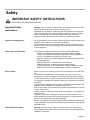
IMPORTANT SAFETY INSTRUCTIONS
READ AND SAVE THESE INSTRUCTIONS
Important Safety
Instructions
• Warning: If the information in this manual is not followed exactly, fire or shock
may result causing property damage or personal injury.
• WARNING: Do not repair or replace any part of the appliance unless specifi-
cally recommended in the manuals. Improper installation, service or mainte-
nance can cause injury or property damage. Refer to this manual for
guidance. All other servicing should be done by a qualified technician.
Appliance Handling Safety • Do not lift appliance by door handle. Remove the door for easier handling and
installation. See instructions in Use and Care Manual.
• Unit is heavy and requires at least two people or proper equipment to move.
• Hidden surfaces may have sharp edges. Use caution when reaching behind
or under appliance.
Safety Codes and Standards • This appliance complies with one or more of the following Standards:
UL 858, The Standard for the Safety of Household Electric Ranges
UL 923, The Standard for the Safety of Microwave Cooking Appliances
UL 507, The Standard for the Safety of Electric Fans
ANSI Z21.1-2000, The American National Standard for Household Cook-
ing Gas Appliances
CAN/CSA-C22.2 No. 113-M1984 Fans and Ventilators
CAN/CSA-C22.2 No. 61-M89 Household Cooking Ranges
It is the responsibility of the owner and the installer to determine if addi-
tional requirements and/or standards apply to specific installations.
Electric Safety • Before you plug in an electrical cord, be sure all controls are in the OFF posi-
tion.
• For appliances equipped with a cord and plug, do not cut or remove the
ground prong. It must be plugged into a matching grounding type receptacle
to avoid electrical shock. If there is any doubt as to whether the wall recepta-
cle is properly grounded, the customer should have it checked by a qualified
electrician.
• If required by the National Electrical Code (or Canadian Electrical Code), this
appliance must be installed on a separate branch circuit.
• Only a power-supply cord kit rated for this appliance and marked "for use with
ranges" shall be used.
• Installer - show the owner the location of the circuit breaker or fuse. Mark it for
easy reference.
• Important - Save these instructions for the local electrical inspector's use.
• Before installing, turn power OFF at the service panel. Lock service panel to
prevent power from being turned ON accidentally.
• Be sure your appliance is properly installed and grounded by a qualified tech-
nician. Installation, electrical connections and grounding must comply with all
applicable codes.
Related Equipment Safety • Warning: All ranges can tip. Injury to persons could result. Install anti-tip
device packaged with range. Verify that the anti-tip devices are engaged. See
installation instructions.
Safety

English 2
• Remove all tape and packaging before using the appliance. Destroy the pack-
aging after unpacking the appliance. Never allow children to play with packag-
ing material.
• Never modify or alter the construction of the appliance. For example, do not
remove leveling legs, panels, wire covers or anti-tip brackets/screws.
• To eliminate the risk of burns or fire by reaching over heated surface units,
cabinet storage space located above the surface units should be avoided. If
cabinet storage is to be provided, the risk can be reduced by installing a hood
that projects horizontally a minimum of 5 inches beyond the bottom of the
cabinet.
• Verify that cabinets above the cooktop are a maximum of 13" (330 mm) deep.
Before You Begin
Tools and Parts Needed • 40 or 50 Amp Power Supply Cord Kit (depending on local code)
Note: Not necessary for Canadian installations
• Measuring Tape
• Phillips Head Screwdriver
• 1-1/4” (31.8 mm) Wrench
•Pencil
• T-20 Torx Screwdriver
• Screws (2) and Anchors (2) for Anti-Tip Bracket (Style will vary depending on
mounting surface)
•Level
• Drill and Drill Bit
• Soapy Water
• Safety Gloves and Goggles
• Tape (Optional)
• Cloth or Cardboard (Optional - to Protect Floor)
Additional Parts Needed For
Hard Wire Installations
• Flexible Conduit
• Torque Wrench
• Note: Power Supply Cord Kit Not Necessary For Hard Wire Installations
Parts Included • Anti-Tip Bracket
• Foam Tape
• Terminal Lugs (For Use With Hard Wire Installations) (not necessary for
Canadian installations)
Installation

English 3
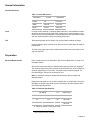
General Information
Overall Dimensions
Level For best results, cabinets, countertops walls and floors in the installation location
should be as level and plumb as possible. Variance may cause damage to coun-
tertops and floors during installation, could jeopardize the seal around the cooktop
and may adversely affect cooking and baking performance.
Tips Tape warming drawer shut to keep it from opening while installing the range.
During installation, place a portion of the box or a piece of cloth under the range to
protect floors.
To make range lighter and easier to handle remove door (see instructions in Use
and Care manual).
Preparation
Electrical Requirements Refer to data plate for more information. See “Product Data Plate” on page 17 for
data plate location.
We recommend that the range be installed with a power cord set (not supplied).
1
The electrical rating of the power cord set must be 120/240 volt, 40 or 50
amperes
minimum (depending on local code). The power cord set shall be marked “For
Use with Ranges.” Always use a new power cord.
Note: In Canada, the range is shipped from the factory with the range cord
already installed.
Ranges are dual rated for use on either 120/240 VAC or 120/208 VAC. Check the
data plate for the kW rating. Reference the kW rating in the table below to deter-
mine amperage requirements.
Table 1: Overall Dimensions
Dimension Inches centimeters
Height
36 91.44 cm
Width
29 5/16” 74.55 cm
Depth
25 5/8” 65.09 cm
1.Not needed for Canadian installations
Table 2: Electrical Specifications
kW Rating Hz Amps Req’d
120/240V 120/208V
13
9.8
60
40 or 50
a
a. Varies by location. Check local codes.
13.8
10.4 60
40 or 50
a

English 4
The electrical outlet must be located in the shaded space in Figure 3.
Verify that wiring to house is adequate
Contact your local utility company to verify that the present electric service to your
home is adequate. In some instances, the size of the wiring to the house and ser-
vice switch must be increased to handle the electrical load demanded by the
range.
Verify that wiring inside house is adequate
Most wiring codes require a separate circuit with separate disconnect switch and
fuses either in the main entrance panel or in a separate switch and fuse box.
The range requires a minimum of a three wire 120/240 or 120/208 volt, 40 or 50
AMP, 60 Hz AC circuit. Check local codes for proper amperage ratings.A four wire
connection is preferred.
Most local building regulations and codes require that electrical wiring be done by
licensed electricians. Be sure to install your range according to the electric codes
in place in your region.
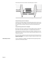
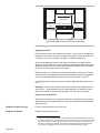
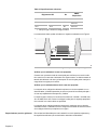
Cabinet Requirements This unit is designed for installation near adjacent walls and projecting surfaces
constructed of combustible materials.
Figure 1: Cooktop Clearances
21” (533.4 mm)
30”
(762 mm)
7 1/2”
(190.5 mm)
3 1/2”
(88.9 mm)
4 1/2”
(114.3 mm)
4 1/2”
(114.3 mm)

English 5
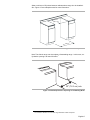
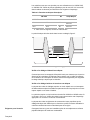
Allow a minimum of 30 inches between cabinets where range is to be installed
1
.
See Figure 2: Cutout Requirements for more information..
Note: The slide-in range can also replace a freestanding range. In this case, ver-
ify that the opening is at least 30 inches.
1
1.In Canada, a clearance of 12 mm from range sidewall to cabinet is required.
Figure 2: Cutout Requirements
Figure 3: Cutout Requirements - Replacing a Free-Standing Model
23 1/16"
(585.4 mm)
30" (762 mm)
30" (76.2 cm) min
.

English 6
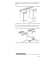
Required Clearance
1
From cooktop to materials above: There must be a minimum clearance of 30
inches between the top of the cooking surface and the bottom of an unprotected
wood or metal cabinet. See Figure 4: Cabinet Preparation.
24 inches is acceptable when the bottom of the wood or metal cabinet is protected
by (a) not less than 1/4" of flame retardant material which must be covered with
(b) not less than No. 28 MSG sheet metal, 0.015 inch stainless steel’ or 0.024 inch
aluminum or copper.
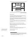
From range walls to adjacent materials: See Figure 4: Cabinet Preparation. No
clearance is required from unit walls to adjacent vertical combustible walls on
rear, right or left.
2
Clearance from range top to adjacent vertical walls must be at least 4”.
Note: Some cabinet finishes cannot survive the temperatures allowed by U.L.,
particularly self-cleaning ovens; the cabinets may discolor or stain. This is most
noticeable with laminated cabinets.
Prepare Walls and Floor
Seal any holes in the walls or floor. Remove any obstructions (extra electrical or
gas connections, etc.) so that range will rest against wall properly.
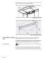
Countertop Requirements Countertops must be smooth and level.
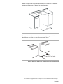
Mounting Requirements Install Anti-Tip Bracket
Figure 4: Cabinet Preparation
1.Instructions were determined using standard American cabinets. Standard base cabinets mea-
sure 36" high x 24" deep. Cabinets over the cooking surface and cabinets adjacent to those over
the cooking surface measure 13 inches deep from backwall. If nonstandard cabinets are used,
care should be taken to alter dimensions accordingly.
2.In Canada, a clearance of 12 mm from range sidewall to cabinet is required.
30" (76.2 cm)
min. centered
30" (76.2 cm) min.
4" (10.2 cm)
min.
4" (10.2 cm)
min.
no clearance required
(12 mm clearance required in Canada)

English 7
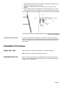
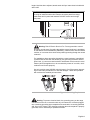
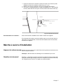
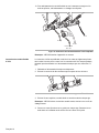
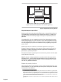
1. Adjust height of range and level by rotating the adjustable leg supports on the
bottom of the range, using 1-1/4" wrench.
2. Measure to locate bracket position as shown in See Figure 5: Anti-Tip
Bracket.
3. Secure bracket with 2 screws adequate for mounting surface (i.e., for wood
floor use wood screws, for concrete floor use concrete anchors and screws).
Ventilation Recommendations We strongly recommend the installation of a ventilation hood above this appli-
ance. For most kitchens a certified hood rating of not less than 300 CFM is recom-
mended. The range hood must be installed according to instructions furnished
with the hood.
Installation Procedure
Apply Foam Tape Apply foam tape to underside of cooktop trim in one continuous piece.
Note: DO NOT use caulk or glue/adhesive of any kind.
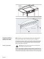
Install Backwall Trim Note: This step is only required if the countertop does not connect behind the
range (i.e.; when replacing a free-standing range). See “Cabinet Requirements”
on page 6 for more information
Figure 5: Anti-Tip Bracket
flush against
cabinet wall
floor
cabinet wall
rear wall
anti-tippin g
device
1 9/16" (39.7 mm)
from rear wall to center of screw hole

English 8
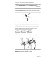
Install 2 screws through holes in trim and in range backwall. See Figure 6: Back-
wall Trim Strip and Figure 7: Install Backwall Trim Strip
Connect Electric - Range
Cord
Note: In Canada, the range is shipped from the factory with the range cord
already installed. Continue to “Complete the installation” on page 15.
For installations other than those in Canada, connect the range cord at the termi-
nal block (See next page for detailed instructions). Access the terminal block by
removing the cover in the lower right hand corner of the range back panel.
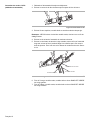
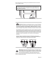
Install Strain Relief Warning: The strain relief provided with your range cord must be properly
installed.
Place strain relief in knockout below terminal block. See Figure 8: Strain Relief
Knockout. Feed range cord through hole and strain relief up to terminal block.
Allow for slack in the cord between the strain relief and terminal block. Once cord
Figure 6: Backwall Trim Strip
Figure 7: Install Backwall Trim Strip
Backwall
Trim Strip
Back of Range

English 9
length/ slack has been adjusted, attach strain relief per instructions included with
strain relief.
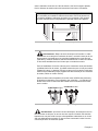
Warning: To prevent electrical shock, the grounding prong on the range
cord should not be cut or removed under any circumstances. It must be plugged
into a matching grounding type receptacle and connected to a correctly polarized
240- Volt circuit. If there is any doubt as to whether the wall receptacle is properly
grounded, have it checked by a qualified electrician.
Figure 8: Strain Relief Knockout
Figure 9: Grounding Requirements
Tip: The knockout panel below the terminal block can be removed from
the range to install the strain relief: Remove knockout panel from range,
install strain relief in panel and reattach. DO NOT remove entire range
back panel.
Warning: Risk of Electric Shock or Fire. Frame grounded to neutral
through a ground strap. Grounding through the neutral conductor is prohibited
for new branch-circuit installations (1996 NEC), mobile homes, and recreationa
l
vehicles, or in an area where local codes prohibit grounding through the neutra
l
conductor.
For installations where grounding through the neutral conductor is prohibited,
(a) disconnect the link from the neutral, (b) use grounding terminal or lead to
ground unit, (c) connect neutral terminal to lead branch circuit neutral in usual
manner (when the appliance is to be connected by means of a cord kit, use 4-
conductor cord for this purpose).
Use only cord kits rated 125/250 volts (minimum), 40 or 50 amperes (depend-
ing on local code) and labeled “For Use with Ranges”. Strain relief provided
with cord must be installed per instructions

English 10
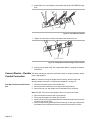
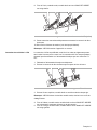
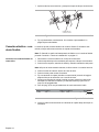
Four Wire Range Cord Connection
(Recommended Method)
1. Disconnect electrical power at breaker box.
2. Remove the terminal block cover to expose the terminal block
3. Remove top nut, star washer, and round washer from each post.
Note: DO NOT remove last round washer, last nut or internal wiring leads.
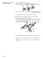
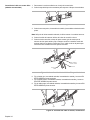
4. Remove screw from bottom end of ground strap.
5. Remove ground strap from center post, rotate so that wide end is at top and
attach wide end to range through hole below junction box. Attach green wire
on top of ground strap. Tighten Screw.
6. Attach red wire, round washer, star washer and nut IN THIS ORDER to left
post.
7. Attach white wire, round washer, star washer and nut IN THIS ORDER to cen-
ter post.
Figure 10: 4 Wire Connection
Figure 11: Four Wire Range cord Connection - Ground Strap and Wire
ground strap
green ground screw
ground wire

English 11
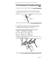
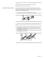
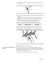
8. Attach black wire, round washer, star washer and nut IN THIS ORDER to right
post.
9. Tighten all connections securely and replace terminal block cover.
10. Properly secure strain relief (see previous section).
Note: DO NOT plug in range at this time.
Three Wire Range Cord Connection The Four Wire Connection (above) is preferred, but where local codes and ordi-
nances permit grounding through neutral and where conversion to four wire is
impractical, the unit may be connected to the power supply via a three wire con-
nection.
1. Disconnect electrical power at breaker box.
2. Remove the terminal block cover to expose the terminal block.
3. Remove top nut, star washer, and round washer from each post.
Note: DO NOT remove last round washer, last nut or internal wiring leads.
4. Attach white wire, round washer, star washer and nut IN THIS ORDER on top
of ground strap on center post.
5. Attach red wire, round washer, star washer and nut IN THIS ORDER to left
post.
Figure 12: Four Wire Range Cord Connection (continued)
red
white
black
Figure 13: Terminal Block

English 12
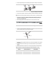
6. Attach black wire, round washer, star washer and nut IN THIS ORDER to right
post.
7. Tighten all connections securely and replace terminal block cover.
8. Properly secure strain relief. See “Install Strain Relief” on page 8 for detailed
instructions.
Connect Electric - Flexible
Conduit Connection
The range can also be connected via flexible conduit. If using this method, always
use the lugs supplied.
Note: In Canada, the range is shipped from the factory with the range cord
already installed. Continue to “Complete the installation” on page 15.
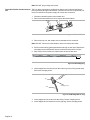
Four Wire Flexible Conduit Connec-
tion
1. Disconnect electrical power at the breaker box.
2. Remove the terminal block cover to expose the terminal block.
3. Remove the top nut, star washer, and round washer from each post.
Note: DO NOT remove last round washer, last nut or internal wire leads.
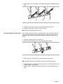
4. Remove screw from bottom end of ground strap.
5. Remove ground strap from center post. Discard.
6. Attach one terminal lug (packaged with this manual) through hole below termi-
nal block with ground screw.
7. Place one terminal lug (packaged with this manual) on each post. Replace the
star washer and round washer and secure with 20 inch pounds of torque.
Figure 14: Three Wire Connection
Figure 15: Completed Three Wire Range Cord Connection
red
white
black
ground strap
green ground screw

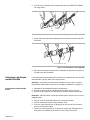
English 13
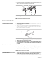
8. Strip 3/8 (9.53 mm) inches of insulation from the end of the wire.
9. Insert the insulated grounding wire into the lug below the terminal block.
10. Insert stripped end of white wire into the center lug. Secure the clamping-
screw.
11. Insert stripped end of red wire into the left lug. Secure clamping screw.
12. Insert black wire into the right lug. Secure clamping screw. Tighten each
clamping screw with the appropriate torque (see table).
13. Properly secure flexible conduit at knockout on angle and at supply side junc-
tion box. The wiring is now complete.
Figure 16: Wire Stripping
Figure 17: Attaching Wire to Lug
Table 3: Appropriate Torque Levels for Aluminum or Copper Wire
Gauge Torque (in./lbs.) Torque (Nm)
6
35 3.95
8
25 2.82
Figure 18: Completed Four Wire Flexible Conduit Connection
3/8 “
lug
clamping screw
wire
red wire
white wire
green
ground
screw
black wire
green ground wire

English 14
Note: DO NOT plug in range at this time.
Three Wire Flexible Conduit Connec-
tion
The Four Wire Connection is preferred, but where local codes and ordinances
permit grounding through neutral and/or conversion to four wire is impractical, unit
may be connected to the power supply via a three wire connection.
1. Disconnect electrical power at the breaker box.
2. Remove the terminal block cover to expose the terminal block.
3. Remove the top nut, star washer, and round washer from each post.
Note: DO NOT remove last round washer, last nut or internal wire leads.
4. Place one terminal lug (packaged with this manual) on each post. Replace the
star washer and round washer and secure with 20 inch pounds of torque.
5. Strip 3/8 (9.53 mm) inches of insulation from the end of each wire.
6. Insert stripped end of white wire into the center lug on top of the ground strap.
Secure the clamping screw.
.
7. Insert stripped end of red wire into the left lug. Secure clamping screw.
8. Insert stripped end of black wire into the right lug. Secure clamping screw.
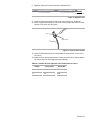
Figure 19: Terminal Block
Figure 20: Wire Stripping
Figure 21: Attaching Wire to Lug
3/8 “
lug
clamping screw
wire

English 15
9. Tighten each clamping screw with the appropriate torque (See table below).
10. Properly secure flexible conduit at knockout panel on range and at supply
side junction box. The wiring is now complete.
Note: DO NOT plug in range at this time.
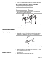
Complete the installation
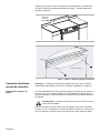
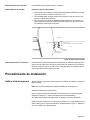
Adjust Levelling Legs 1. Line up range in front of opening.
2. Measure back left corner of opening from floor to top of countertop.
3. Measure back left corner of range to bottom of cooktop trim. Use a wrench to
adjust leveling leg until this height is the same as the corner dimension.
4. Repeat in right back corner.
5. Adjust front leveling legs so that the bottom of the cooktop trim is ½" higher
than the corresponding countertop surface.
Slide Range into Opening 1. Plug in power cord.
2. Dampen countertop and foam tape with soapy water.
Table 4: Appropriate Torque Levels for Aluminum or Copper Wire
Gauge Torque (in./lbs.) Torque (Nm)
6
35 3.95
8
25 2.82
Figure 22: Completed Three Wire Flexible Conduit Connection
green ground screw
Figure 23: Adjust the Front Leveling Leg
adjustable leg
wrench
drawer

English 16
3. Slide range into opening, being careful not to damage countertops, floors, or
the range drawer front. Do not apply pressure to cooktop when sliding into
position.
Tip: Remove the drawer to prevent damage.
Check Back of Range for Proper
Installation
1. When properly installed, the cooktop trim around the back of the range will
rest lightly on the countertop.
2. There should not be any gap between the countertop and the trim; however,
the weight of the range must not rest on the countertop. Look under the range
to verify that both back legs are resting solidly on the floor. Also verify that the
left range leg is under the anti-tip bracket.
Caution: Verify that the weight of the range is not resting on the counterrop. This
could result in damage to the countertop and the appliance.
3. If the back legs are not resting solidly on the floor or the left leg is not under
the anti-tip bracket, slide range out, adjust legs and slide back in.
Adjust Front of Range for Proper
Installation
1. Adjust front leveling legs so that the cooktop trim rests snugly against the
countertop all the way around.
2. Verify that both front legs are resting solidly on the floor.
3. Use a level to verify that the range is level and plumb.
Test the Installation
Turn on Power at Breaker Caution: If the display flashes and beeps, the polarity of the wiring may be
reversed. Reversed polarity can damage the range and can result in electrical
shock hazard. Immediately switch off power at the breaker and return to “Connect
Electric - Range Cord” on page 8.
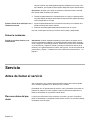
Before Calling
Service
See Use and Care Manual for troubleshooting information. Refer to the Warranty
in the Use and Care Manual.
To reach a service representative, see the contact information at the front of the
manual. Please be prepared with the information printed on your product data
plate when calling.
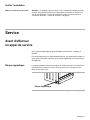
Service

English 17
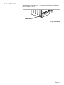
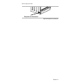
Product Data Plate The data plate shows the model and serial number. Refer to the data plate on the
appliance when requesting service. It is located on the frame near the drawer.
Open the drawer to view it.
Figure 24: Data Plate
Data Plate

Table des matières
Questions?
1.800.944.2904
www.boschappliances.com
5551 McFadden Ave.
Huntington Beach, CA 92649
Nous attendons vos nouvelles !
Sécurité . . . . . . . . . . . . . . . . . . . . . . . . . . . . . . . . . . . . . . . . . . . . . . . . . . . . 1
Installation . . . . . . . . . . . . . . . . . . . . . . . . . . . . . . . . . . . . . . . . . . . . . . . . . . 2
Avant de commencer . . . . . . . . . . . . . . . . . . . . . . . . . . . . . . . . . . . . . . . . . . . . . . . . . . . . . . . . . . .2
Marche à suivre d'installation . . . . . . . . . . . . . . . . . . . . . . . . . . . . . . . . . . . . . . . . . . . . . . . . . . . . . 7
Service . . . . . . . . . . . . . . . . . . . . . . . . . . . . . . . . . . . . . . . . . . . . . . . . . . . 17
Avant d'effectuer un appel de service . . . . . . . . . . . . . . . . . . . . . . . . . . . . . . . . . . . . . . . . . . . . . .17
La page est en cours de chargement...
La page est en cours de chargement...
La page est en cours de chargement...
La page est en cours de chargement...
La page est en cours de chargement...
La page est en cours de chargement...
La page est en cours de chargement...
La page est en cours de chargement...
La page est en cours de chargement...
La page est en cours de chargement...
La page est en cours de chargement...
La page est en cours de chargement...
La page est en cours de chargement...
La page est en cours de chargement...
La page est en cours de chargement...
La page est en cours de chargement...
La page est en cours de chargement...
La page est en cours de chargement...
La page est en cours de chargement...
La page est en cours de chargement...
La page est en cours de chargement...
La page est en cours de chargement...
La page est en cours de chargement...
La page est en cours de chargement...
La page est en cours de chargement...
La page est en cours de chargement...
La page est en cours de chargement...
La page est en cours de chargement...
La page est en cours de chargement...
La page est en cours de chargement...
La page est en cours de chargement...
La page est en cours de chargement...
La page est en cours de chargement...
La page est en cours de chargement...
La page est en cours de chargement...
La page est en cours de chargement...
-
 1
1
-
 2
2
-
 3
3
-
 4
4
-
 5
5
-
 6
6
-
 7
7
-
 8
8
-
 9
9
-
 10
10
-
 11
11
-
 12
12
-
 13
13
-
 14
14
-
 15
15
-
 16
16
-
 17
17
-
 18
18
-
 19
19
-
 20
20
-
 21
21
-
 22
22
-
 23
23
-
 24
24
-
 25
25
-
 26
26
-
 27
27
-
 28
28
-
 29
29
-
 30
30
-
 31
31
-
 32
32
-
 33
33
-
 34
34
-
 35
35
-
 36
36
-
 37
37
-
 38
38
-
 39
39
-
 40
40
-
 41
41
-
 42
42
-
 43
43
-
 44
44
-
 45
45
-
 46
46
-
 47
47
-
 48
48
-
 49
49
-
 50
50
-
 51
51
-
 52
52
-
 53
53
-
 54
54
-
 55
55
-
 56
56


dans d''autres langues
- English: Bosch HEI7032C/01 Installation guide
- español: Bosch HEI7032C/01 Guía de instalación
Documents connexes
-
Bosch HEI7052U/08 Guide d'installation
-
Siemens HES445U/02 Manuel utilisateur
-
Bosch HDI7052U/09 Guide d'installation
-
-
Bosch Appliances HDI7132C/02 Manuel utilisateur
-
Bosch HEI8054U/01 Guide d'installation
-
-
-
Bosch HES7132U/04 Guide d'installation
-