
The RA24DS Retrore Draw Screen Kit is used with the RA24ZC Zero Clearance kit tted with in the model RF24B(N/P)
Retrore B-Vent heater (see Assembly Overview below).
This kit requires the use of a cast fret and an outer trim listed in the RA24ZA instruction manual.
Using the draw screen closed can reduce the danger of burning oneself on the hot surface of the window.
RA24DS
RETROFIRE DRAW SCREEN KIT
INSTALLATION INSTRUCTIONS
CSA approved for use only with
Model RA24ZC Zero Clearance Kit on the heater Model RF24BN/BP
4001091/02
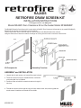
Rod
RH Mesh
Screen
LH Mesh
Screen
Inner Frame
ASSEMBLY and INSTALLATION
Unpack the kit and ensure you have all the parts in hand.
The draw screen kit may be installed before or after the
outer extruded trim is installed.
Position of the rod with the screw hole tab on the right of
the loop.
Thread the curtain rod through the rings of each mesh screen side, ensuring that the
mesh screen’s handles are towards in the middle.
1.
2.
3.
4.
Assembly OverviewKit Components

2
Designed and Manufactured by
Miles Industries Ltd.
190 – 2255 Dollarton Highway, North Vancouver B.C, CANADA. V7H 3B1
Tel. (604) 984-3496 Fax (604) 984-0246
www.milesreplaces.com
© Copyright Miles Industries Ltd., 2006
Rod
4001012
Mesh Screen Assembly Panel (2)
4001013
Inner Frame 4000997AZ
Screw 100A757
REPAIR PARTS LIST
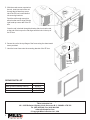
Fix the rod
through
this hole
With the mesh screen mounted on
the rod, insert one end of the rod
through the left hand top corner
tab of the ZC box located behind
the mounting brackets.
Push the rod through enough to
allow its other end to align with the
right hand top corner tab of the ZC
box.
Once the rod is hooked through both tabs, slide it so that the tab
at the end of the loop on the rod aligns with the hole in the top of
the ZC box.
Secure the rod to the top ange of the frame using the sheet-metal
screw provided.
Hook the inner frame onto the mounting bracket of the ZC box.
5.
6.
7.

3
Le Pare-étincelles amovible Retrore RA24DS est conçu pour utilisation avec le foyer Retrore à évacuation de type B
RF24B(N/P) lorsque le foyer est installé dans la caisse à dégagement zéro Retrore RA24ZC (voir le concept montré ci-
dessous).
Le pare-étincelles amovible doit être installé avec une base chantournée et une bordure extérieure tel qu’indiqué dans le
manuel d’installation du Kit à dégagement zéro RA24ZC.
Le pare-étincelles fermé réduit les risques de brûlures pouvant être causées par le contact avec la surface chaude de la
fenêtre du foyer.
RA24DS
PARE-ÉTINCELLES AMOVIBLE RETROFIRE
MANUEL D’INSTALLATION
Homologué par la CSA pour utilisation exclusive avec
le Kit à dégagement zéro RA24ZC et le foyer RF24BN/BP
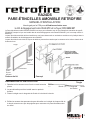
Tringle
Panneau
droit du
pare-
étincelles
Panneau
gauche
du pare-
étincelles
Encadrement
ASSEMBLAGE et INSTALLATION
Déballez le kit et assurez-vous d’avoir en main toutes les
pièces.
Le pare-étincelles peut être installé avant ou après la
bordure.
Placez la tringle avec la languette de xation à la droite de la boucle.
Enlez les anneaux des panneaux du pare-étincelles sur la tringle de chaque côté de
la boucle; assurez-vous que les poignées pour manoeuvrer le pare-étincelles soient
au milieu.
1.
2.
3.
4.
ConceptContenu du kit
Tringle
Gauche
Droite
Languette
de xation
Boucle

4
Conçu et fabriqué par
Miles Industries Ltd.
190 – 2255 Dollarton Highway, North Vancouver, C.-B., CANADA. V7H 3B1
Tél. : (604) 984-3496 Téléc. : (604) 984-0246
www.milesreplaces.com
© 2006, Miles Industries Ltd. Tous droits réservés.
Tringle
4001012
Panneau du pare-étincelles (2)
4001013
Encadrement 4000997AZ
Vis à métal 100A757
PIÈCES DE REMPLACEMENT
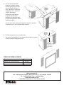
Fixez la
tringle ici, à
l’aide de la
vis fournie
Une fois le pare-étincelles
monté sur la tringle, insérez
l’embout gauche de la tringle
dans la languette située en
haut, à gauche de la caisse à
dégagement zéro, derrière le
support de montage.
Poussez la tringle dans la
languette gauche an de
permettre de l’accrocher dans
la languette opposée, en haut à
droite de la caisse.
Une fois accrochée, glissez la tringle an d’aligner sa languette
de xation au trou de vis du dessus de la caisse.
Fixez la tringle avec la vis à métal fournie.
Accrochez l’encadrement sur les supports de montage de chaque
côté de la caisse à dégagement zéro.
5.
6.
7.
-
 1
1
-
 2
2
-
 3
3
-
 4
4


dans d''autres langues
- English: Valor RA24DS Owner's manual
Documents connexes
-
Valor RA24FS Le manuel du propriétaire
-
-
-
-
-
-
-
-
-