SICK KT5W-2 P/NXXX3, KT5G-2P/NXXX4 Mode d'emploi
- Taper
- Mode d'emploi

ENGLISHENGLISH
Contrast Scanner
Operating Instructions
Safety Specifications
> Read the operating instructions before starting operation.
> Connection, assembly, and settings only by competent technicians.
> Protect the device against moisture and soiling when operating.
> No safety component in accordance with EU machine guidelines.
Proper Use
The KT5-2 contrast scanner is an opto-electronic sensor and is used for
optical, non-contact detection of contrast marks.
Starting Operation
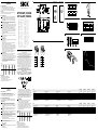
1 Equipment plug horizontally (H) and vertically (V) adjustable. Connect
and secure cable receptacle tension-free. The following apply for
connection in B: brn = brown, blu = blue, blk = black, gra = gray, wht
= white. Outputs: Q
P
or Q
N
. Connect the scanner according to the B
connection chart.
2 Release delay see: Timing element (corresponding to type label, see
below). Select light emission side; replace the lens with a dummy
screwed connection if necessary.
3
Select the insertion position so that the light spot enters the marking ver-
tically. Pay attention to the key; see below: A = vertical, B = horizontal.
4 Mountthesensorwithmountingholesattheplace(e.g.,deection
roller) where the test object has the least horizontal and vertical
movement. Pay attention to the scanning range when doing this (see
technical data and chart: x = scanning range; y = relative sensitivity).
Align the horizontal and vertical movements of the test object using
correspondingly long markings.
Makesurethatsensormovementdoesnotinuencethescanning
distance.
5 Inthecaseofobjectswithreectiveorshinysurface,tiltsensorby10°
to15°relativetosurface.
Connect cables.
6 KT5W-2XXXX3 only:
ET: External teach input for programming the switching threshold using
an external signal.
Saving the settings:
Set light and dark switch or via control cable: D: dark mark on light
background, L: light mark on dark background.
High signal at ET. Move the format with the mark into the scanning
distance of the light spot of the KT. Input ET switched with LOW signal.
The switch threshold is permanently stored. The sensor selects the
light source (red, blue or green) automatically. Material speed during
teach-inprocedure:min.25mm/s-max.300mm/s.
Lock the teach-in button against unintentional activation with “RUN”.
teach-incanbetriggerediftheswitchsettingisnotdened.
7 KT5G-2XXXX4 only:
The switching threshold of the contrast scanner tracks the existing
contrast dynamically. A teach-in process is not required.
Setlightanddarkswitchandthecontrast(F:ne;C:coarse)resolved
by means of a switch on the operating panel or via control line: dark:
dark mark on light background; light: light mark on dark background.
At switch position LINE, the operating panel is blocked.
Only settings which are made via the control line F / C and L / D are
accepted. The example shows the method of function for setting
“coarse” in the dark mode.
Key
KT5W- 2P 1 1 1 3
Light source Output Light spot Scanning
distance /
Light spot
Timing
element
Teach-in
G = green light
W = Red-green
-blue
P = PNP
N = NPN
1=horizontal
2 = vertical
1=10mm/
1.2x4.2mm
2=20mm/
1.5x5mm
3=40mm/
1.1x4.2mm
1=without
2=20ms
Time delay
3 = dynamic
teach-in
4=automa-
tic function
Maintenance
SICK light barriers are maintenance-free.
We recommend doing the following regularly:
- clean the external lens surfaces
- check the screw connections and plug-in connections.
Nomodicationsmaybemadetodevices.
DEUTSCHDEUTSCH
Kontrasttaster
Betriebsanleitung
Sicherheitshinweise
> Vor der Inbetriebnahme die Betriebsanleitung lesen.
> Anschluss, Montage und Einstellung nur durch Fachpersonal.
> Gerät bei Inbetriebnahme vor Feuchte und Verunreinigung schützen.
> Kein Sicherheitsbauteil gemäß EU-Maschinenrichtlinie.
Bestimmungsgemäße Verwendung
Der Kontrasttaster KT5-2 ist ein optoelektronischer Sensor und wird zum
optischen, berührungslosen Erfassen von Kontrastmarken eingesetzt.
Inbetriebnahme
1 Gerätestecker nach horizontal (H) und vertikal (V) schwenkbar.
Leitungsdose spannungsfrei aufstecken und festschrauben. Für
Anschluss in B gilt: brn = braun, blu = blau, blk = schwarz, gra = grau,
wht = weiß. Ausgänge: Q
P
oder Q
N
. Taster laut Anschlussschema B
anschließen.
2 Abfallverzögerung: Zeitglied (entspr. Typenschlüssel, s. u.). Lichtaus-
trittsseite wählen, ggf. Objektiv gegen Blindverschraubung aus-
tauschen.
3 Einbaulagesowählen,dassLichtecklängsindieMarkierungeintritt.
Dabei Typenschlüssel beachten, s. u.; A = längs, B = quer.
4 Sensor mit Befestigungsbohrungen an Stelle (z. B. Umlenkrolle) mon-
tieren, an der das Prüfobjekt die geringsten Seiten- und Höhenbewe-
gungen ausführt. Dabei Tastweite beachten (s. technische Daten und
Diagramm,x=Tastweite,y=relativeEmpndlichkeit).
Seiten- und Höhenbewegungen des Prüfobjektes durch entsprechend
lange Markierungen ausgleichen.
BewegungendesSensorsmitTastweiteneinussausschließen.
5 BeispiegelndenoderglänzendenObjektoberächenSensorum10°
bis15°zurMaterialoberächeneigen.
Leitungen anschließen.
6 Nur KT5W-2XXXX3:
ET: Eingang Extern Teach, zur Programmierung der Schaltschwelle über
externes Signal.
Einstellung Speicherung:
Hell- / Dunkelumschalter einstellen oder über Steuerleitung:
D: Dunkle Marke auf hellem Grund, L: Helle Marke auf dunklem Grund.
High Signal an ET. Format mit Druckmarke im Tastabstand durch
denLichteckdesKTbewegen.EingangETmitLOWSignalschalten.
Schaltschwelleistnichtüchtiggespeichert.DerSensorwähltdie
Lichtquelle (rot, blau oder grün) automatisch. Materialgeschwindigkeit
beimTeach-Vorgang:min.25mm/s-max.300mm/s.
Den Teach-in-Knopf gegen unbeabsichtigtes Betätigen mit „RUN“
sperren.BeiundenierterSchalterstellungkannkeinTeach-inaus-
gelöst werden.
7 Nur KT5G-2XXXX4:
Die Schaltschwelle wird dynamisch dem vorliegenden Kontrast
nachgeführt. Ein Teach-in Vorgang ist nicht erforderlich.
Hell- / Dunkelumschalter und aufzulösender Kontrast
(F:ne;C:coarse)einstellenoderüberSteuerleitung:dark:Dunkle
Marke auf hellem Grund; light: Helle Marke auf dunklem Grund.
Bei Schalterstellung LINE ist das Bedienfeld gesperrt, es werden
nur Einstellungen über die Steuerleitung F / C und L / D akzeptiert.
Die Graphik zeigt die Funktionsweise in Stellung „coarse“ in der
Betriebsart „dunkelschaltend“.
Typenschlüssel
KT5W- 2P 1 1 1 3
Lichtquelle Ausgang Q Lichtfleck Tastweite /
Lichtfleck
Zeitglied Teach-in
G = Grünlicht
W = Rot-grün-
blau
P = PNP
N = NPN
1=längs
2 = quer
1=10mm/
1,2x4,2mm
2=20mm/
1,5x5mm
3=40mm/
1,1x4,2mm
1=ohne
2=20ms
Abfallverzö-
gerung
3 = dynami-
sches Teach-in
4=automati-
sche Funktion
Wartung
SICK-Lichtschranken sind wartungsfrei.
Wir empfehlen, in regelmäßigen Abständen
–dieoptischenGrenzächenzureinigen,
– Verschraubungen und Steckverbindungen zu überprüfen.
Veränderungen an Geräten dürfen nicht vorgenommen werden.
KT 5W-2P / NXXX3
KT 5G-2P / NXXX4
A
B
1 5
2
3
4
6
7
KT5 W-2 P1XXX3 W-2 NXXX3 G-2 PXXX4 G-2N XXX4
Supply voltage U
B
Versorgungsspannung U
B
Tension d‘alimentation U
B
Tensão de força U
B
DC10…30V
1)
DC10…30V
1)
DC10…30V
1)
DC10…30V
1)
Switching output Schaltausgang Sortie logique Saída de circuito PNP NPN PNP NPN
Signal sequence Signalfolge Frequence Sequência do sinais 10000/s
2)
10000/s
2)
10000/s
2)
10000/s
2)
Response time Ansprechzeit Temps de réponse Tempo de reação 50ms 50ms 50ms 50ms
Enclosure rating Schutzart Type de protection Tipo de proteção IP 67 IP 67 IP 67 IP 67
Ambient operating temperature Betriebsumgebungstemperatur Température ambiante Temperatura ambiente de operação -10…+55°C -10…+55°C -10…+55°C -10…+55°C
1)
Limit values
Residual ripple max. 5 V
PP
U
B
connections reverse polarity protected
2)
Scanningratio1:1
1)
Grenzwerte
Restwelligkeit max. 5 V
SS
U
B
-Anschlüsse verpolsicher
2)
Tastverhältnis1:1
1)
Valeurs limites
Ondulation résiduelle maxi 5 V
SS
Raccordements U
B
protégés contre les inversions de polarité
2)
Rapportdedétection1:1
1)
Valores limite
ondulação residual máx. 5 V
SS
Conexões U
B
protegidas contra inversão de polos
2)
Relaçãodeexploraçao1:1
KT5 W-2 P1XXX3 W-2 NXXX3 G-2 PXXX4 G-2N XXX4
Tensione di alimentazione U
B
Tensión de alimentación U
B
电源电压U
B
供給電圧 U
B
DC10…30V
1)
DC10…30V
1)
DC10…30V
1)
DC10…30V
1)
Uscita di commutazione Salida de conexión 输出电流I
max.
最大出力電流 I
max.
PNP NPN PNP NPN
Sequenza signali Secuencia de señales
最小信号序列 最小信号シーケンス
10000/s
2)
10000/s
2)
10000/s
2)
10000/s
2)
Tempo di risposta Tiempo de reacción
触发时间 応答時間
50ms 50ms 50ms 50ms
Tipo di protezione Tipo de protección
保护种类 保護等級
IP 67 IP 67 IP 67 IP 67
Temperatura ambiente circostante Temperatura ambiente de servicio
工作环境-温度 使用周囲温度
-10…+55°C -10…+55°C -10…+55°C -10…+55°C
1)
Valori limite
ondulazione residua max. 5 V
SS
U
B
-collegamenti con protezione contro inversione di poli
2)
Rapportodiricezione1:1
1)
Valores límite
ondulación residual max. 5 V
SS
Conexiones U
B
a prueba de inversión de polaridad
2)
Relacióndeexploración1:1
1)
极限值剩余波
纹度 max. 5 V
SS
U
B
-接头防反接
2)
感应比:1:1
1)
限界値:
残留リップル 最大 5 V
SS
U
B
接続 逆接保護
2)
検出比1:1
Q
L
I
N
E
C
C
F
F
light
dark
TEACH
D
L
RUN
RUN
Q
T
E
A
C
H
9
28
56
21
30.4
M5
M5
16
13
28
52
80
25
40
53
3
3
L+
Q
M
L /
D
F /
C
1
4
2
brn
blk
wht
3
blu
5
gra
L+
Q
M
ET
L /
D
1
4
2
brn
blk
wht
3
blu
5
gra
ON
ON
Q
P
Q
N
Q
P
Q
N
tt tt tttt
AB
15 °
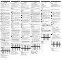
Switching threshold
30
50
70
90
100
80
60
40
20
10
%
10
(0.39)
Distance in mm (inch)
20
(0.78)
30
(1.18)
40
(1.57)
50
(1.97)
0
Q
P
---------------------------------------------------------8008976.16I50120COMAT ------------------------------------------------------
KT 5W-2P / NXXX3 KT 5G-2P / NXXX4
KT 5W-2P / NXXX3 KT 5G-2P / NXXX4
Morerepresentativesandagenciesatwww.sick.com∙Subjecttochange
withoutnotice∙Thespeciedproductfeaturesandtechnicaldatadonot
represent any guarantee.
WeitereNiederlassungenndenSieunterwww.sick.com∙Irrtümer
undÄnderungenvorbehalten∙AngegebeneProdukteigenschaftenund
technische Daten stellen keine Garantieerklärung dar.
Plusdereprésentationsetd’agencesàl’adressewww.sick.com∙Sujetà
modicationsanspréavis∙Lescaractéristiquesdeproduitettechniques
indiquées ne constituent pas de déclaration de garantie.
Paramaisrepresentanteseagências,consultewww.sick.com∙Alterações
poderãoserfeitassemprévioaviso∙Ascaracterísticasdoprodutoeos
dados técnicos apresentados não constituem declaração de garantia.
Altrirappresentantiedagenziesitrovanosuwww.sick.com∙Contenuti
soggettiamodichesenzapreavviso∙Lecaratteristichedelprodottoei
dati tecnici non rappresentano una dichiarazione di garanzia.
Másrepresentantesyagenciasenwww.sick.com∙Sujetoacambiosin
previoaviso∙Lascaracterísticasylosdatostécnicosespecicadosno
constituyen ninguna declaración de garantía.
欲了解更多代表机构和代理商信息,请登录 www.sick.com∙
如有更改 , 不另行通知∙对所给出的产品特性和技术参数
的正确性不予保证。
その他の営業所は www.sick.com よりご覧ください∙予告なし
に変更されることがあります∙ 記載されている製品機能およ
び技術データは保証を明示するものではありません。
BZ int49
Detailed addresses and further locations at www.sick.com
Australia
Phone +61 (3) 9457 0600
1800 33 48 02 – tollfree
Austria
Phone +43 (0) 2236 62288-0
Belgium/Luxembourg
Phone +32 (0) 2 466 55 66
Brazil
Phone +55 11 3215-4900
Canada
Phone +1 905.771.1444
Czech Republic
Phone +420 234 719 500
Chile
Phone +56 (2) 2274 7430
China
Phone +86 20 2882 3600
Denmark
Phone +45 45 82 64 00
Finland
Phone +358-9-25 15 800
France
Phone +33 1 64 62 35 00
Germany
Phone +49 (0) 2 11 53 010
Greece
Phone +30 210 6825100
Hong Kong
Phone +852 2153 6300
Hungary
Phone +36 1 371 2680
India
Phone +91-22-6119 8900
Israel
Phone +972 97110 11
Italy
Phone +39 02 27 43 41
Japan
Phone +81 3 5309 2112
Malaysia
Phone +603-8080 7425
Mexico
Phone +52 (472) 748 9451
Netherlands
Phone +31 (0) 30 229 25 44
New Zealand
Phone +64 9 415 0459
0800 222 278 – tollfree
Norway
Phone +47 67 81 50 00
Poland
Phone +48 22 539 41 00
Romania
Phone +40 356-17 11 20
Russia
Phone +7 495 283 09 90
Singapore
Phone +65 6744 3732
Slovakia
Phone +421 482 901 201
Slovenia
Phone +386 591 78849
South Africa
Phone +27 10 060 0550
South Korea
Phone +82 2 786 6321/4
Spain
Phone +34 93 480 31 00
Sweden
Phone +46 10 110 10 00
Switzerland
Phone +41 41 619 29 39
Taiwan
Phone +886-2-2375-6288
Thailand
Phone +66 2 645 0009
Turkey
Phone +90 (216) 528 50 00
United Arab Emirates
Phone +971 (0) 4 88 65 878
United Kingdom
Phone +44 (0)17278 31121
USA
Phone +1 800.325.7425
Vietnam
Phone +65 6744 3732
SICKAG,Erwin-Sick-Strasse1,D-79183Waldkirch
2006/42/EC
2006/42/EC
NO
SAFETY

FRANÇAISFRANÇAIS
Détecteur de contrastes
Instructions de Service
Conseils de sécurité
> Lire les Instructions de Service avant la mise en marche.
> Installation,raccordementetréglagenedoiventêtreeectuésquepar
dupersonnelqualié.
> Lors de la mise en service, protéger l’appareil de l’humidité et des
saletés.
> N’est pas un composant de sécurité au sens de la directive européenne
concernant les machines.
Utilisation correcte
Le détecteur de contraste KT5-2 est un capteur optoélectronique qui
s’utilise pour la saisie optique sans contact de repères lumineux contrastés.
Mise en service
1 Seulement pour les versions à connecteur : Le connecteur peut
pivoterhorizontalement(H)etverticalement(V).Encherlaboîteà
conducteurs sans aucune tension et la visser. Pour le raccordement
dans B on a: brn = brun, blu = bleu, blk = noir, gra = gris, wht = blanc.
Sorties : Q
PNP
o Q
NPN
. Raccorder le détecteur conformément au schéma
de circuit B.
2 Temporisation à la retombée; Relais temporisateur (conformément
au code des modèles, voir ci-dessous) : Choisir le côté de sortie de
la lumière, remplacer éventuellement l’objectif par un embout vissé
d’obturation.
3 Choisir la position de montage de façon que la tache de lumière
pénètre longitudinalement dans le repère. Ce faisant, tenir compte du
code des modèles, voir ci-dessous ; A = longitudinalement,
B = transversalement.
4 Installerlecapteur,munidetrousdexation,àl’endroit
(par ex. poulie de renvoi) où l’objet à examiner exécute les mouve-
ments latéraux et verticaux les plus faibles. Ce faisant, tenir compte de
la distance de détection (voir les caractéristiques techniques et
le diagramme, x = distance de détection, y = sensibilité relative).
Compenser les mouvements latéraux et verticaux de l’objet à examiner
au moyen de repères de longueur appropriée.
Excluretoutmouvementducapteurpouvantinuersurladistancede
détection.
5 Danslecasd’objetsàsurfacebrillanteourééchissanteinclinerle
capteurde10°à15°parrapportàlasurfacedumatériau.
Raccorder les conducteurs.
6 KT5W-2XXXX3 uniquement :
ET : Entrée Extern Teach (Apprentissage externe), permet la program-
mation du seuil de détection au moyen d’un signal externe.
Réglage Mémorisation :
Régler le commutateur clair / sombre ou par l’intermédiaire du câble
de commande : D : Marquage sombre sur fond clair, L : Marquage clair
sur fond sombre. Signal HAUT à la borne ET. Déplacer le format muni
du marquage imprimé à travers le spot lumineux du KT, à la distance
prévue pour la détection. Signal BAS à l’entrée ET.
Le seuil de commutation est stocké dans la mémoire non volatile.
Le capteur choisit automatiquement la source de lumière (rouge,
bleu ou vert). Vitesse du matériel lors du processus d’apprentissage :
minimum25mm/s-maximum300mm/s.
Verrouiller le bouton d’apprentissage contre tout actionnement invo-
lontaire en réglant sur « RUN ». Si le commutateur se trouve dans une
positionindénie,onnepeutpasdéclencherl’apprentissage.
7 KT5G-2XXXX4 uniquement :
Le seuil de commutation fait l’objet d’un réajustement dynamique en
fonctionducontrasteexistant.Iln’estpasnécessaired’eectuerun
proccesus d’apprentissage.
Réglerlecommutateurclair/sombreetlecontraste(F:n;C:grossier)
à résoudre ou bien, à l’aide du câble de commande : dark : repère
sombre sur fond clair ; light : repère clair sur fond sombre.
Lorsque le commutateur est en position LINE, le tableau de com-
mande est verrouillé, l’appareil n’accepte que les réglages F / C
etL/Deectuésaumoyenducâbledecommande.Lediagramme
illustre le principe de fonctionnement en position « grossier » dans le
mode « commutation sombre ».
Code des modèles
KT5W- 2P 1 1 1 3
Source
lumière
Source Q Tache Distance
de détection / tache
Relais
temporisateur
Teach-in
G = lumière
W = Rouge -
bleue - verte
P = PNP
N = NPN
1=
longitudi-
nalement
2 =
transver-
salement
1=10mm/
1,2x4,2mm
2=20mm/
1,5x5mm
3=40mm/
1,1x4,2mm
1=sans
2=20ms
temporisation
à la retombée
3 = Teach-in
dynamique
4=Fonction
automatique
Maintenance
Les barrières lumineuses SICK sont sans entretien.
Nous vous recommandons de procéder régulièrement
- au nettoyage des surfaces optiques
- au contrôle des liaisons vissées et des connexions.
Neprocédezàaucunemodicationsurlesappareils.
ITALIANOITALIANO
Sensore di contrasto
Istruzioni per l'uso
Avvertimenti di sicurezza
> Leggere prima della messa in esercizio.
> Allacciamento, montaggio e regolazione solo da parte di personale
qualicato.
> Durante la messa in esercizio proteggere da umidità e sporcizia.
> Non componente di sicurezza secondo la Direttiva macchine EN.
Impiego conforme allo scopo
Il sensore di contrasto KT5-2 è un sensore optoelettronico che viene impie-
gato per il rilevamento ottico a distanza di marchi di contrasto.
Messa in esercizio
1 Solo con spine:
Spina apparecchio orientabile in orizzontale (H) e in verticale (V).
Inserire scatola esente da tensione e avvitare stringendo. Per col-
legamento B osservare: brn = marrone, blu = blu, blk = nero, gra =
grigio, wht = bianco. Uscite: Q
PNP
o Q
NPN
. Collegare il sensore secondo
lo schema B.
2 Ritardo di caduta; Temporizzatore (secondo codice modello, v. sotto).
Scegliere il lato di uscita luce, sull’altro lato sostituire l’obiettivo con
un tappo a vite.
3 Eettuareilmontaggioinmodocheilpuntoluminosoentri
nell’apposita demarcazione nel senso della lunghezza. Attenenersi a
quanto indicato nel codice modello, v. sotto; A = senso della lung.,
B = senso trasv.
4 Montareilsensoreconiforidissaggionelpunto(ades.carrucoladi
rinvio)incuil’oggettoeettuamenomovimentiorizzontalieverticali.
Tenere conto della distanza di ricezione (cf. Scheda tecnica e dia-
gramma, x=distanza di ricezione, y=sensibilità relativa).
Compensare i movimenti orizzontali e verticali dell’oggetto tramite
demarcazioni di lunghezza adeguata.
Escluderemovimentidelsensorechepossanoinuenzareladistanza
di ricezione.
5 Consuperciriettentioppurebrillantiinclinaredi10
°
-15
°
rispetto
allasuperciedell’oggetto.
Collegare i cavi.
6 Solo KT5W-2XXXX3:
ET: Entrata Extern Teach, per la programmazione del limite di com-
mutazione tramite segnale esterno.
Impostazione memoria:
Impostare commutatore chiaroscuro oppure con commutazione esterna:
D: macchia scura su sfondo chiaro, L: macchia chiara su sfondo scuro.
High Signal a ET. Spostare il formato con la marca di stampa alla
distanza di rilevamento attraverso la macchia di luce del KT. L’entrata
ET è commutata con LOW Signal. La soglia di commutazione è memo-
rizzata permanentemente. Il sensore sceglie automaticamente la fonte
di luce (rossa, azzurra oppure verde). Velocità del materiale durante il
procedimentoditeach:min.25mm/s-max.300mm/s.
Bloccare il tasto di Teach-in contro l’attivazione involontaria con
«RUN».Quandolaposizionedell’interruttorenonèdenitanonè
possibile iniziare un Teach-in.
7 Solo KT5G-2XXXX4:
La soglia di commutazione viene adattata dinamicamente al contrasto
attuale. Non è necessario un procedimento di Teach-in.
Impostare il commutatore chiaro / scuro e il contrasto
(F:ne;C:coarse)darisolvereoppureimpostaretramitecomando:
dark: marcatura scura su sfondo chiaro; light: marcatura chiara su
sfondo scuro.
Quando l’interruttore è in posizione LINE il pannello di comando è
bloccato e accetta soltanto impostazioni tramite il comando F / C
e L / D. L’illustrazione indica il modo di funzionamento nella posizione
«coarse» per il modo di esercizio «commutante scuro».
Codice modello
KT5W- 2P 1 1 1 3
Fonte di luce Uscita Q Punto
luminoso
Distanza
di ricezione /
punto luminoso
Temporiz-
zatore
Teach-in
G = luce verde
W = Rossa-
verde-azzurra
P = PNP
N = NPN
1=senso
della lung.
2 = senso
trasv.
1=10mm/
1,2x4,2mm
2=20mm/
1,5x5mm
3=40mm/
1,1x4,2mm
1=senza
2=20ms
Ritardo di
caduta
3 = Teach-in
dinamico
4=Funzione
automatica
Manutenzione
Le barriere fotoelettriche SICK sono esenti da manutenzione.
Consigliamo di pulire in intervalli regolari
-lesupercilimiteottiche
-vericareicollegamentiaviteegliinnestiaspina.
Nonèconsentitoeettuaremodicheagliapparecchi.
ESPAÑOLESPAÑOL
Palpador de contraste
Manual de Servicio
Observaciones sobre seguridad
> Leer el Manual de Servicio antes de la puesta en marcha.
> Conexión, montaje y ajuste solo por personal técnico.
> A la puesta en marcha proteger el aparato contra humedad y suciedad.
> No es elemento constructivo de seguridad según la Directiva UE sobre
maquinaria.
Empleo para usos debidos
El palpador de contraste KT5-2 es un sensor opto-electrónico empleado
para la detección óptica y sin contacto de marcas de contraste.
Puesta en marcha
1 Solo en conectores:
Conector del aparato orientable en horizontal (H) y vertical(V). Insertar
y atornillar bien la caja de conexiones sin tensión. Para conectar en B:
brn=marrón, blu=azul, blk=negro, gra=gris, wht=blanco. Salidas: Q
PNP
y Q
NPN
. Conectar el pulsador de acuerdo al esquema de conexiones B.
2 Abertura retardada; Elemento temporizador (aplicar de acuerdo a la
clave de tipos, ver abajo). Seleccionar el lado de salida de la luz, en
caso dado, recambiar el objetivo por atornilladura ciega.
3 Elegir la posición de montaje de forma que la mancha de luz caiga
longitudinalmente en la marca. Tener en cuenta la clave de tipos, ver
abajo; A = longitudinal, B = transversal.
4 Montarelsensorconlasperforacionesdejaciónenellugar(p.
ejem., polea de reenvío) donde los objetos a controlar ejecuten el
menor movimiento lateral y de altura. Tener en cuenta aquí el alcance
de exploración (ver características técnicas y el diagrama, x=alcance
de exploración, y=sensibilidad relativa).
Compensar los movimientos laterales y de altura de los objetos a
controlar mediante marcas correspondiente-mente largas.
Excluirmovimientosdelsensorconinuenciadealcancedepal-
pación.
5 Consuperciesdeobjetosreectantesobrillantesinclinarelsensor
entre10°y15°hacialasuperciedelmaterial.
Conectar los conductores.
6 Solo KT5W-2XXXX3:
ET: Entrada Extern Teach, para programación del umbral de conexión a
través de señal externa.
Ajuste memorización:
Ajustar el conmutador claro / oscuro, o vía línea de mando: D: Marca
oscura sobre fondo claro, L: Marca clara sobre fondo oscuro.
Señal «High» a ET. Pasar el soporte con la marca impresa por el punto
luminoso de KT, dentro del alcance de detección. Activar la entrada
ET con señal «LOW». El umbral de activación está almacenado de
forma no volátil. El sensor elige automáticamente la fuente de luz
(rojo, azul o verde). Velocidad de material durante el proceso de
enseñanza:mín.25mm/s-máx.300mm/s.
Bloquear el botón de «Teach-in» mediante «RUN» contra un
accionamientoinvoluntario.Encasodeunaposiciónindenida
del conmutador, no puede activarse la función de «Teach-in».
7 Solo KT5G-2XXXX4:
El umbral de activación es adaptado de forma dinámica al contraste
actual. Un proceso de «Teach-in» no es necesario.
Ajustar el conmutador de claro / oscuro y la resolución de contraste
(F:ne;C:coarse)deseada,ovíalíneadecontrol:dark:marcaoscura
sobre fondo claro; light: marca clara sobre fondo oscuro.
En la posición de conmutador LINE, está bloqueado el panel de
mando, solamente se aceptan los ajustes a través de la línea de
controlF/CyL/D.Elgrácomuestraelfuncionamientoenla
posición «coarse», en el modo de servicio «conexión en oscuro».
Clave de tipos
KT5W- 2P 1 1 1 3
Fuente de luz Salida Q Mancha
de luz
Alcance
de exploración /
mancha de luz
Elemento
temporizador
Teach-in
G = luz verde
W = Roja-
verde-azul
P = PNP
N = NPN
1=alo
largo
2 = a través
1=10mm/
1,2x4,2mm
2=20mm/
1,5x5mm
3=40mm/
1,1x4,2mm
1=sin
2=20ms
Abertura
retardada
3 = Teach-in
dinámico
4=Función
automática
Mantenimiento
Las barreras fotoeléctricas SICK no precisan mantenimiento.
En intervalos regulares, recomendamos
-limpiarlassuperciesópticasexternas
- comprobar las uniones roscadas y las conexiones.
Nosepermiterealizarmodicacionesenlosaparatos.
PORTUGU SPORTUGU S
Foto-célula de contraste
Instruções de operação
Instruções de segurança
> Antes do comissionamento dev ler as instruções de operação.
> Conexões, montagem e ajuste devem ser executados exclusivamente
porpessoaldevidamentequalicado.
> Guardar o aparelho ao abrigo de umidade e sujidade.
> Não se trata de elemento de segurança segundo a Diretiva Máquinas da
União Europêa.
Utilização devida
A foto-célula de contraste KT5-2 é um sensor opto-eletrônico que é uti-
lizado para a análise ótica, sem contato, de marcas contrastantes.
Comissionamento
1 Vale somente para as versões com conetores:
Os conetores dos aparelhos giram na horizontal (H) e na vertical (V).
Enaracaixadecabossemtorçõeseaparafusá-la.Paraaligação
elétrica em B é: brn = marron, blu = azul, blk = preto, gra = cinzento,
wht = branco. Saídas: Q
PNP
e Q
NPN
. Ligar o sensor conforme o esquema
de ligações B.
2 Retardo de desacionamento; Elemento temporizador: Selecionar o
lado de saída da luz, se for caso disso, substituir a objetiva por união
roscada cega.
3 Selecionar a posição de montagem por forma que o ponto de luz
se encontre dentro da marcação. Levar em conta o código de tipo,
verabaixo; A = ao comprido, B= posição transversal.
4 Montar o sensor executando perfurações no lugar (por ex. rolo de
inversão), em que o objeto de controle executa os menores movimen-
tos laterais e de elevação. Atender, durante este processo, ao raio
de exploração (ver dados técnicos e diagrama, x=raio de exploração,
y=sensibilidade relativa).
Compensar os movimentos laterais e de elevação do objeto de
controle através de marcações de comprimento adequado.
Excluirmovimentosdosensor,inuenciandooraiodeexploração.
5 Tratando-sedesuperfíciesdeobjetosquereetemoubrilhaminclinar
osensorpor10°até15°comrelaçãoàsuperfíciedomaterial.
Fazer a cablagem elétrica.
6 Só KT5W-2XXXX3:
ET: Entrada do sinal externo Teach, para programação do valor limite
de ligação através do sinal externo.
Regulação da memória:
Ajustar o comutador de claro / escuro ou através de condutor de con-
trolo: D marca escura sobre fundo claro, L: marca clara sobre fundo
escuro. Sinal high em ET. Deslocar formato com marca de impressão
na distância de exploração mediante o ponto luminoso do KT. Entrada
ET ligada com sinal SLOW. O limiar de comutação está memorizado
de modo não volátil. O sensor selecciona automaticamente a fonte
luminosa (vermelha, azul ou verde).
Velocidade do material durante o processo Teach:
mín.25mm/s-máx.300mm/s.BloquearobotãoTeach-in
mediante “RUN” contra accionamento involuntário. Se a posição do
interruptorforindenida,nãoserápossívelaccionaroTeach-in.
7 Só KT5G-2XXXX4:
O limiar de comutação é ajustado automaticamente ao contraste
existente. Não é necessário um procedimento Teach-in.
Ajustarocomutadorclaro/escuroeocontraste(F:ne;C:coarse)a
ser activado ou através do circuito de comando: dark: Marca escura
sobre fundo claro; light: Marca clara sobre fundo escuro.
Com o selector na posição LINE, o painel de comando está blo-
queado, só sendo aceites ajustes efectuados através do circuito de
comandoF/CeL/D.Ográcomostraofuncionamentonaposição
“coarse”, no modo de operação “comutação para escuro”.
Código do tipo
KT5W- 2P 1 1 1 3
Fonte
luminosa
Saída Q Ponto
luminoso
Distance
de détection /
ponto luminoso
Relais
temporisateur
Teach-in
G = luz verde
W = Vermelha-
verde-azul
P = PNP
N = NPN
1=Posição
horizontal
2 = Posição
transversal
1=10mm/
1,2x4,2mm
2=20mm/
1,5x5mm
3=40mm/
1,1x4,2mm
1=sem
2=20ms
Retardo de
desaciona-
mento
3 = Teach-in
dinâmico
4=Função
automática
Manutenção
As barreiras de luz SICK não requerem manutenção.
Recomendamos que se efetue em intervalos regulares
- uma limpeza das superfícies ópticas
-umavericaçãodasconexõesroscadasedosconectores.
Nãosãopermitidasmodicaçõesnoaparelho.
中文中文
对比扫描仪
操作规程
安全须知
> 调试前请阅读操作说明。
> 仅允许由专业人员进行接线、安装和设置。
> 调试时应防止设备受潮或脏污。
> 本设备非欧盟机械指令中定义的安全部件。
正确使用须知
对比扫描仪
KT5-2 是一种光电传感器,用于非接触式光学检测对比标志。
调试
1 设备插头可以沿水平 (H) 和垂直 (V) 方向转动。 在不通电的情况下插上
并拧紧电缆插座。
针对 B 的接口:brn = 棕色,blu = 蓝色,blk = 黑
色,
gra = 灰色,wht = 白色。输出端:Q
P
或 Q
N
。根据连接图 B 连接传
感器。
2 释放延时:定时器(相应的型号代码,见下文) 选择光出口侧,必要时
使用螺丝堵头更换镜头。
3 选择安装位置,确保光斑沿纵向(垂直方向)出现于标记中。 此时应注
意型号代码,见下文;
A = 纵向,B = 横向。
4 通过固定孔将传感器安装在相应位置(例如换向辊), 测试对象在此位
置处的侧向和高度方向移动最少。此时应注意感应距离(参见技术数据
和图表,
x = 感应距离,y = 相对灵敏度)。
通过适当长度的标记对测试对象的侧向和高度方向的移动进行补偿。
确保传感器的移动不会对感应距离产生影响。
5 对象表面存在反射或具有光泽时,须将传感器相对于材料表面倾斜10
至15°。
连接导线。
6 仅 KT5W-2XXXX3:
ET
:外部示教输入端,用于通过外部信号编程开关阈值。
保存设置:
设置明/暗转换开关,或者通过控制导线:
D:浅色背景上的深色标记,L:深色背景上的浅色标记。
ET 上的 High 信号。通过 KT 的光斑移动格式(带具有感应间距的打印标
记)。
使用 LOW 信号切换 ET 输入端。开关阈值永久保存。 传感器自动
选择光源(红色、蓝色或绿色)。示教过程中的材料速度:最低
25 mm / s -
最高300mm/s。
使用“RUN”锁定示教按钮,防止意外操作。开关位置未定义时,无法激
活示教。
7 仅 KT5G-2XXXX4:
开关阈值随当前对比度动态变化。 无需示教过程。
设置明/暗转换开关和待分辨的对比度(F:精确;C:粗糙),或者通过控
制导线:
dark:浅色背景上的深色标记,light:深色背景上的浅色标记。
在 LINE 开关位置时,操作区被锁定,仅通过控制导线 F / C 和 L / D 接受
设置。
图示为在“暗接通”运行模式下“粗糙”位置的功能原理。
型号代码
KT5W- 2P 1 1 1 3
光源
输出端 Q
光斑 感应距离 /
光斑
定时器 示教
G = 绿光
W = 红-绿-蓝
P = PNP
N = NPN
1=纵向
2 = 横向
1=10mm/
1,2x4,2mm
2=20mm/
1,5x5mm
3=40mm/
1,1x4,2mm
1= 无
2 = 20ms
释放延时
3 = 动态示教
4= 自动功能
保养
SICK 光电开关无需保养。
我们建议,定期
- 清洁镜头检测面
- 检查螺丝接头和插头连接。
不得对设备进行任何改装。
日本語日本語
コントラストスキャナ
取扱説明書
安全上の注意事項
> 使用を開始する前に取扱説明書をお読みください。
> 接続、取付けおよび設定できるのは専門技術者に限ります。
> 装置を使用開始する際には、濡れたり汚れたりしないように保護して
ください。
> 本製品は EU 機械指令の要件を満たす安全コンポーネントではありま
せん。
用途
コントラストスキャナ
KT5-2 は光電センサで、対象物を光学技術により非
接触で反射光量の差(コントラスト)を検知するための装置です。
使用開始
1 デバイスプラグは水平(H)および垂直(V)に動かすことができま
す。
ケーブルプラグをケーブルに張力がかからないように差し込み、
ネジ止めします。
B の接続:brn = 茶、blu = 青、blk = 黒、
gra = 灰、wht = 白。出力:Q
P
または Q
N
センサーを接続図 B に従って
接続します。
2 遅延オフ:時限素子(型式コードに対応、下記参照)。 発光側を選択
し、必要に応じてレンズをネジ締結式ダミーと交換します。
3 光点がマークの長手方向に入るように取付け位置を決めます。 この
時、型式コードに注意します(下記参照)。
A = 長手方向、B = 横方
向。
4 センサの固定用ボアのある方を、検査対象物の上下左右の動きが最も
小さい場所(例えば偏向ローラー)に取付けます。その際、検出範囲
にご注意ください(技術仕様およびグラフを参照。
x = 検出範囲、y =
相対感度)。
検出対象物の上下左右の動きを、適切な長さのマークで補正します。
センサの動きで検出範囲が変わらないようにします。
5 対象物の表面が鏡面状であったり光る場合には、その表面に対して
10°~15°だけセンサーの向きを傾けます。
ケーブルを接続します。
6 KT5W-2XXXX3 のみ:
ET
:外部ティーチ入力端子、外部信号のスイッチング閾値のプログラ
ミング用。
保存設定:
ライト/ダークスイッチを設定、または制御ケーブルを介して:
D:明るい背景に暗いマーク、L:暗い背景に明るいマーク。
ET の High 信号検出間隔のプリントマークが付いたフォーマット
を、
KT の光点を通して移動させます。 LOW 信号のある入力 ET を切り
替えます。これでスイッチング閾値が不揮発性に保存されました。
セ
ンサーは光源(赤、青、緑)を自動的に選択します。ティーチプロセ
スにおける材料速度:最小
25 mm / s ~ 最大300mm/sまで。
ティーチインボタンが不意に「RUN」に入らないようにロックしま
す。スイッチが未設定の場合には、ティーチインのトリガーをかけら
れません。
7 KT5G-2XXXX4 のみ:
スイッチング閾値は、既存のコントラストに動的に適応します。
ティーチインのプロセスは必要ありません。
ライト/ダークスイッチおよび分解するコントラスト
(
F:ne、C:coarse)を設定、または制御ケーブルを介して:ダー
ク:明るい背景に暗いマーク、ライト:暗い背景に明るいマーク。
スイッチが LINE に設定されているとコントロールパネルがロックさ
れ、設定は制御ケーブル
F / C および L / D を介してのみ受け入れられ
ます。
図は、「ダークオン」モードで、「coarse」のスイッチ位置の
機能を示しています
型式コード
KT5W- 2P 1 1 1 3
光源
出力 Q
光点 検出範囲 /
光点
時限素子 ティーチイン
G =
緑のランプ
W = 赤-緑-青
P = PNP
N = NPN
1=長手方向
2 = 横方向
1=10mm/
1,2x4,2mm
2=20mm/
1,5x5mm
3=40mm/
1,1x4,2mm
1= なし
2 = 20ms
遅延オフ
3 = ダイナミ
ックティーチ
イン
4=自動機能
メンテナンス
SICK の光電スイッチはメンテナンス不要です。
推奨する定期的な保全作業
- レンズ境界面の清掃
- ネジ締結と差込み締結の点検
デバイスに変更を加えることは一切禁止されています。
-
 1
1
-
 2
2


SICK KT5W-2 P/NXXX3, KT5G-2P/NXXX4 Mode d'emploi
- Taper
- Mode d'emploi
dans d''autres langues
Documents connexes
-
SICK LUTM Mode d'emploi
-
-
-
-
-
SICK LUT3 Mode d'emploi
-
-
-
-