
THERMADOR.COM
Installation
GUIDE
Built-in MicroDrawer
®
Microwave Oven MD24WS
MD30WS


Table of
CONTENTS
SAFETY DEFINITIONS ��������������������������������������������������������� 2
IMPORTANT SAFETY INSTRUCTIONS ���������������������������3-5
SAFETY CODES AND STANDARDS ������������������������������� 3
GROUNDING INSTRUCTIONS ��������������������������������������� 3
CLEARANCES AND DIMENSIONS �������������������������������� 3
UNPACKING YOUR MICRODRAWER
®
MICROWAVE OVEN ����������������������������������������������������������� 6
IMPORTANT NOTES TO THE INSTALLER �������������������� 6
IMPORTANT NOTES TO THE CONSUMER ������������������� 6
MICRODRAWER
®
MICROWAVE OVEN
MEASUREMENTS ������������������������������������������������������������� 7-8
ANTI-TIP BLOCK ������������������������������������������������������������������ 9
ELECTRICAL REQUIREMENTS ������������������������������������������ 9
DRAWER INSTALLATION �������������������������������������������������� 10
BSH HOME APPLIANCES CORPORATION SUPPORT ��� 10
.

English 2
WARNING
This indicates that death or serious injuries may
occur as a result of non-observance of this warning.
CAUTION
This indicates that minor or moderate injuries may
occur as a result of non-observance of this warning.
NOTICE: This indicates that damage to the appliance or
property may occur as a result of non-compliance with
this advisory.
Note: This alerts you to important information and/or tips.
WARNING
• Installation must be performed by a qualified
installer.
• INSTALLER: Leave these instructions with the appli-
ance after installation.
• IMPORTANT: Save this installation manual for local
electrical inspector's use.
• HOMEOWNER: Please read and save these
instructions for future reference.
WARNING
If the information in this manual is not followed exactly,
fire or shock may result causing property damage or
personal injury.
Safety Definitions

English 3
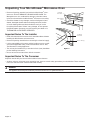
Clearances and Dimensions
• For safety considerations do not install drawer in any
combustible cabinetry which is not in accord with the
stated clearances and dimensions in the "MicroDrawer
®
Microwave Oven Measurements" section following.
See Figure 3 (standard installation) or Figure 4 (flush
installation).
• Dimensions that are shown in Figure 3 (standard
installation) or Figure 4 (flush installation) must be used.
Given dimensions provide minimum clearance. Locate
electrical outlet in the shaded area in the upper left-hand
corner of the cutout. See Figure 6.
• Supporting surface must be solid and level. Pay special
attention to the floor of the cabinet opening on which
the MicroDrawer
®
microwave oven will sit. The floor of
the opening should be constructed of plywood strong
enough to support the weight of the oven (approxi-
mately 100 pounds).
• Check the location where the MicroDrawer
®
microwave
oven
will be installed for proper electrical supply.
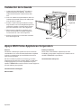
• Your oven can be built into a cabinet or wall as a stand-
alone unit or under a built-in gas or electric wall oven
and the followings:
INDUCTION
COOKTOPS
ELECTRIC
COOKTOPS
GAS
COOKTOPS
RANGETOPS
CIT304TB
CIT304TM
CIT30XWBB
CIT365TB
CIT367TGS
CIT367TG
CIT367TM
CIT367TMS
CIT36XWBB
CIT36XWB
CEM305TB
CET305TB
CEM366TB
CET366TB
SGS305TS
SGSP305TS
SGSX305TS
SGSXP305TS
SGS365TS
SGSP365TS
SGSX365TS
SGSXP365TS
PCG305W
PCG364WD
PCG364WL
PCG366W
• Check to be sure that there is a clearance of 2 inches or
greater between the top of the MicroDrawer
®
microwave
oven
unit and the bottom of a built-in wall oven above it.
• The microwave interior will accommodate a 9" x 13"
oblong dish or a bag of microwave popcorn.
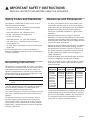
Safety Codes and Standards
This appliance complies with the latest version of one or
more of the following standards:
• CAN/CSA C22.2 No. 61 - Household Cooking Ranges
• UL 858 - Household Electric Ranges
• CAN/CSA C22.2 No. 150 - Microwave Ovens
• UL 923 - Microwave Cooking Appliances
• UL 507 - Electric Fans
• CAN/CSA C22.2 No. 113 - Fans and Ventilators
• CSA C22.2 No. 64 - Household Cooking and Liquid-
Heating Appliances
• UL 1026 - Electric Household Cooking and Food Serving
Appliances
It is the responsibility of the owner and the installer to
determine if additional requirements and/or standards apply
to specific installations.
Grounding Instructions
This appliance must be grounded. In the event of an electri-
cal short circuit, grounding reduces the risk of electric shock
by providing an escape wire for the electric current. This
appliance is equipped with a cord having a grounding wire
with grounding plug. The plug must be plugged into a outlet
that is properly installed and grounded.
WARNING
Improper grounding can result in a risk of electric
shock.
Consult a qualified electrician if the grounding instructions
are not completely understood, or if doubt exists as to
whether the appliance is properly grounded.
Do not use an extension cord. If the power supply cord is too
short, have a qualified electrician install an outlet near the
appliance.
The installer must perform a ground continuity check on
the power outlet box before beginning the installation to
insure that the outlet box is properly grounded. If not prop-
erly grounded, or if the outlet box does not meet Electrical
Requirements, a qualified electrician should be employed to
correct any deficiences.
IMPORTANT SAFETY INSTRUCTIONS
READ ALL INSTRUCTIONS BEFORE USING THE APPLIANCE

English 4
IMPORTANT SAFETY INSTRUCTIONS
READ ALL INSTRUCTIONS BEFORE USING THE APPLIANCE
INSTALLER: LEAVE THESE INSTRUCTIONS WITH THE
APPLIANCE AFTER INSTALLATION IS COMPLETE.
IMPORTANT: SAVE THESE INSTRUCTIONS FOR THE
LOCAL ELECTRICAL INSPECTOR'S USE.
WARNING
If the information in this manual is not followed
exactly, fire or shock may result causing property
damage or personal injury.
WARNING
Do not repair, replace or remove any part of the
appliance unless specifically recommended in
the manuals. Improper installation, service or
maintenance can cause injury or property damage.
Refer to this manual for guidance. All other servicing
should be done by a qualified technician.
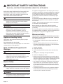
Appliance Handling Safety
Unit is heavy and requires at least two people or proper
equipment to move.
Do not lift appliance by door handle.
Hidden surfaces may have sharp edges. Use caution when
reaching behind or under appliance.
State of California Proposition 65
Warnings:
WARNING
This product can expose you to chemicals including
vinyl chloride, which is known to the State of
California to cause cancer and birth defects or other
reproductive harm. For more information go to
www�P65Warnings�ca�gov
Electric Safety
WARNING
Before you plug in an electrical cord or turn on power
supply, make sure all controls are in the OFF position.
WARNING
The appliance must be disconnected from the source
of supply before attempting the installation.
For appliances equipped with a cord and plug, do not cut or
remove the ground prong. It must be plugged into a matching
grounding type receptacle to avoid electrical shock. If there
is any doubt as to whether the wall receptacle is properly
grounded, the customer should have it checked by a quali-
fied electrician.
If required by the National Electrical Code (or Canadian Elec-
trical Code), this appliance must be installed on a separate
branch circuit.
Installer – show the owner the location of the circuit breaker
or fuse. Mark it for easy reference.
Before installing, turn power OFF at the service panel.
Lock service panel to prevent power from being turned ON
accidentally.
Be sure your appliance is properly installed and grounded by
a qualified technician. Installation, electrical connections and
grounding must comply with all applicable codes.
Microwave Safety
PRECAUTIONS TO BE OBSERVED BEFORE AND DURING
SERVICING TO AVOID POSSIBLE EXPOSURE TO EXCES-
SIVE MICROWAVE ENERGY
• Do not operate or allow the oven to be operated with the
door open.
• Make the following safety checks on all ovens to be ser-
viced before activating the magnetron or other microwave
source, and make repairs as necessary:
1. Interlock operation
2. Proper door closing
3. Seal and sealing surfaces (arcing, wear, and other dam-
age)
4. Damage to or loosening of hinges and latches
5. Evidence of dropping or abuse
• Before turning on microwave power for any service test or
inspection within the microwave generating compartments,
check the magnetron, wave guide or transmission line, and
cavity for proper alignment, integrity, and connection.
• Any damaged or misadjusted components in the interlock,
monitor, door seal, and microwave generation and trans-
mission systems shall be repaired, replaced, or adjusted
by procedures described in this manual before the oven is
released to the owner.
• A microwave leakage check to verify compliance with the
Federal Performance Standard should be performed on
each oven prior to release to the owner.

English 5
IMPORTANT SAFETY INSTRUCTIONS
READ ALL INSTRUCTIONS BEFORE USING THE APPLIANCE
Related Equipment Safety
Remove all tape and packaging before using the appliance.
Destroy the packaging after unpacking the appliance. Never
allow children to play with packaging material.
Never modify or alter the construction of the appliance. For
example, do not remove leveling legs, panels, wire covers or
anti-tip brackets/screws.
WARNING
To reduce the risk of fire, use only metal ductwork.
CAUTION
For general ventilating use only. Do not use to
exhaust hazardous or explosive materials and vapors.

English 6
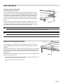
Unpacking Your MicroDrawer
®
Microwave Oven
• Remove all packing materials from inside the MicroDrawer
®
micro-
wave oven. DO NOT REMOVE THE WAVEGUIDE COVER. The
Waveguide cover is a cardboard-like dark grey sheet about 9x10
inches that is attached to the MicroDrawer
®
microwave oven ceiling.
• Check the drawer for any damage, such as misaligned or bent
drawer, damaged drawer seals and sealing surfaces, broken
or loose drawer guides and dents inside the cavity or on the
front side of the drawer. If there is any damage, do not operate
the MicroDrawer
®
microwave oven and contact your dealer or a
THERMADOR
®
AUTHORIZED SERVICER.
Important Notes To The Installer
• Read and understand the contents of this Installation Manual before
installing the MicroDrawer
®
microwave oven.
• Remove all packing material before connecting the electrical supply.
• It is the responsibility of the owner and the installer to assure compli-
ance with all applicable safety codes and standards. See UL 923,
The Microwave Cooking Appliances.
• The unit may be installed using a standard or flush (inset) installation
per the following instructions.
• Be sure to leave these instructions with the consumer.
Important Notes To The Consumer
Keep this manual with your Use and Care Guide for future reference.
• As when using any microwave oven generating heat, there are certain safety precautions you should follow. These are listed
in the Use and Care Guide. Read all and follow carefully.
WARNING
The appliance should only be installed by a licensed electrician or a qualified technician.
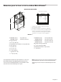
Waveguide
cover
Sealing
surface
Oven cavity
Sealing
surface
Figure 1

English 7
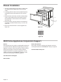
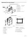
Figure 2
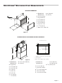
Figure 3
STANDARD INSTALLATION DIMENSIONS AND CLEARANCES
APPLIANCE DIMENSIONS
MicroDrawer
®
Microwave Oven Measurements
Frontview cut out
*
Suggested location of electrical outlet
**
Anti-Tip Block
***
Base should support up to 100 lbs
*
**
***
A
B
C
D
E
G
H
L
O
N
J
K
L
M
I
F
A
C
D
B
F
G
H
I
E
A.
MD24WS (24") 23
7
/8
" (606 mm)
MD30WS (30") 30" (762 mm)
B. 16
5
/16
" (414 mm)
C. 23
3
/8
" (594 mm)
D. 21
7
/8
" (556 mm)
E. 38
3
/8
" (974 mm)
F. 21
5
/8
" (549 mm)
G. 14
5
/8
" (371 mm)
H. 1
11
/16
" (39 mm)
I. Approx. 46" (1,168.4 mm)
A.
MD24WS (24") 24" or 27" (610 or 686 mm)
MD30WS (30") 30" (762 mm)
B. 36" (914 mm)
C. 23
1
/2
" (597 mm)
D. 14
5
/8
" (372 mm)
E. 4" (102 mm)
F. 6" (152 mm)
G. 5" (127 mm)
H. 3
1
/2
" (89 mm)
I. 1
1
/2
" (38 mm)
j.
MD24WS (24") 22
1
/8
" (562 mm)
MD30WS (30") 23" (584 mm) min.
28
1
/4
" (718 mm) max.
K. 14
13
/16
" (376 mm)
L.
7
/8
" (22 mm) overlap
M.
1
/2
" (13 mm) visible area
N.
1
/16
" (2 mm) overlap
O. 1
7
/16
" (36 mm) overlap

English 8
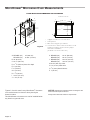
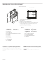
FLUSH INSTALLATION DIMENSIONS AND CLEARANCES
Figure 4
Figures 2, 3 and 4 contain many MicroDrawer
®
microwave
oven measurements for reference when planning the
drawer’s location.
This MicroDrawer
®
microwave oven can be installed below
any electric or gas wall oven.
NOTICE: Always allow sufficient power cord length to the
electrical outlet to prevent tension.
Always check electrical codes for requirements.
MicroDrawer
®
Microwave Oven Measurements
Frontview cut out
Cleat
*
Suggested location of electrical outlet
**
Anti-Tip Block
***
Base should support up to 100 lbs
****
Sides should be finished and extend back to cleat.
Cleats should also be finished, as they may be
visible after installation.
(Cleats are not included with unit.)
*
**
****
A
B
C
D ***
E
G
H
I
J
P
P
M
K
L
O
N
F
A.
MD24WS (24") 27" (686 mm)
MD30WS (30") 30
5
16
" (770 mm)
B. 36" (914 mm)
C. 23
1
/2
" (597 mm)
D. 21
7
/8
" (555 mm) base min. depth
E. 4" (102 mm)
F. 6" (152 mm)
G. 5" (127 mm)
H. 3
1
/2
" (89 mm)
I. 14
5
/8
" (371 mm)
J. 1
5
/8
" (41 mm)
K. MD24WS (24") 22
1
/8
" (562 mm)
MD30WS (30") 28
1
/4
" (718 mm)
L. MD24WS (24") 24
3
/16
" (614 mm)
MD30WS (30") 30
5
/16
" (770 mm)
M. 16
5
/8
" (422 mm) cutout
N.
1
/2
" (13 mm) visible area
O.
1
/4
" (6 mm) base thickness
P. 1" (25 mm)

English 9
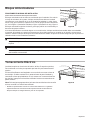
Anti-Tip Block
NORMAL INSTALLATION STEPS
Anti-Tip Block Installation Instructions
The 6-inch Anti-Tip wooden block must be provided by the installer. The anti-
tip block reduces the risk of drawer tipping when installed properly. Install the
anti-tip block 14 13/16 inches above the installation opening floor (where the
unit will sit) for a standard installation or 14 5/8 inches for a flush installation.
See Figure 3 (standard installation) or Figure 4 (flush installation) and Figure
5. The Anti-Tip block prevents serious injury that might result from spilled hot
liquids.
If the MicroDrawer
®
microwave oven is ever moved to a different location, the
Anti-Tip block must also be moved and installed. If the anti-tip block is to be
anchored to the wall make certain that the screws holding it penetrate into the
structural members (studs) behind any covering such as drywall.
CAUTION
Make sure that the screws do not contact any wiring or plumbing that may be present in the wall.
WARNING
The unit can tip and cause spills and potential burns or other injuries if the anti-tip block is not installed correctly.
Electrical Requirements
The unit requires a 120 volt, 60 Hz, 15 AMP (minimum) circuit. It is recom-
mended that the unit be installed to a separate circuit that serves only this
appliance.
This appliance is fitted with a 3-prong grounded electrical plug. Do not modify the
plug or use an adapter. If the plug does not fit with the available receptacle, have
a licensed electrician install a properly grounded outlet before proceeding with
the installation.
Note: If you have any questions about the grounding or electrical instructions,
consult a qualified electrician.
* Unit can also be installed using an electrical outlet in an adjacent cabinet within the
area where the provided electrical cord can reach.
Always check electrical codes for requirements.
Figure 5
4"
5"
Suggested electrical
outlet location*
Anti-Tip
block
6"
3 1/2"
Figure 6
4"
5"
Suggested electrical
outlet location*
Anti-Tip
block
6"
3 1/2"

English 10
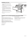
Drawer Installation
1. Place the drawer adjacent to the wall or cabinet open-
ing. Plug the power supply cord into the electrical
outlet.
2. Carefully guide the drawer into the prepared opening.
Avoid pinching the cord between the oven and the
wall.
3. Slide the drawer all the way until the mounting flange
makes contact with the face of the cabinet for stan-
dard installation or side cleats for flush installation.
See Figure 7A.
4. Open the drawer. Using the 4 holes on the drawer as
a template, pre drill the cabinet using a 1/16" bit. See
Figure 7A.
5. Secure the drawer with the 4 screws supplied. See
Figure 7B.
BSH Home Appliances Corporation Support
Service
We realize that you have made a considerable investment in
your kitchen. We are dedicated to supporting you and your
appliance so that you have many years of creative cooking.
Please don’t hesitate to contact our STAR
®
Customer
Support Department if you have any questions or in the
unlikely event that your THERMADOR
®
appliance needs
service. Our service team is ready to assist you.
www�thermador�com/support
800-735-4328
Parts & Accessories
Parts, filters, descalers, stainless steel cleaners and more
can be purchased in the THERMADOR
®
eShop or by phone.
www�thermador-eshop�com
4 Screws
Parts supplied
Figure 7B
Mounting
flange
Figure 7A
Cleat

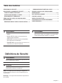
Française 1
Table des matières
DÉFINITIONS DE SÉCURITÉ ������������������������������������������������1
IMPORTANTES CONSIGNES DE SÉCURITÉ ������������������ 2-4
CODES ET NORMES DE SÉCURITÉ �������������������������������������� 2
INSTRUCTIONS DE MISE A LA TERRE �������������������������� 2
DÉGAGEMENTS ET DIMENSIONS ���������������������������������� 2
DÉBALLAGE DE VOTRE FOUR À MICRO-ONDES
MICRODRAWER
®
���������������������������������������������������������������� 5
REMARQUES IMPORT ANTES À L’INSTALLATEUR ������ 5
REMARQUES IMPORT ANTES AU CLIENT �������������������� 5
MESURES POUR LE FOUR À MICRO-ONDES
MICRODRAWER
®
�������������������������������������������������������������� 6-7
BLOC ANTI-BASCULEMENT ���������������������������������������������� 8
PRISE DE COURANT ����������������������������������������������������������� 8
INSTALLATION DU TIROIR ������������������������������������������������� 9
ASSISTANCE DE LA SOCIÉTÉ D'APPAREILS
DOMESTIQUES BSH ����������������������������������������������������������� 9
Définitions de Sécurité
AVERTISSEMENT
Le non-respect de cet avertissement peut entraîner la
mort ou des blessures graves.
ATTENTION
Le non-respect de cet avertissement peut entraîner
des blessures mineures ou modérées.
AVIS : Vous indique que des dommages à l'appareil ou
aux biens peuvent survenir si vous ne respectez pas cet
avertissement.
Remarque : Vous signale des informations importantes ou
des conseils.
AVERTISSEMENT
Si les informations contenues dans ce manuel ne sont
pas suivies à la lettre, un incendie ou un choc peuvent
causer des dommages matériels ou corporels.
AVERTISSEMENT
• Installation doivent être effectués par un installateur
qualifié.
• INSTALLATEUR: Laissez ces instructions avec
l'appareil après l'installation.
• IMPORTANT: Conservez ce manuel d'installation
pour l'inspecteur local électrique.
• PROPRIÉTAIRE: S'il vous plaît lire et conserver ces
instructions pour référence ultérieure.

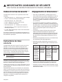
Française 2
Dégagements et dimensions
• Pour raison de SÉCURITÉ, n’installez pas le tiroir à
micro-ondes dans une armoire combustible, ni dans un
endroit qui ne se conforme pas aux dégagements et
aux dimensions précisés aux page 3. Reportez-vous au
Schéma 3 (installation standard) ou Schéma 4 (installa-
tion encastrée).
• Les dimensions indiquées au Schéma 3 (installation
standard) ou Schéma 4 (installation encastrée) doivent
être observées. Ces dimensions offrent un dégagement
minimal. Repérer la prise électrique dans l’aire ombrée
dans le coin gauche supérieur de la découpe. Voir
Schéma 6.
• La surface de contact doit être solide et de niveau.
Prêter une attention particulière au plancher qui
supportera le tiroir. Le plancher de l’ouverture doit être
en contreplaqué assez fort pour supporter le poids du
four et sa propre charge (approximativement 45,5 kg
[100 lb]).
• Vérifier que l’emplacement où le tiroir sera installé aura
une alimentation électrique appropriée.
• Votre four peut être installé dans une armoire, sur un
mur, ou sous un four mural au gaz ou électrique et les
suivantes:
SURFACES DE
CUISSON À
INDUCTION
SURFACES
DE CUISSON
ÉLECTRIQUES
SURFACES DE
CUISSON AU
GAZ
TABLES DE
CUISSON
CIT304TB
CIT304TM
CIT30XWBB
CIT365TB
CIT367TGS
CIT367TG
CIT367TM
CIT367TMS
CIT36XWBB
CIT36XWB
CEM305TB
CET305TB
CEM366TB
CET366TB
SGS305TS
SGSP305TS
SGSX305TS
SGSXP305TS
SGS365TS
SGSP365TS
SGSX365TS
SGSXP365TS
PCG305W
PCG364WD
PCG364WL
PCG366W
• Vérifier que le dégagement du plancher entre le four
mural et le tiroir est au minimum de 2 po (50,8 mm).
• L’intérieur du micro-ondes acceptera facilement un plat
rectangulaire de 9 po x 13 po ou un sac de maïs soufflé
allant au micro-ondes.
Codes et normes de sécurité
Cet appareil est conforme à une ou plusieurs des normes
suivantes :
• CAN/CSA C22.2 No. 61 - Cuisinières pour usage ménager
• UL 858 - Cuisinières électriques domestiques
• CAN/CSA C22.2 No. 150 - Micro-ondes
• UL 923 - Appareils de cuisson à micro-ondes
• UL 507 - Ventilateurs électriques
• CAN/CSA C22.2 No. 113 - Ventilateurs et soufflantes
• CSA C22.2 No. 64 - Cuisine et appareils ménagers de
chauffage de liquides
• UL 1026 - Électrodomestiques cuisine et de l'alimentation
de service Appareils
Il incombe au propriétaire et à l'installateur de déterminer si
des exigences et/ou normes additionnelles s'appliquent pour
des installations spécifiques.
Instructions de mise
a la terre
Cet appareil doit être mis à la terre. En cas de court circuit
électrique, la mise à la terre réduit les risques de choc
électrique en permettant au courant de s'échapper par le
fil de mise à la terre. Cet appareil est équipé d'un cordon
d'alimentation avec fil de mise à la terre et d'une fiche de
mise à la terre. La fiche doit être branchée dans une prise
murale installée correctement et mise à la terre.
AVERTISSEMENT
Une mauvaise mise à la terre peut entraîner un risque
de choc électrique.
Consulter un électricien qualifié si les instructions de mise
à la terre ne sont pas parfaitement comprises, ou en cas de
doute sur la mise à la terre correcte de l'appareil.
N’utilisez pas de rallonge. Si le cordon d’alimentation est trop
court, demander à un électricien qualifié de poser une prise
près de l’appareil.
L'installateur doit effectuer une vérification de continuité de
masse sur la boîte de prise de courant avant de commencer
l'installation pour s'assurer que la zone de prise est correcte-
ment mise à la terre. S'il n'est pas correctement mise à la
terre, ou si la boîte de sortie ne répond pas aux exigences
électriques, un électricien qualifié doit être utilisée pour
corriger les irrégularités.
IMPORTANTES CONSIGNES DE SÉCURITÉ
LIRE TOUTES LES INSTRUCTIONS AVANT D'UTILISER L'APPAREIL

Française 3
IMPORTANTES CONSIGNES DE SÉCURITÉ
LIRE TOUTES LES INSTRUCTIONS AVANT D'UTILISER L'APPAREIL
INSTALLATEUR: LAISSER CES INSTRUCTIONS AVEC
L'APPAREIL FOIS L'INSTALLATION TERMINÉE.
IMPORTANT: CONSERVER CES INSTRUCTIONS POUR
L'UTILISATION DU INSPECTEURS LOCAUX.
AVERTISSEMENT
Si les informations contenues dans ce manuel ne
sont pas exactement, un incendie ou un choc peuvent
causer des dommages matériels ou corporels.
AVERTISSEMENT
Ne pas réparer, remplacer ou supprimer toute partie
de l'appareil à moins d'une recommandation précise
dans les manuels. Une installation, un service ou un
entretien peuvent causer des blessures ou des dom-
mages matériels. Reportez-vous à ce manuel pour
obtenir des conseils. Toutes les autres réparations
doivent être faites par un technicien qualifié.
Appliance manipulation sécurité
L'unité est lourde et nécessite au moins deux personnes ou
un équipement approprié pour le déplacer.
Ne pas soulever l'appareil par la poignée de la porte.
surfaces cachées peuvent avoir des bords tranchants. Faites
preuve de prudence en arrivant derrière ou sous l'appareil.
Avertissement issue de la proposition
65 de l’État de la Californie :
AVERTISSEMENT
Ce produit peut vous exposer à des produits
chimiques, comme du chlorure de vinyle, reconnus
par l’État de la Californie comme causant le cancer,
des malformations congénitales ou d’autres effets
nocifs sur la reproduction. Pour de plus amples
renseignements, consultez
www�P65Warnings�ca�gov
Sécurité électrique
AVERTISSEMENT
Avant de brancher un cordon électrique ou la mise
sous tension d'alimentation, assurez-vous que toutes
les commandes sont en position OFF.
AVERTISSEMENT
L'appareil doit être déconnecté de la source
d'alimentation avant de tenter l'installation.
Pour les appareils équipés d'un cordon et la prise, ne pas
couper ou enlever la broche de terre. Il doit être branché sur
une adaptation de terre prise pour éviter un choc électrique.
En cas de doute quant à la prise murale est correctement
mise à la terre, le client doit le faire vérifier par un électricien
qualifié.
Si requis par le Code national de l'électricité (ou le Code
canadien de l'électricité), cet appareil doit être installé sur un
circuit de dérivation distinct.
Installer - montrer le propriétaire de l'emplacement du
disjoncteur ou fusible. Marquez pour référence facile.
Avant d'installer, couper le courant au niveau du panneau de
service. Verrouiller panneau de service pour éviter une mise
en circuit accidentelle.
Assurez-vous que votre appareil est correctement installé et
mis à la terre par un technicien qualifié. Installation, con-
nexions et mise à la terre électriques doivent se conformer à
tous les codes applicables.
Micro-ondes sécurité
PRECAUTIONS A OBSERVER AVANT ET PENDANT
L'ENTRETIEN POUR ÉVITER UNE EXPOSITION AUX
MICRO-ONDES
• Ne pas utiliser ou permettre au four de fonctionner avec la
porte ouverte.
• Effectuer les contrôles de sécurité suivants sur tous les
fours à desservir avant d'activer le magnétron ou une
autre source de micro-ondes et faire des réparations si
nécessaire:
1. Opération Interlock
2. Fermeture de la porte adéquate
3. Surfaces d'étanchéité et d'étanchéité (arc, usure, et
d'autres dommages)
4. Les dommages ou relâchement des charnières et les
loquets
5. Preuve de chute ou d'abus
• Avant la mise sous tension de micro-ondes pour tout
test de service ou d'inspection dans les compartiments
micro-ondes de production, consultez le magnétron, guide
d'ondes ou d'une ligne de transmission, et de la cavité
pour un bon alignement, l'intégrité, et la connexion.

Française 4
IMPORTANTES CONSIGNES DE SÉCURITÉ
LIRE TOUTES LES INSTRUCTIONS AVANT D'UTILISER L'APPAREIL
• Tous les composants défectueux ou déréglé dans les
systèmes de verrouillage, moniteur, joint de la porte, et
de génération de micro-ondes et de transmission doivent
être réparés, remplacés ou réglés par des procédures
décrites dans ce manuel avant que le four est remis à son
propriétaire.
• Un micro-ondes de fuite contrôle pour vérifier la conformi-
té à la norme fédérale performance devrait être effectuée
sur chaque four avant la libération au propriétaire.
La sécurité du matériel connexe
Enlevez tout le ruban et l'emballage avant d'utiliser l'appareil.
Détruire l'emballage après avoir déballé l'appareil. Ne jamais
laisser les enfants jouer avec les matériaux d'emballage.
Ne modifiez jamais la construction de l'appareil. Par exem-
ple, ne pas retirer les pieds de nivellement, des panneaux,
protège-fils ou anti-bascule supports / vis.
AVERTISSEMENT
Pour réduire le risque d'incendie, utilisez uniquement
des conduits en métal.
ATTENTION
Pour ventilation générale utiliser seulement. Ne pas
utiliser pour évacuer des vapeurs dangereuses ou
explosives.

Française 5
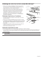
Déballage de votre four à micro-ondes MicroDrawer
®
• Retirer tous les matériaux d’emballage de l’intérieur du four à micro-
ondes MicroDrawer
®
NE PAS RETIRER LE GUIDE D’ONDES qui est
situé au plafond du four à micro-ondes MicroDrawer
®
.
• Vérifier que le four n’a aucun dommage, comme un tiroir mal
aligné ou plié, des joints ou des surfaces d’étanchéité de porte
endommagés, des glissières cassés ou lâches et des bosses
à l’intérieur de la cavité ou sur la façade du tiroir. En cas de
dommages, ne pas faire fonctionner le four à micro-ondes
MicroDrawer
®
et contacter votre détaillant ou un RÉPARATEUR
AUTORISE THERMADOR
®
.
Remarques import antes à l’installateur
• Lire toutes les directives d’installation avant d’installer le four à micro-
ondes MicroDrawer
®
.
• Retirer tous les matériaux d’emballage avant de connecter au secteur.
• Le propriétaire et l'installateur sont responsables d'assurer la conformité
avec tous les codes et toutes les normes de sécurité en vigueur. Voir UL
923, The Microwave Cooking Appliances (Les appareils de cuisson à
micro-ondes).
• L'appareil peut être installé en utilisant une norme ou une couleur (en
médaillon) l'installation en suivant les instructions suivantes.
• Veiller à laisser ces directives au client.
Remarques importantes au client
Conserver ces instructions avec votre mode d’emploi et d’entretien pour référence ultérieure.
• Lors de l’utilisation d’un four à micro-ondes générant de la chaleur, il faut suivre certaines mesures de sécurité. Elles sont
répertoriées dans le mode d’emploi et d’entretien. Lire le mode d’emploi et d’entretien et suivre soigneusement toutes les
mesures de sécurité.
AVERTISSEMENT
L'appareil doit être installé uniquement par un électricien licencié ou un installateur qualifié.
Schéma 1
Couvercle du
guide d’onde
Surface
d’étanchéité
Cavité
du four
Surface
d’étanchéité

Française 6
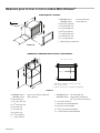
Schéma 2
Schéma 3
DIMENSIONS STANDARD D'INSTALLATION ET DÉGAGEMENTS
DIMENSIONS DE L'APPAREIL
Mesures pour le four à micro-ondes MicroDrawer
®
A
C
D
B
F
G
H
I
E
Découpe vue de face
*
Emplacement suggéré de la prise électrique
**
Bloc antibasculement
***
La base doit supporter jusqu'à 100 lb (45,4 kg)
*
**
***
A
B
C
D
E
G
H
L
O
N
J
K
L
M
I
F
A.
MD24WS (24 po) 23
7
/8
po (606 mm)
MD30WS (30 po) 30 po (762 mm)
B. 16
5
/16
po (414 mm)
C. 23
3
/8
po (594 mm)
D. 21
7
/8
po (556 mm)
E. 38
3
/8
po (974 mm)
F. 21
5
/8
po (549 mm)
G. 14
5
/8
po (371 mm)
H. 1
11
/16
po (39 mm)
I. Environ 46 po (1,168.4 mm)
A.
MD24WS (24 po) 24 po ou 27 po (610 ou 686 mm)
MD30WS (30 po) 30 po (762 mm)
B. 36 po (914 mm)
C. 23
1
/2
po (597 mm)
D. 14
5
/8
po (372 mm)
E. 4 po (102 mm)
F. 6 po (152 mm)
G. 5 po (127 mm)
H. 3
1
/2
po (89 mm)
I. 1
1
/2
po (38 mm)
j.
MD24WS (24 po) 22
1
/8
po (562 mm)
MD30WS (30 po) 23 po (584 mm) minimum
28
1
/4
po (718 mm) maximum
K. 14
13
/16
po (376 mm)
L.
7
/8
po (22 mm) chevauchement
M.
1
/2
po (13 mm) aire visible
N.
1
/16
po (2 mm) chevauchement
O. 1
7
/16
po (36 mm) chevauchement

Française 7
INSTALLATION ENCASTRÉE
Schéma 4
Les nombreuses dimensions des Schémas 2, 3 et 4 sont
des références pour la préparation de la pose du tiroir.
Ce four à micro-ondes MicroDrawer
®
peut s’installer en des-
sous de tout four mural électrique ou à gazé.
AVIS : Prévoyez toujours une longueur suffisante de cordon
d’alimentation pour que celui-ci ne soit aucunement tendu.
Vérifiez toujours les normes et le code électriques de votre
région.
Mesures pour le four à micro-ondes MicroDrawer
®
Découpe vue de facet
Tasseau****
*
Emplacement suggéré de la prise électrique
**
Bloc antibasculement
***
La base doit supporter jusqu'à 100 lb (45,4 kg)
****
Les côtés doivent être finis et prolongés jusqu'au
tasseau. Les tasseaux doivent aussi être finis,
car ils pourraient être visibles après l'installation.
(Tasseaux ne sont pas inclus avec l'appareil.)
P
P
M
K
L
O
N
*
**
A
B
C
D ***
E
G
H
I
J
F
A.
MD24WS (24 po) 27 po (686 mm)
MD30WS (30 po) 30
5
/16
po (770 mm)
B. 36 po (914 mm)
C. 23
1
/2
po (597 mm)
D. Profondeur min. de labase 21
7
/8
po (555 mm)
E. 4 po (102 mm)
F. 6 po (152 mm)
G. 5 po (127 mm)
H. 3
1
/2
po (89 mm)
I. 14
5
/8
po (371 mm)
J. 1
5
/8
po (41 mm)
K. MD24WS (24 po) 22
1
/8
po (562 mm)
MD30WS (30 po) 28
1
/4
po (718 mm)
L. MD24WS (24 po) 24
3
/16
po (614 mm)
MD30WS (30 po) 30
5
/16
po (770 mm)
M. Découpe 16
5
/8
po (422 mm)
N.
1
/2
po (13 mm) aire visible
O. Épaisseur de la base
1
/4
po (6 mm)
P. 1 po (25 mm)

Française 8
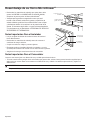
Bloc anti-basculement
ÉTAPES D’INSTALLATION NORMALE
Directives d’install ation du bloc anti-basculement
Le bloc de bois anti-basculement de 6 po sera fourni par l’installateur. Pur réduire le
risque de basculement du tiroir, le bloc anti-basculement doit être correctement installé
14 13/16 po (installation standard) ou 14 5/8 po (installation encastrée) au-dessus du
plancher sur lequel le four à micro-ondes MicroDrawer
®
sera posé. Voir Schéma 3
(installation standard) ou Schéma 4 (installation encastrée) et Schéma 5. Le bloc anti-
basculement empêche de sérieuses blessures qui pourraient survenir du déversement
de liquides chauds.
Si le tiroir est déplacé à un endroit différent, le bloc antibasculement doit l’être aussi
et réinstallé. Lorsqu’il est installé au mur, vérifier que les vis complètement à sec
pénètrent le mur et sont correctement sécurisés et dans le matériau de base underneathl le bloc soit parfaitement stable. En
fixant, faire attention que les vis ne pénètrent pas dans le câblage électrique ou la plomberie.
ATTENTION
Veiller à ce que les vis ne touchent pas au câblage ou à la plomberie dissimulés dans le mur.
AVERTISSEMENT
L'appareil peut basculer et causer des déversements et des brûlures ou d'autres blessures si le bloc antibasculement
n'est pas installé correctement.
Prise de courant
Cet appareil doit disposer d'un circuit de 120 volts, 60 Hz, 15 A (minimum) Il
est recommandé d’alimenter cet appareil par un circuit séparé.
Le four est équipé d’une fiche trois broches, mise à la terre. Il faut la branch-
er dans une prise murale correctement installée et mise à la terre. Si vous
ne possédez que des prises à deux broches, demandez à un électricien de
métier d’installer une prise murale qui convienne.
Remarque : Pour toute question à propos de l’installation électrique ou de la
mise à la terre, consulter un électricien de métier.
* Peut être installé aussi en utilisant une prise secteur dans une armoire voisine
dans les limites imposées par la longueur du cordon d’alimentation fourni avec
l’appareil.
Vérifiez toujours les normes et le code électriques de votre région.
Schéma 5
4 po
(101,6 mm)
5 po (127 mm)
Suggérée électriques
l'emplacement des orifices*
Bloc
Anti-basculement
6 po
(152,4 mm)
3 1/2 po
(89 mm)
Schéma 6
4 po
(101,6 mm)
5 po (127 mm)
Suggérée électriques
l'emplacement des orifices*
Bloc
Anti-basculement
6 po
(152,4 mm)
3 1/2 po
(89 mm)
La page charge ...
La page charge ...
La page charge ...
La page charge ...
La page charge ...
La page charge ...
La page charge ...
La page charge ...
La page charge ...
La page charge ...
La page charge ...
La page charge ...
-
 1
1
-
 2
2
-
 3
3
-
 4
4
-
 5
5
-
 6
6
-
 7
7
-
 8
8
-
 9
9
-
 10
10
-
 11
11
-
 12
12
-
 13
13
-
 14
14
-
 15
15
-
 16
16
-
 17
17
-
 18
18
-
 19
19
-
 20
20
-
 21
21
-
 22
22
-
 23
23
-
 24
24
-
 25
25
-
 26
26
-
 27
27
-
 28
28
-
 29
29
-
 30
30
-
 31
31
-
 32
32


Thermador MD30WS Guide d'installation
- Catégorie
- Micro-ondes
- Taper
- Guide d'installation
dans d''autres langues
- English: Thermador MD30WS Installation guide
- español: Thermador MD30WS Guía de instalación
Documents connexes
-
Thermador MD30WS Le manuel du propriétaire
-
-
Thermador CEM366TB Guide d'installation
-
-
-
Thermador CET366TB Guide d'installation
-
-
-
-