Faber STRTIS36WHNB Guide d'installation
- Catégorie
- Hottes
- Taper
- Guide d'installation
Ce manuel convient également à

STRTIS48WHNB
STRTIS36WHNB
Installation Instructions
Use and Care Information
Instructions d'installation
Utilisez et d'entretien
Instrucciones de instalación
Información de uso y cuidado
STRATUS NB

2
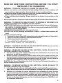
READ AND SAVE THESE INSTRUCTIONS BEFORE YOU START
INSTALLING THIS RANGEHOOD
WARNING: - TO REDUCE THE RISK OF A RANGE TOP GREASE FIRE:
a) Never leave surface units unattended at high settings. Boilovers cause smoking and
greasy spillovers that may ignite. Heat oils slowly on low or medium setting.
b)AlwaysturnhoodONwhencookingathighheatorwhenambeingfood(i.e.Crepes
Suzette, Cherries Jubilee, Peppercorn Beef Flambé).
c) Clean ventilating fans frequently. Grease should not be allowed to accumulate on fan
orlter.
d) Use proper pan size. Always use cookware appropriate for the size of the surface element.
WARNING: - TO REDUCE THE RISK OF INJURY TO PERSONS IN THE EVENT OF A
RANGE TOP GREASE FIRE, OBSERVE THE FOLLOWING*:
a)SMOTHERFLAMESwithaclose-ttinglid,cookiesheet,ormetaltray,thenturnofftheburner.
BECAREFULTOPREVENTBURNS.IftheamesdonotgooutimmediatelyEVACUATE
AND CALL THE FIRE DEPARTMENT.
b) NEVER PICK UP A FLAMING PAN - You may be burned.
c) DO NOT USE WATER, including wet dishcloths or towels - a violent steam explosion will
result.
d) Use an extinguisher ONLY if:
1. You know you have a Class ABC extinguisher, and you already know how to operate it.
2. Thereissmallandcontainedintheareawhereitstarted.
3. Theredepartmentisbeingcalled.
4. Youcanghttherewithyourbacktoanexit.
* Based on "Kitchen Firesafety Tips" published by NFPA
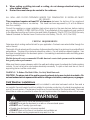
WARNING - TO REDUCE THE RISK OF FIRE OR ELECTRIC SHOCK, do not use this
fan with any solid-state speed control device.
WARNING - TO REDUCE THE RISK OF FIRE, ELECTRICAL SHOCK, OR INJURY TO
PERSONS, OBSERVE THE FOLLOWING:
1. Use this unit only in the manner intended by the manufacturer. If you have any
questions, contact the manufacturer.
2. Before servicing or cleaning unit, switch power off at service panel and lock the
service disconnecting means to prevent power from being switched on acciden-
tally. When the service disconnecting means cannot be locked, securely fasten a
prominent warning device, such as a tag, to the service panel.
CAUTION: For General Ventilating Use Only. Do Not Use To Exhaust Hazardous or
Explosive Materials and Vapors.
WARNING - TO REDUCE THE RISK OF FIRE, ELECTRICAL SHOCK, OR INJURY TO
PERSONS, OBSERVE THE FOLLOWING:
1. InstallationWorkAndElectricalWiringMustBeDoneByQualiedPerson(s)InAccor-
dance With All Applicable Codes And Standards, Including Fire-Rated Construction.
2. Sufcientairisneededforpropercombustionandexhaustingofgasesthrough
theue(chimney)offuelburningequipmenttopreventbackdrafting.Followthe
heating equipment manufacturer's guideline and safety standards such as those
publishedbytheNationalFireProtectionAssociation(NFPA), and the American
SocietyforHeating,RefrigerationandAirConditioningEngineers(ASHRAE),and
the local code authorities.

3
3. When cutting or drilling into wall or ceiling, do not damage electrical wiring and
other hidden utilities.
4. Ducted fans must always be vented to the outdoors.
ALL WALL AND FLOOR OPENINGS WHERE THE RANGEHOOD IS INSTALLED MUST
BE SEALED.
This rangehood requires at least 35" of clearance between the bottom of the rangehood
and the cooking surface or countertop. This hood has been approved by UL at this distance
from the cooktop.
Consult the cooktop or range installation instructions given by the manufacturer before making
any cutouts. MOBILE HOME INSTALLATION The installation of this rangehood must conform
to the Manufactured Home Construction and Safety Standards, Title 24 CFR, Part 3280 (formerly
Federal Standard for Mobile Home Construction and Safety, Title 24, HUD, Part 280).
• Venting system MUST terminate outside the home.
• DO NOT terminate the ductwork in an attic or other enclosed space.
• DO NOT use 4" laundry-type wall caps.
• Flexible-type ductwork is not recommended.
• DO NOT obstruct the ow of combustion and ventilation air.
• Failure to follow venting requirements may result in a re.
WARNING
!
Cold Weather installations
An additional back draft damper should be installed to minimize backward cold air ow and a
nonmetallic thermal break should be installed to minimize conduction of outside temperatures as
part of the vent system. The damper should be on the cold air side of the thermal break. The break
should be as close as possible to where the vent system enters the heated portion of the house.
VENTING REQUIREMENTS
Determine which venting method is best for your application. Ductwork can extend either through the
wall or the roof.
The length of the ductwork and the number of elbows should be kept to a minimum to provide efcient
performance. The size of the ductwork should be uniform. Do not install two elbows together. Use
duct tape to seal all joints in the ductwork system. Use caulking to seal exterior walls and ceiling space
opening around the cap.
Flexible ductwork is not recommended. Flexible ductwork creates back pressure and air turbulence
that greatly reduces performance.
Make sure there is proper clearance within the walls and ceiling space for exhaust duct before making
cutouts. Do not cut a joist or stud unless absolutely necessary. If a joist or stud must be cut, then a
supporting frame must be constructed.
WARNING - To Reduce The Risk Of Fire, Use Only Metal Ductwork.
CAUTION-Toreduceriskofreandtoproperlyexhaustair,besuretoductairoutside–Do
not vent exhaust air into spaces within walls or ceilings or into attics, crawl spaces, or garages.

4
ELECTRICAL REQUIREMENTS
A 120 volt, 60 Hz AC-only electrical supply is required on a separate 15 amp fused circuit. A time-delay
fuse or circuit breaker is recommended. The fuse must be sized per local codes in accordance with
the electrical rating of this unit as specied on the serial/rating plate located inside the unit near the eld
wiring compartment.
ELECTRICAL INSTALLATION WITH WIRING BOX
THIS UNIT MUST BE CONNECTED WITH COPPER WIRE ONLY. Wire sizes must conform to the
requirements of the National Electrical Code, ANSI/NFPA 70 - latest edition, and all local codes and
ordinances. Wire size and connections must conform with the rating of the appliance. Copies of the
standard listed above may be obtained from:
National Fire Protection Association
Batterymarch Park
Quincy, Massachusetts 02269
This appliance should be connected directly to the fused disconnect (or circuit breaker) through
exible, armored or nonmetallic sheathed copper cable. Allow some slack in the cable so the
appliance can be moved if servicing is ever necessary. A UL Listed, 1/2" conduit connector must
be provided at each end of the power supply cable (at the appliance and at the junction box).
When making the electrical connection, cut a 1 1/4" hole. A hole cut through wood must be
sanded until smooth. A hole through metal must have a grommet.
• Electrical ground is required on this rangehood.
• If cold water pipe is interrupted by plastic, nonmetallic gaskets or other materials, DO
NOT use for grounding.
• DO NOT ground to a gas pipe.
• DO NOT have a fuse in the neutral or grounding circuit. A fuse in the neutral or
grounding circuit could result in electrical shock.
• Check with a qualied electrician if you are in doubt as to whether the rangehood is
properly grounded.
• Failure to follow electrical requirements may result in a re.
WARNING
!
StateofCaliforniaProposition65Warning(USonly)
WARNING
This product contains chemicals known to the State of California to cause cancer and birth
defects or other reproductive harm.
For more information go to www.P65Warnings.ca.gov

5
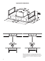
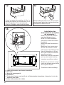
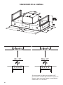
RANGEHOOD DIMENSIONS
Max. 72"Min. 35"
Recommended 60" mounting height above the
cooking surface for best performance, but can be
mounted up to 72" maximum away the cooking
surface.

6
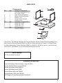
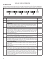
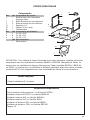
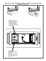
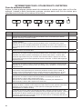
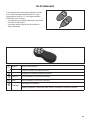
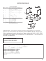
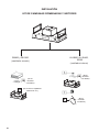
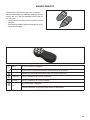
MAIN PARTS
Components
Ref. Qty. Product Components
1 1 Hood Body, complete with: Con-
trols, Lights, Filters.
2 2 UpperxingHoodBrackets
3 2 BottomxingHoodBrackets
10 1 Damperø57/8"
20 1 Flange10"(NotIncluded)
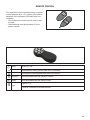
30 1 Remote Control
Ref. Qty. Installation Components
4 4 Screws1/4"x9/16"
5 8 Screws1/8"x3/8"
6 4 Screws1/8"x1/4"
Qty. Documentation
1 InstructionManual
Available Accessories
Activated Charcoal Filter Accessory - sku#; FILTER 1
Internal 600 PRO Blower sku#; IB600 kit
Internal 400 Blower sku#; IB400 kit
Internal 300 Blower sku#; IB300
Remote Blower 900 sku#; RB900
Remote Blower 1200 sku#; RB1200
10" Flange for Remote Blower sku# FLANGE10
Parts needed
- 6" Round Metal ductwork
“CAUTION - To Reduce The Risk Of Fire And Electric Shock, Install This Rangehood Only
With Remote Blower Models RB900 or RB1200 Manufactured by Faber Or Integral Blow-
ers Manufactured by Faber, Model(s) IB600 kit, IB400 kit, IB300 or generic remote blower
rated max 2,7A suitable for use with solid state speed control.
10
1
2
3
4
5
30
20
6

7
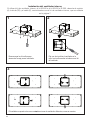
INSTALLATION
COMBINATIONS HOODS AND MOTOR KITS
RB900 and RB1200
(remote blower)
IB600 kit, IB400 kit,
IB300
(internal blower)
Version 07/11 - Page 6
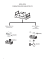
INSTALLATION
COMBINATIONS HOOD AND MOTOR KITS
CHOOSE A BLOWER FOR YOUR HOOD
After choosing the hood width and depth for your cooking
needs, next choose the type of blower appropriate for
your cooking.
NOTE: no other blower is
compatible with this hood, except for the
kits below.
# IB300 - Internal Blower Kit 300 cfm
# IB600 - Internal Blower Kit 600 cfm
# IB1200 - Internal Blower Kit 1200 cfm
# RB900 - Remote Blower Kit 900 cfm
# RB1200 - Remote Blower Kit 1200 cfm
# INLBKIT - In Line Blower Kit
(supply own in-line blower)
OPTIONAL ACCESSORIES AVAILABLE
• *Charcoal Filter
* it is highly recommended that professional style cooking always be
vented to the outside; for recirculating installations only, some ductwork is
required to exhaust the unit out of the cabinet. Replace as needed with the
same model
part # FILTER1
NOTE: The charcoal filter kit for use with the 300 / 600
cfm internal blower kit ONLY
CAUTION - To reduce risk of fire and electric shock, install this rangehood only with: Remote blower manufacturer by Faber
models RB900 and RB1200 or Integral blower manufactured by Faber models IB300 or IB600 or IB1200 or with INLBKIT and
generic in-line blower rated max 4.2 A suitable for use with solid state variable speed control
INLBKIT
Version 07/11 - Page 6
INSTALLATION
COMBINATIONS HOOD AND MOTOR KITS
CHOOSE A BLOWER FOR YOUR HOOD
After choosing the hood width and depth for your cooking
needs, next choose the type of blower appropriate for
your cooking.
NOTE: no other blower is
compatible with this hood, except for the
kits below.
# IB300 - Internal Blower Kit 300 cfm
# IB600 - Internal Blower Kit 600 cfm
# IB1200 - Internal Blower Kit 1200 cfm
# RB900 - Remote Blower Kit 900 cfm
# RB1200 - Remote Blower Kit 1200 cfm
# INLBKIT - In Line Blower Kit
(supply own in-line blower)
OPTIONAL ACCESSORIES AVAILABLE
• *Charcoal Filter
* it is highly recommended that professional style cooking always be
vented to the outside; for recirculating installations only, some ductwork is
required to exhaust the unit out of the cabinet. Replace as needed with the
same model
part # FILTER1
NOTE: The charcoal filter kit for use with the 300 / 600
cfm internal blower kit ONLY
CAUTION - To reduce risk of fire and electric shock, install this rangehood only with: Remote blower manufacturer by Faber
models RB900 and RB1200 or Integral blower manufactured by Faber models IB300 or IB600 or IB1200 or with INLBKIT and
generic in-line blower rated max 4.2 A suitable for use with solid state variable speed control
INLBKIT
1B
1D
2B
E
(Not needed
with Stratus)
(Not needed
with Stratus)
(Not needed
with Stratus)
(Not used with 10"
External Blowers)

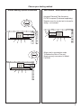
8
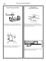
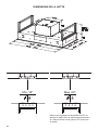
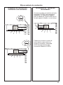
Choose your ducting method
Non Ducted - Recirculation OptionDucted Venting Options Installation
Activated Charcoal Filter Accessory
FILTER1 required (Purchased separately).
Register cover for air duct exit is shown for
design - not included.
When used in recirculation mode,
To Reduce the Risk of Fire and
Shock use only conversion kit Model
FILTER1
6 "
6 "

9
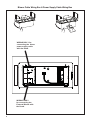
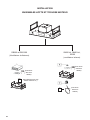
Blower Cable Wiring Box & Power Supply Cable Wiring Box
WIRING BOX 1 for
connecting the Home
power supply cable
with the Hood.
WIRING BOX 2
for connecting the
External Blower with
the Hood.

10
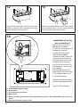
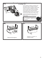
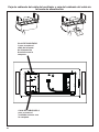
1
Put a thick, protective covering over cooktop
to protect from damage or dirt.
Determine and clearly mark with a pencil on the
ceiling where the rangehood will be installed.
Determine and make necessary cuts for the
ductwork. The duct opening is shown on the
mounting template.
Install ductwork before mounting the hood.
Determine the proper location for the Power
Supply Cable as indicated on the template.
Use a 1 1/4" Drill Bit to make this hole. Run
the Power Supply Cable. Use caulking to seal
around the hole.
A knockout for threading through the Power
Supply from the ceiling is located on the top
of the frame. Do not connect the Power Cable
to the Wiring Box or power up the hood at this
time. Run enough power cable from the ceiling
to reach the wiring box on the hood.
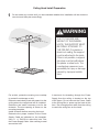
Do not make any cutouts until you have decided whether this installation will be ducted or
non-duct and then plan accordingly.
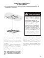
DUE TO THE SIZE AND
WEIGHT OF THIS RANGE-
HOOD, THE SUPPORT MUST
BE FIRMLY ATTACHED TO
THE CEILING. For plaster or
sheet rock ceiling, the support
must be attached to the joists.
If this is not possible, a support
structure must be built behind
the plaster or sheet rock. The
manufacturer assumes no re-
sponsibility for injury or damage
caused by improper installa-
tions.
WARNING
!
Ceiling Hood Install Preparation

11
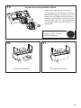
2
3
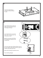
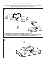
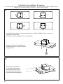
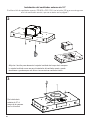
Unfastenthe4screwstodismounttheBlowerBoxfromthehoodbodyandtosavescrews.
TheBlowerBoxisnotusedforRemoteBlowerinstallationandcanbediscardedorsavedforfutureuseif
convertedtoInternalBlower.
Fixthe10"
ange(#FLANGE10
-purchasedseparately)with
the4screwsprovidedin
thehardwarebagasshown.
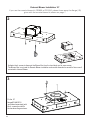
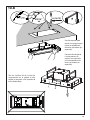
External Blower Installation 10"
lf you use the remote blower kit, RB900 or RB1200, please throw away the ange (1B)
given with the remote blower kit,shown on page 7.

12
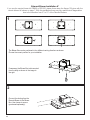
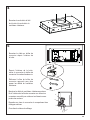
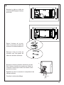
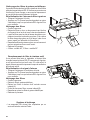
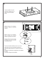
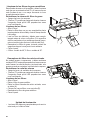
4
ConnecttheHoodbodyair
outletwiththeRemoteBlower
airoutlet.
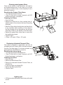
5
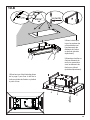
FromInsidetheHood,removethe
Cover from the wiring box 2 by
removingtwoscrews.
BreakthecorrectholeintheWiring
Boxforpassingthecablesfromthe
remoteblower.
FromInsidetheHoodconnectthe
CabletotheWiringBOXasshown
intheimagetotheright.
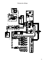
ConnectthecablefromtheRemoteBlowerwiththe
twowiresinsidetheWiringBoxbytwist-on type wire
connectorandmatchingthecolor
Replacetheeldwiringcompartmentcover.
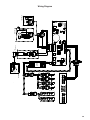
ChecktheWiringDiagram.
A
E
D
C
B

13
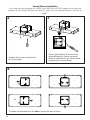
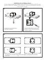
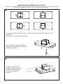
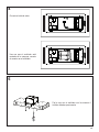
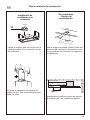
1
IfnecessarytheBlowerBoxisdismounted
fromthebodyasshownintheimageto
the right.
TheBlowerBoxcanbepositionedinfourdifferentventingdirectionsasshown.
Choosethecorrectpositionforyourinstallation.
Connecttheductingfromthe
Remote Blower to the Blower
Box.Useclampstosecure
(purchasedseparately).
2
External Blower Installation 6"
lf you use the remote blower kit, RB900 or RB1200, please throw away the ange (1B) given with the
remote blower kit1shown on page 7. With this installation there may be a performance degradation
due to the transition from 6" to 10" of the Remote Blowers.

14
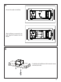
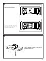
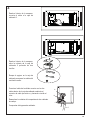
3
Frominsidethehood,removethe
cover from the Wiring Box 2 by
removingthetwoscrews.
Breakthehole intheWiringBox
for passing the cables from the
remoteblower.
FromInsidetheHoodconnectthe
cabletotheWiringBOX2.
ConnectthecablefromtheRemoteBlowerwiththetwo
wireinsidetheWiringBoxbytwist-on type wire connec-
torandmatchingthecolor.
Replacetheeldwiringcompartmentcover.
ChecktheWiringDiagram.
A
E
D
C
B

15
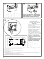
2
4
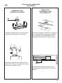
Unfastenthe4screwstodismountthe
Boxfortheblower.
Theblowercanbepositionedinfourdifferentventingdirectionsasshown.
3
PositionInternalBlowerasshownintothe
removedBlowerBox.SecuretheInternal
BlowerintheBlowerBoxwiththetwoscrews
providedwiththeInternalBlower.
Internal Blower Installation
lf you use the internal blower kit, IB600 kit or IB400 kit or IB300, please throw away the
damper (A), the ange (2B) and the cable (E), given with the internal blower kit, shown on
page 7.

16
5
FixtheBoxwiththeBlowerwiththesame4screws
removedpreviously.
AftertheBlowerismountedinthe
hoodplugtheConnectorintothe
Blower
6
ConnectthecabletotheMotor.

17
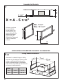
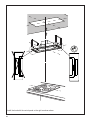
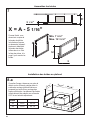
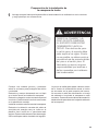
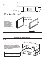
Assemble the Brackets
$
PP
; $PP
;
%[
5
X = A - 5 1/16"
5 1/16"
7
Asshown,youhave
toaccommodate
for the height of the
hoodbodyintoyour
spaceoverhead.After
determiningbracket
heightusethe#5
Screws from Component
Page6toassemble
brackets.
15
3/4
”
33
1/16
” - 44 7/8”
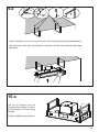
Seebelowforadetailedimageondrilling
theholesontothefasteningsurface(inside
ceilingorsoft)thatwillthenbeusedto
mountthebracketxtures.Thefasteners
usedmustbecompatiblewiththe5/16"hole
andarepurchasedseparately.
Ceiling Bracket Installation
Hood
36" 153/4" 33 1/16"
48" 153/4" 44 7/8"
8.a
Min. 7 5/16"
Max. 12 13/16"
HOOD INSTALLATION BEFORE THE SOFFIT IS COMPLETED

18
´
[
[
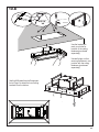
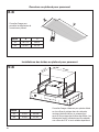
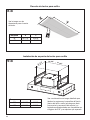
Usethebracketstomarkyourholesforlocationoftheceilingfasteners(purchasedseparately).
Usewallplugsorothersecuringhardwareinconjunctionwiththeceilingfasteners(purchased
separately).
9.a
´
[
[
10.a
C (M6x15)
Use the #4 Screws from the
ComponentlistonPage6toattach
thehoodbodytothehoodceiling
brackets.
Accessisneededinthespaceabove.

19
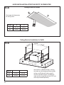
CeilingCutoutforSoft
8.b
Seeimagewithdimensions
forceilingcutout.
Ø 5/16”
x4
x4
475
878
15
3/4
”
23
5/8
” - 31
5/8
”
18
11/16
” - 26
9/16
”
23
5/8” - 31
5/8
”
X
Y
9.b
Seebelowforadetailedimageondrilling
theholesontothefasteningsurface(inside
ceilingorsoft)thatwillthenbeusedto
mountthebracketxtures.Thefasteners
usedmustbecompatiblewiththe5/16"hole
andarepurchasedseparately.
Hood
36" 153/4" 235/8"
48" 153/4" 31 5/8"
CeilingBracketInstallationforSoft
Hood X Y
36" 18 11/16" 34 9/16"
48" 269/16" 463/8"
´
´
´
HOOD INSTALLATION AFTER THE SOFFIT IS COMPLETED

20
Usethebracketsto
markyourholesfor
locationoftheceiling
fasteners(purchased
separately).
Usewallplugsorother
securinghardwareincon-
junctionwiththeceiling
fasteners(purchased
separately).
Usethe#4ScrewsfromtheComponent
listonPage6toattachthehoodceiling
bracketsfromthebottom.
10.b
Ø 8 mm
A (5x70)
x4
x4
475
878
400
600 -
803
475 - 675
878 - 1178
5/16"
1 2
C (M6x15)
3
La page charge ...
La page charge ...
La page charge ...
La page charge ...
La page charge ...
La page charge ...
La page charge ...
La page charge ...
La page charge ...
La page charge ...
La page charge ...
La page charge ...
La page charge ...
La page charge ...
La page charge ...
La page charge ...
La page charge ...
La page charge ...
La page charge ...
La page charge ...
La page charge ...
La page charge ...
La page charge ...
La page charge ...
La page charge ...
La page charge ...
La page charge ...
La page charge ...
La page charge ...
La page charge ...
La page charge ...
La page charge ...
La page charge ...
La page charge ...
La page charge ...
La page charge ...
La page charge ...
La page charge ...
La page charge ...
La page charge ...
La page charge ...
La page charge ...
La page charge ...
La page charge ...
La page charge ...
La page charge ...
La page charge ...
La page charge ...
La page charge ...
La page charge ...
La page charge ...
La page charge ...
La page charge ...
La page charge ...
La page charge ...
La page charge ...
La page charge ...
La page charge ...
La page charge ...
La page charge ...
La page charge ...
La page charge ...
La page charge ...
La page charge ...
La page charge ...
La page charge ...
La page charge ...
La page charge ...
-
 1
1
-
 2
2
-
 3
3
-
 4
4
-
 5
5
-
 6
6
-
 7
7
-
 8
8
-
 9
9
-
 10
10
-
 11
11
-
 12
12
-
 13
13
-
 14
14
-
 15
15
-
 16
16
-
 17
17
-
 18
18
-
 19
19
-
 20
20
-
 21
21
-
 22
22
-
 23
23
-
 24
24
-
 25
25
-
 26
26
-
 27
27
-
 28
28
-
 29
29
-
 30
30
-
 31
31
-
 32
32
-
 33
33
-
 34
34
-
 35
35
-
 36
36
-
 37
37
-
 38
38
-
 39
39
-
 40
40
-
 41
41
-
 42
42
-
 43
43
-
 44
44
-
 45
45
-
 46
46
-
 47
47
-
 48
48
-
 49
49
-
 50
50
-
 51
51
-
 52
52
-
 53
53
-
 54
54
-
 55
55
-
 56
56
-
 57
57
-
 58
58
-
 59
59
-
 60
60
-
 61
61
-
 62
62
-
 63
63
-
 64
64
-
 65
65
-
 66
66
-
 67
67
-
 68
68
-
 69
69
-
 70
70
-
 71
71
-
 72
72
-
 73
73
-
 74
74
-
 75
75
-
 76
76
-
 77
77
-
 78
78
-
 79
79
-
 80
80
-
 81
81
-
 82
82
-
 83
83
-
 84
84
-
 85
85
-
 86
86
-
 87
87
-
 88
88


Faber STRTIS36WHNB Guide d'installation
- Catégorie
- Hottes
- Taper
- Guide d'installation
- Ce manuel convient également à
dans d''autres langues
- English: Faber STRTIS36WHNB Installation guide
- español: Faber STRTIS36WHNB Guía de instalación
Documents connexes
-
Faber High-Light 36 WHNB Guide d'installation
-
-
Faber Stratus 48 SS Guide d'installation
-
-
-
-
-
-
-
Faber INCA PRO PLUS Guide d'installation