
BIGASSFANS.COM
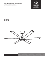
es6
EXCEPTIONALLY
ENGINEERED
READ AND SAVE THESE INSTRUCTIONS
À LIRE ET À CONSERVER EN LIEU SÛR
LEA Y CONSERVE ESTAS INSTRUCCIONES

REV. A | 08/30/2021
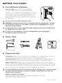
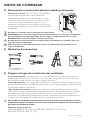
☑ Prepare Fan Site
Outlet Box: Make sure your outlet box is suitable for fan support. If there is not an
outlet box at the fan location, install one on a ceiling joist or beam.
Concrete Ceiling: Install an anchor hook for the safety cable if required by your
local building and safety code. See the following page for installation details.
Wood Ceiling Joist: Attach the mounting bracket directly to the joist using two
wood screws (not supplied). Recommended: Corrosion-resistant 12-11 x 45 mm hex
head timber screws with seal. If required by local code, mount or embed an outlet
box into the joist. The outlet box must be suitable for fan support.
The mounting/fixing means for attachment to the ceiling such as hooks or other
devices shall be fixed with a sucient strength to withstand four times the
weight of the ceiling fan.
Models and Maximum Weight:
MK-ES62-052306: 25 lb (11.3 kg), MK-ES62-062306: 27 lb (12.1 kg),
MK-ES62-072306: 29 lb (13.2 kg)
Do not use the fan with a dimmer switch.
WARNING: Installation must be in accordance with the requirements set forth
by the National Electrical Code (NEC, United States), ANSI/NFPA 70, and all
national and local codes.
The ground wire must be connected to the supply ground and its length must
be longer than the safety cable.
A means for disconnection must be incorporated in the fixed wiring in
accordance with the wiring rules.
BEFORE YOU START
☑ Turn o Power at Breaker
Input Voltage: 100–277 VAC, 1 Φ, 50/60 Hz
Do not connect the fan to a damaged power
source. Do not attempt to resolve electrical failures
on your own. Contact a licensed electrician if you
are uncomfortable performing electrical work. A
licensed electrician must install the fan if required
by local code.
☑ Gather Tools
Provided with fan

© 2021 DELTA T LLC Ι ALL RIGHTS RESERVED.
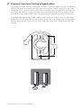
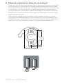
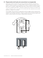
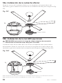
☑ Prepare Concrete Ceiling (if applicable)
Drill three Ø 8 mm holes in the pattern shown. The hole depth should not exceed
46mm. Remove any dust from the holes. Insert three anchor bolts into the holes.
Strike the heads of the anchor bolts with a hammer, ensuring the bolt sleeves are
fl ush with the ceiling surface. Position the mounting bracket on the anchor bolts.
Ensure all three anchor bolts are fully tightened to expand and lock the anchors.
If required by local building and safety codes, install an anchor hook for the safety
cable. Drill an Ø 8 mm hole for the anchor hook. The hole depth should not exceed
46 mm. Remove any dust from the hole, and then insert the anchor hook and fully
tighten.
Ø 8 mm
45 mm 43 mm
112 mm
46 mm max
46 mm max

REV. A | 08/30/2021
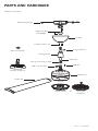
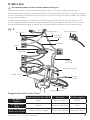
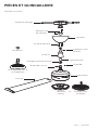
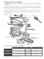
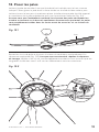
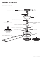
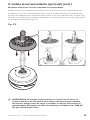
PARTS AND HARDWARE
EMI filter not shown.
Mounting Bracket
Lower Cover
Mounting Ball
and Wedge
Canopy Screws (4)
Canopy
6 mm Steel Pin
Downrod
Wiring Cover
M6 x 32 mm Bolt M6 Nut
Airfoils (6)
Wire Connectors
Motor Unit
Wiring and Safety Cable
Uplight (Optional)
LED Light
(Optional)
or

© 2021 DELTA T LLC Ι ALL RIGHTS RESERVED. 1
INSTALLATION
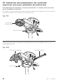
1. Install downrod
Align holes on downrod with holes on motor bracket. Secure downrod with the
M6x32mm bolt and M6 nut (Fig. 1.1). If you are installing the optional uplight, make sure
the downrod wiring harness and the motor unit wiring harness are on opposite sides of
the downrod. This will make the harnesses easier to connect to the uplight.
Fig. 1.1
M6 x 32 mm Bolt
M6 Nut
If you are NOT installing the uplight, connect downrod wiring harness to motor unit
wiring harness (Fig. 1.2). If you are installing the uplight, do not connect the downrod
wiring harness.
Fig. 1.2
Downrod Wiring Harness
(connect only if NOT
installing uplight)
Motor Unit
Wiring Harness
Downrod Wiring
Harness
Motor Unit Wiring
Harness

REV. A | 08/30/20212
2. Install lower safety cable and ground wire
Install safety cable and ground wire lugs with unpainted screws and lock washers
(Fig.2.1).
Fig. 2.1
Ground Wire (Green)
Safety Cable
Lock
Washer
Screw
3. Install uplight (optional)
Skip this step if you are not installing the uplight.
Make sure wiring harnesses are as close to downrod as possible so that they do not
interfere with uplight installation (Fig. 3.1).
Fig. 3.1

© 2021 DELTA T LLC Ι ALL RIGHTS RESERVED. 3
3. Install uplight (optional) (cont.)
Skip this step if you are not installing the uplight.
Align rectangular cutouts in center of uplight with bolts on downrod. Make sure uplight
wiring harness and motor unit wiring harness are on opposite sides of downrod. This will
make the harnesses easier to connect. Slide uplight down the downrod, resting it on the
fan hub (Fig. 3.2).
Fig. 3.2
WARNING: Skin or eye damage may result from directly viewing ultraviolet
light produced by the lamp in this apparatus. Always disconnect power before
relamping or servicing. Replace ultraviolet LEDs with Model No. 1050-45-50,
manufactured by Big Ass Fans.

REV. A | 08/30/20214
3. Install uplight (optional) (cont.)
Skip this step if you are not installing the uplight.
Tighten the two set screws at top of uplight. Connect uplight wiring harness to motor
unit wiring harness. Connect downrod wiring harness to receptacle on uplight (Fig. 3.3).
Fig. 3.3
4. Reduce slack
Make sure all hardware is secure, and then gently tug cables at top of downrod to
reduce slack (Fig. 4).
Fig. 4
Uplight Wiring
Harness to Motor
Unit Wiring Harness
Downrod Wiring
Harness to Uplight
Receptacle

© 2021 DELTA T LLC Ι ALL RIGHTS RESERVED. 5
5. Position wiring cover and canopy
Slide wiring cover down downrod, resting it on the fan hub or uplight. Make sure
no wires are visible between the cover and fan hub or uplight. Slide canopy down
downrod, resting it on the wiring cover (Fig. 5).
Fig. 5
Canopy
Wiring Cover
6. Install mounting ball
Slide mounting ball over downrod (Fig. 6.1).
Insert 6 mm steel pin into hole at top of downrod, and then slide the mounting ball
upward, seating the steel pin in the inner slots (Fig. 6.2).
Insert wedge into mounting ball and secure with screw. Tighten screw enough to
prevent movement between the mounting ball and downrod, but do not over-tighten
(Fig. 6.3).
Fig. 6.1
Mounting Mounting
BallBall
Downrod
6 mm Steel Pin
Screw
Wedge
Fig. 6.2 Fig. 6.3

REV. A | 08/30/20216
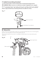
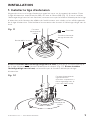
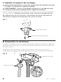
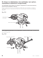
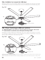
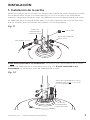
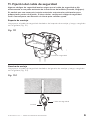
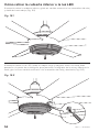
7. Install mounting bracket
Disconnect power to fan location before installing mounting bracket.
WARNING: Mount only to an outlet box marked acceptable for fan support.
Secure mounting bracket to mounting structure with suitable hardware (not supplied)
(Fig. 7). Outlet box shown. Your mounting structure may diff er from the illustration.
Power supply omitted from mounting bracket illustration for clarity.
Fig. 7
Suitable Mounting Hardware
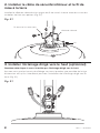
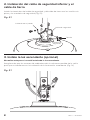
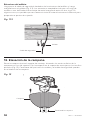
8. Hang fan
Raise fan to mounting bracket. Align rib in mounting bracket with slot in mounting ball,
position mounting ball, and let fan hang freely (Fig. 8).
Gently twist downrod to ensure it is properly seated and will not move during fan
operation.
Fig. 8
Mounting Ball
Mounting Bracket
Mounting Bracket

© 2021 DELTA T LLC Ι ALL RIGHTS RESERVED. 7
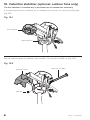
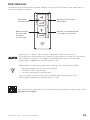
9. Wire fan
Disconnect power to fan location before wiring fan.
Wire fan as shown using the wire connectors (Fig. 9). Attach green ground wire to
mounting bracket with the unpainted screw. Connect wiring harness from power supply
to wiring harness from downrod, making sure that the wiring and safety cable are routed
in the same direction.
Carefully tuck wiring into outlet box or building structure. Ensure wire connectors are
turned upward and that wires are spread apart with grounded conductors on one side
of the outlet box/mounting structure and ungrounded conductors on the other side.
Fig. 9
North America 100–120 V Australia All other regions
AC Hot/L1
Brown Black Brown or Red Brown
AC Neutral/L2
Blue White Black or Light Blue Blue
PE/Earth Ground
Green with Yellow Green or Bare Copper Green with Yellow Green with Yellow
Supply Power Wire Color Chart
AC HOT/L1
BROWN
AC NEUTRAL/
L2
PE/EARTH
GROUND
BLUE
GREEN &
YELLOW
EMI Filter
Power Supply
Wiring Harnesses
Mounting Bracket
Safety
Cable
RED Wire Connector

REV. A | 08/30/20218
10. Install fan stabilizer (optional, outdoor fans only)
The fan stabilizer is included only if purchased as an outdoor fan accessory.
If you purchased the fan stabilizer kit, fi t stabilizer into notches on top of mounting ball
(Fig. 10.1).
Fig. 10.1
Mounting Ball
Fan Stabilizer
Secure stabilizer plate to stabilizer with the M6 x 70 mm bolt and M6 nut (Fig. 10.2).
Fig. 10.2
M6 Nut
Stabilizer Plate M6 x 70 mm Bolt

© 2021 DELTA T LLC Ι ALL RIGHTS RESERVED. 9
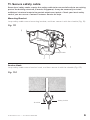
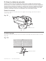
11. Secure safety cable
Some local safety codes require the safety cable to be secured directly to an existing
part of the building structure (Canada, Singapore). It may be necessary to install
additional structural material to provide attachment points. Check your local safety
code if you are unsure. Contact Customer Service for help.
Mounting Bracket
Loop safety cable around mounting bracket, and then secure it with the shackle (Fig. 11.1).
Fig. 11.1
Shackle
Safety Cable
Anchor Hook
Loop safety cable around anchor hook, and then secure it with the shackle (Fig. 11.2).
Fig. 11.2
Safety Cable
Shackle

REV. A | 08/30/202110
12. Raise canopy
Raise canopy to mounting bracket, aligning the four holes on the canopy with the holes
on the bracket. Secure canopy to mounting bracket with the painted screws (Fig. 12).
Make sure all wires and the safety cable are tucked in the canopy.
Fig. 12
Canopy
Canopy Screw
Building Structure
Loop safety cable around building structure, and then secure it with the shackle (Fig.
11.3). Acceptable building structures include a wooden beam or a metal mounting brace
secured between two beams. In some cases it may be necessary to install additional
structural material to provide attachment points.
Fig. 11.3
Safety Cable
Shackle

© 2021 DELTA T LLC Ι ALL RIGHTS RESERVED. 11
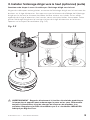
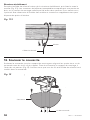
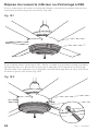
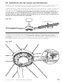
13. Install airfoils
Tilt airfoil so that tip is angled upward as shown. Slide airfoil into slot on side of motor
unit, and then tilt downward into place. Install each airfoil on opposite side of fan from
previous airfoil to prevent fan from tilting (Fig. 13.1). Make sure numbered sticker on
each airfoil matches corresponding slot number on bottom of fan. Ensure all airfoils
are fully seated in slots before tightening screws on bottom of fan.
Fig. 13.1
Tighten the six airfoil screws on bottom of fan according to numbered sequence
(Fig. 13.2). When fi nished, repeat tightening sequence. Verify all six screws are fully
tightened by making sure the tabs next to holes 1 and 5 are fl ush with the openings.
Fig. 13.2
Airfoil

REV. A | 08/30/202112
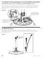
14a. Install lower cover
Align slots on lower cover with tabs on bottom of fan and twist cover clockwise to lock
(Fig. 14.1).
Fig. 14.1
Lower Cover
LED Light
14b. Install LED light (optional)
CAUTION: To reduce the risk of electric shock, disconnect power to fan before
installing LED light.
Plug LED light wiring harness into receptacle on bottom of fan. Align slots on light with
tabs on bottom of fan and twist light clockwise to lock (Fig. 14.2).
Fig. 14.2
Use only with light kits marked “Suitable for Use in Wet Locations.”
Use only light kit model 009786. Light Kit Weight: 2.2 lb (998 g)

© 2021 DELTA T LLC Ι ALL RIGHTS RESERVED. 13
For operation, maintenance, and troubleshooting information, visit bigassfans.com/support
Congratulations!
Installation is now complete. Turn on power and test your fan using the remote control.
Fan On/O Adjust Fan Speed
Light(s) On/O
(if included)
Adjust Light Brightness
(if included)
Press Auto to enable motion sensing and automatic fan speed adjustment
as room conditions change. To adjust your Auto preferences, download the
Big Ass Fans mobile app.
Press and hold to change control modes:
• Uplight only
• LED light only
• Both lights simultaneously
To change the color of the uplight’s LEDs, download the Big Ass Fans
mobile app.

REV. A | 08/30/202114
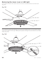
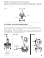
If you need to remove the LED light, use a long, thin object such as a small allen wrench
or pen tip to press tab on light. While pressing tab, twist light counterclockwise and slide
down (Fig. 15.2).
Fig. 15.2
Removing the lower cover or LED light
If you need to remove the lower cover, twist cover counterclockwise and slide down
(Fig. 15.1).
Fig. 15.1

© 2021 DELTA T LLC Ι ALL RIGHTS RESERVED. 15
MAINTENANCE AND CLEANING
WARNING: Risk of fire, electric shock, or injury to persons during cleaning and
user maintenance. Disconnect the appliance from the power supply before
servicing.
WARNING: Skin or eye damage may result from directly viewing ultraviolet
light produced by the lamp in this apparatus. Always disconnect power before
relamping or servicing.
Please take a few moments each year to perform the following preventative
maintenance procedures on your fan to ensure its safe and ecient operation.
Checking the safety cable
Check that the safety cable is properly installed by removing the canopy screws, sliding
the canopy down the downrod, and examining the safety cable and hardware.
Checking the hardware
Make sure the mounting hardware and the screws securing the airfoils to the fan hub
are securely fastened. Tighten the six airfoil screws on the bottom of the fan according
to the numbered sequence. When finished, repeat the tightening sequence.
Checking the wiring
Make sure the wire connectors are secure and the ground wires are securely
connected.
Cleaning the airfoils
Dust the airfoils regularly. If the fan becomes dirty, clean it with a damp cloth and
ordinary soap and water. Do not use solvents, gasoline, or any other chemical cleaners!
These may cause surface distortion and damage to the fan.
Cleaning the uplight
Clean the LEDs periodically to ensure optimal performance. Use a compressed air
duster to remove dust and debris from the LEDs. Do not touch the LEDs while cleaning.
Hold the duster can upright when using.

La page charge ...
La page charge ...
La page charge ...
La page charge ...
La page charge ...
La page charge ...
La page charge ...
La page charge ...
La page charge ...
La page charge ...
La page charge ...
La page charge ...
La page charge ...
La page charge ...
La page charge ...
La page charge ...
La page charge ...
La page charge ...
La page charge ...
La page charge ...
La page charge ...
La page charge ...
La page charge ...
La page charge ...
La page charge ...
La page charge ...
La page charge ...
La page charge ...
La page charge ...
La page charge ...
La page charge ...
La page charge ...
La page charge ...
La page charge ...
La page charge ...
La page charge ...
La page charge ...
La page charge ...
La page charge ...
La page charge ...
La page charge ...
La page charge ...
La page charge ...
La page charge ...
-
 1
1
-
 2
2
-
 3
3
-
 4
4
-
 5
5
-
 6
6
-
 7
7
-
 8
8
-
 9
9
-
 10
10
-
 11
11
-
 12
12
-
 13
13
-
 14
14
-
 15
15
-
 16
16
-
 17
17
-
 18
18
-
 19
19
-
 20
20
-
 21
21
-
 22
22
-
 23
23
-
 24
24
-
 25
25
-
 26
26
-
 27
27
-
 28
28
-
 29
29
-
 30
30
-
 31
31
-
 32
32
-
 33
33
-
 34
34
-
 35
35
-
 36
36
-
 37
37
-
 38
38
-
 39
39
-
 40
40
-
 41
41
-
 42
42
-
 43
43
-
 44
44
-
 45
45
-
 46
46
-
 47
47
-
 48
48
-
 49
49
-
 50
50
-
 51
51
-
 52
52
-
 53
53
-
 54
54
-
 55
55
-
 56
56
-
 57
57
-
 58
58
-
 59
59
-
 60
60
-
 61
61
-
 62
62
-
 63
63
-
 64
64


