
INSTALLATION XON69 / XON69E
Doc. # DR167-1 / 21-09-2021 www.rubi.ca - 1.888.988.RUBI (7824)
02
Prévoyez une distance appropriée entre la
plaque d'installation et le mur fini. Un ajuste-
ment de 12mm [1/2''] est possible.
Allow an appropriate distance between the
installation plate and the finished wall. A 12mm
[1/2''] adjustement is possible.
ÉTAPES / STEPS
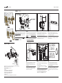
PIÈCES / PARTS
Vérifiez que toutes les pièces de votre mitigeur soient dans l'emballage.
Make sure you have all the parts in hand.
LISTE DES PIÈCES / PARTS LIST
01 Rough
02 Cartouche température / Temperature cartridge
03 Cartouches selectrices / Selector cartridges
04 Noix de serrage pour 03 / tightening nuts for 03
05 Bague de température / temperature lock
06 Bouchon / Cap
07 Sortie d'eau
(seulement avec XON69E)
/ Water oulet
(only in XON69E)
01B
La sortie 03 est une sortie libre (à alimentation
continue). Si vous l'utilisez pour installer un
accessoire, prévoyez l'ajout d'une valve d'arrêt
au circuit.
The outlet 03 is a free outlet (continuous feed).
If you use it to install an accessory, make sure
you add a stop valve to the line plan.
05
Raccordez les entrées d'eau chaude et d'eau
froide et effectuez les branchements des diffé-
rents accessoires.
Si vous installez la valve avec sortie d'eau
intègrée (XRA69), referez-vous au doc.DR169 à
cette étape.
Connect the hot and cold water inlets and make
the connections for the various accessories.
If you install a mixer with inetgrated water outlet
(XRA69), refer to doc.DR169 at this stage.
04
Fixez la plaque d'installation sur le montant
horizontal. Assurez-vous que celle-ci soit
droite. Utilisez un niveau si nécéssaire.
Vis
non-incluses.
Secure the installation plate to the horizontal
mount. Make sure it is straight. Use a level if
needed.
Screws not included.
01A
Si vous n'avez pas besoin des trois sorties d'eau,
utilisez les sorties 01 et 02. Assurez-vous que le
bouchon installé à la sortie 03 soit bien serré
et étanche.
If you only need two water outlets, use the
outlets 01 and 02. Make sure the cap installed
on the outlet 03 is watertight.
EAU CHAUDE
HOT WATER
EAU FROIDE
COLD WATER
SORTIE 01
OUTLET 01 SORTIE 02
OUTLET 02
SORTIE 03 - LIBRE AV. BOUCHON
OUTLET 03 - FREE WITH CAP
PLAQUE D’INSTALLATION
INSTALLATION PLATE
02
01
05
03
06
XON69
XON69E
07
Optionnel
Optional
VAR. 19 - 32 mm
[3/4’’ - 1 1/4’’]
03
Préparez une traverse horizontale en 2 x 3.
Assurez-vous que cette traverse soit bien droite,
votre installation en dépend.
Prepare a horizontal crosspiece with 2 x 3's.
Make sure this piece is straight as your installa-
tion depends on it.
06
Purgez votre valve. Gardez les bouchons en
place et ouvrez l'eau, laissez couler 15 à 20
secondes. Assurez-vous que tous les branche-
ments soient étanches.
Purge your valve. Keep the cartridge caps in place
and open your water, let water flow for 15 to 20
seconds. Make sure all your connections are water
tight.
OUVRIR
L'EAU
OPEN
WATER
04

INSTALLATION XON69 / XON69E
Doc. # DR167-1 / 21-09-2021 www.rubi.ca - 1.888.988.RUBI (7824)
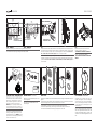
ATTENTION / WARNING
L'utilisation avec une substance autre que l'eau
pourrait endommager et causer un bris d’équipe-
ment. Évitez tout contact, ainsi que l’entreposage,
avec les produits ménagers, chimiques et corrosifs.
Ne pas nettoyer avec des produits rugueux ou des
matières abrasives.
Using a substance other than water could damage
and cause equipment failure. Avoid contact and
storage, with household products, chemicals and
corrosive. Do not clean with rough or abrasive mate-
rials.
07A - XON69
Fermez le mur. Prévoyez une ouverture selon le gabarit de découpe fourni.
Close the wall. Provide an opening according to the template provided.
08
À l'aide d'un tournevis à tête plate, tournez les boulons afin que la face de celui-ci arrive vis-à-vis
votre mur fini. Pour un ajustement optimal : Effectuez au maximum 2 rotations sur chaque boulon
puis répetez la séquence jusqu'à ce que les 3 arrivent à égalité avec votre mur fini. (EX : vis #1= 2
tours ; vis #2 = 2 tours ; vis #3 = 2 tours ; répétez). Utilisez un niveau pour valider.
Close the wall. Provide an opening according to the template provided. For optimal adjustement : Perform
a maximum of 2 rotations on each bolt then repeat the sequence until the front of the three bolts reach
your finished wall. (EX : screw #1= 2 full turns ; screw #2 = 2 full turns ; screw #3 = 2 full turns ; repeat). Use
a level to validate.
09
Retirez les 3 bouchons sur les trous de car-
touches et installez les cartouches.
*NE PAS METTRE SOUS PRESSION SANS LES NOIX ET VIS*
Remove cap and install the 3 cartridges.
*DO NOT PUT UNDER PRESSURE WITHOUT NUTS AND SCREWS
INSTALLED*
5 deg
MUR FINI / FINISHED WALL
1
3
2
MAX. 2 tours à la fois
MAX. 2 turns at a time
178 mm
[7’’]
76 mm
[3’’]
ALLIGNER LA DÉCOUPE SOUS LES
VALVES ANTI-RETOUR
ALLIGN CUTOUT WITH CHECK VALVES
1
2
3
CARTOUCHE DE TEMPÉRATURE
TEMPERATURE CARTRIDGE
Desserrez la vis de réglage dans le corps de la
valve permettant l'alignement de la cartouche.
Positionnez la cartouche puis serrez la vis.
ATTENTION La pièce de plastique doit être repla-
cée en alignant le bout de l'arc à environ 5˚. Le
bouton-pression doit être au haut de la poignée.
Loosen the set screw in the main valve body
allowing the cartridge alignment.place the car-
tridge and tighten the screw. WARNING The plastic
part should be assembled aligning the half-ring
end at 5˚. Push-button on top.
07B - XON69E
216 mm
[8 1/2’’]
76 mm
[3’’]
ALLIGNER LA DÉCOUPE SOUS LES
VALVES ANTI-RETOUR
ALLIGN CUTOUT WITH CHECK VALVES
GARNITURES / TRIMS
Référez vous au document DR168 pour l'instal-
lation des garnitures.
Please refer to document DR168 for the trim
installation guide.
DR168
VERTICAL
Pour faire une installation à la verticale il faudra repositionner la bague de température ainsi que la
poignée.
1. Retirez la bague de température, effectuez unquart de tour en sens anti-horaire puis replacez la.
2. Replacez la poignée avec le bouton vers le haut et serrez la vis allen.
To install vertically, you will need to reposition the temperature ring and the handle.
1. Remove the temperature ring, turn it 90 degrees counterclockwise and put it back in place.
2. Re-instal the handle with the button facing up and tighten the allen screw.
1.
2.
90˚
-
 1
1
-
 2
2


Rubi RON851 Guide d'installation
- Catégorie
- Articles sanitaires
- Taper
- Guide d'installation
dans d''autres langues
- English: Rubi RON851 Installation guide
Documents connexes
-
Rubi XSU10.5T Guide d'installation
-
-
-
-
-
-
-
-
-