CARLO GAVAZZI EM24DINAV53XW1IX Manuel utilisateur
- Taper
- Manuel utilisateur

EM24 W1
USER MANUAL
MANUALE D’USO
BETRIEBSANLEITUNG
MANUEL D’EMPLOI
MANUAL DE USUARIO
BRUGERMANUAL

EM24 W1 - Instruction manual | CARLO GAVAZZI Controls SpA
EM24 W1
Three-phase energy analyzer
USER MANUAL

3EM24 W1 - Instruction manual | CARLO GAVAZZI Controls SpA
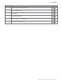
Contents
EM24 W1 5
Description 5
Structure 5
EM24 W1 use 6
Introduction 6
Display 6
Working with the measurement/info menu 7
Working with the settings menu 7
Setting a parameter 7
Setting wireless M-Bus parameters 9
Testing wireless M-Bus communication 10
Measurement menu - measurement pages 11
Information Menu 12
General settings 13
Essential information 14
Easy connection 14
Average value calculation (dmd) 14
Frames 14
Security proles 16
Encryption key 16
Frontal LED 16
Frontal selector 16
Maintenance and disposal 17

4EM24 W1 - Instruction manual | CARLO GAVAZZI Controls SpAEM24 W1 - Instruction manual | CARLO GAVAZZI Controls SpA
Information property
Copyright © 2018, CARLO GAVAZZI Controls SpA
All rights reserved in all countries.
CARLO GAVAZZI Controls SpA reserves the right to apply modifications or make improvements to the relative documentation
without the obligation of advance notice.
Safety messages
The following section describes the warnings related to user and device safety included in this document:
NOTICE: indicates obligations that if not observed may lead to damage to the device.
CAUTION! Indicates a risky situation which, if not avoided, may cause data loss.
IMPORTANT: provides essential information on completing the task that should not be neglected.
General warnings
This manual is an integral part of the product and accompanies it for its entire working life. It should be consulted for all
situations tied to configuration, use and maintenance. For this reason, it should always be accessible to operators.
NOTICE: no one is authorized to open the analyzer. This operation is reserved exclusively for CARLO GAVAZZI technical
service personnel.
Protection may be impaired if the instrument is used in a manner not specified by the manufacturer.
Service and warranty
In the event of malfunction, fault, requests for information, contact the CARLO GAVAZZI branch or distributor in your country.
Installation and use of analyzers other than those indicated in the provided instructions void the warranty.
Download
This manual www.productselection.net/MANUALS/UK/EM24_im_use.pdf
Installation instruction - EM24 www.productselection.net/MANUALS/UK/EM24_im_inst.pdf
UCS software www.productselection.net/Download/UK/ucs.zip

5EM24 W1 - Instruction manual | CARLO GAVAZZI Controls SpAEM24 W1 - Instruction manual | CARLO GAVAZZI Controls SpA
EM24 W1
Introduction
Description
EM24 is a three-phase energy analyzer for DIN-rail mounting, with configuration joystick and LCD display.
The direct connection version (AV2) allows to measure up to 65 A, the CT connection version (AV5) allows to measure up to 34875 A by
means of current transformers (5 A secondary output).
The wireless M-Bus communication allows to transmit the collected data.
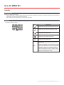
Structure
AV2 AV5
Part Description
ALCD display
BVoltage/current connections
CJoystick
DSelector with pin for MID seal (programming block)
ESMA connector (external antenna version)
FPins for MID seal (protection covers included)
GExternal antenna for wireless M-Bus communication
HSMA connector cable (2 m)

EM24 W1 - Instruction manual | CARLO GAVAZZI Controls SpA6EM24 W1 - Instruction manual | CARLO GAVAZZI Controls SpA
EM24 W1 use
Interface
Introduction
EM24 is organized in two menus:
• measurement and information menu: pages used to display the measurement pages, information relevant to the programmed parameters
and instrument firmware release
• settings menu: pages used to set parameters
Display
The display is divided into 3 lines.
Symbol Description
Displaying of phase-to-neutral system voltage
Displaying of phase-to-phase system voltage
Displaying of max values
Displaying of system variables
Displaying of dmd variables
EEEE
Overflow.
Note: in case of overflow of at least one current, hour
counter increase is disabled. The calculation of DMD
and the energy counters are calculated considering the
value of the measure in overflow as equal to the maxi-
mum managed by the instrument. “EEEE” in a single
phase variable automatically implies that the upper limit
of the related system variable has been exceeded, and
the indication of PF is forced to “1,000”.

7
EM24 W1 use
EM24 W1 - Instruction manual | CARLO GAVAZZI Controls SpAEM24 W1 - Instruction manual | CARLO GAVAZZI Controls SpA
Working with EM24 W1
Working with the measurement/info menu
Working with the settings menu
Setting a parameter
Example procedure: how to set Ct rAtio=20 and save changes.
Step Action Button
1 Power on the energy analyzer -
2 Press the joystick for at least 3 seconds
3 In the PASS? page, select the correct password (default 0)
4 Confirm operation
to next measurement page
to previous measurement page
to sengs menu
to previous info page to next info page
increase a parameter value
decrease a parameter value
edit/conrm
to previous page to next page

8
EM24 W1 use
EM24 W1 - Instruction manual | CARLO GAVAZZI Controls SpAEM24 W1 - Instruction manual | CARLO GAVAZZI Controls SpA
Step Action Button
5 Scroll pages until Ct rAtio
6 Enter the editing mode
7 Select 20
8 Confirm operation
9 Scroll pages until End
10 Confirm operation to exit

9
EM24 W1 use
EM24 W1 - Instruction manual | CARLO GAVAZZI Controls SpAEM24 W1 - Instruction manual | CARLO GAVAZZI Controls SpA
Wireless M-Bus communication setting
Setting wireless M-Bus parameters
Step Action Button
1 Press the button for at least 3 seconds
2 In the PASS? page, select the correct password (default 0)
3 Confirm operation
4 Scroll pages until ModE
5 Press the joystick to edit the parameter
6 Select the option
7 Confirm
8 Go to FrAME
9 Press the button to edit the parameter
10
Select the frame type according to the desired variables:
Variable Frame 1 Frame 2 Frame 3 Frame 4
Total imported active
energy
● ● ● ●
Total exported active
energy
●
Total imported reactive
energy
● ● ●
Total exported reactive
energy
● ● ●
Imported active power ● ● ●
Exported active power ●
Imported reactive power ● ●
Exported reactive power ● ●
Current L1 ●
Current L2 ●
Current L3 ●
Voltage L1-N ●
Voltage L2-N ●
Voltage L3-N ●
Supply frequency ●
Error flag ● ● ● ●
12 Confirm
13 Scroll pages until interVAL

10
EM24 W1 use
EM24 W1 - Instruction manual | CARLO GAVAZZI Controls SpAEM24 W1 - Instruction manual | CARLO GAVAZZI Controls SpA
Step Action Button
14 Press the button to edit the parameter
15 Select the option
16 Confirm
17 Scroll pages until EnCrYPt
18 Press the button to edit the parameter
19 Select the option
20 Confirm
21 Scroll pages until End
22 Confirm to exit
Testing wireless M-Bus communication
Step Action Button
1 Scroll Info pages until tr tESt
2 Press the button to force the communication
3 Verify if the master has received the message -

11
EM24 W1 use
EM24 W1 - Instruction manual | CARLO GAVAZZI Controls SpAEM24 W1 - Instruction manual | CARLO GAVAZZI Controls SpA
Menu description
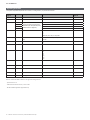
Measurement menu - measurement pages
The displayed pages depend on the version and settings.
Page Displayed measurements Description
1
L1-L2-L3
VLNΣ
Hz
Phase sequence
System phase-neutral voltage
Frequency
2
L1-L2-L3
VLLΣ
Hz
Phase sequence
System phase-phase voltage
Frequency
3
Tot kWh (+)
WΣ dmd
WΣ dmd max
Total imported active energy
System active power dmd
System active power dmd max
4
kWh
A dmd max
PArt
Partial imported active energy
Maximum dmd current
5
Tot kvarh (+)
VAΣ dmd
VAΣ dmd max
Total imported reactive energy
System apparent power dmd
System apparent power dmd max
6
kvarh
VAΣ
PArt
Partial imported reactive energy
System apparent power
7
Total kvarh (-)
VAΣ dmd
VAΣ dmd max
Total exported reactive energy
System apparent power dmd
System apparent power dmd max
8
Total kWh (-)
WΣ dmd
WΣ dmd max
Total exported active energy
System active power dmd
System active power dmd max
9
Hours
WΣ
PFΣ
Total load operating hours
System active power
System power factor
10
Hours
VArΣ
PFΣ
Total load operating hours
System reactive power
System power factor
11
var L1
var L2
var L3
Phase 1 reactive power
Phase 2 reactive power
Phase 3 reactive power
12
VA L1
VA L2
VA L3
Phase 1 apparent power
Phase 2 apparent power
Phase 3 apparent power
13
PF L1
PF L2
PF L3
Phase 1 power factor
Phase 2 power factor
Phase 3 power factor
14
W L1
W L2
W L3
Phase 1 active power
Phase 2 active power
Phase 3 active power
15
A L1
A L2
A L3
Phase 1 current
Phase 2 current
Phase 3 current
16
V L1-2
V L2-3
V L3-1
Phase 1-phase 2 voltage
Phase 2-phase 3 voltage
Phase 3-phase 1 voltage
17
V L1
V L2
V L3
Phase 1 voltage
Phase 2 voltage
Phase 3 voltage

12
EM24 W1 use
EM24 W1 - Instruction manual | CARLO GAVAZZI Controls SpAEM24 W1 - Instruction manual | CARLO GAVAZZI Controls SpA
Information Menu
Page Page title Information displayed
1CoMM rEV Firmware revision (communication)
2 StAtuS Device status
3 ModE Transmission mode
4 FrAME Frame type
5 interVAL Transmission interval
6 EnCrYPt Encryption
7tr tESt
Transmission test by pressing the joystick
• transmission counter
• transmission feedback (tr)
8id nuM Identification number for wireless M-Bus communication
9CT ratio CT ratio
10 1P/2P/3P/3Pn
(2-3-4-wire)
System
Connection (2-3-4-wire)
11 Pulse LED pulse weight (kWh/kvarh per pulse)
12 ChEcKSuM FW checksum for MID certification
13 Year Firmware release
Year of production

13
EM24 W1 use
EM24 W1 - Instruction manual | CARLO GAVAZZI Controls SpAEM24 W1 - Instruction manual | CARLO GAVAZZI Controls SpA
General settings
The available settings depend on the version, the settings and the selector position.
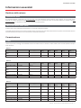
Page title Sub-menu Description Values Default value
Cng PASS - Change password From 0 to 9999 0
MEASurE Measure type A
b
A
SELECtor SELEC. 1 Page displayed according to selector
position among the available pages for
each application (see”Frontal selector”
on page 16)
From 1 to 17 1
SELEC. 2 From 1 to 17 3
SELEC. 3 From 1 to 17 3
SELEC.LoC From 1 to 17 3
SYS - System 3P.n
1P
3P
Note: MID (PFA, PFB): not available
3P.n
Ct rAtio - Current transformer ratio (CT) AV5: from 1 to 6975 (non MID)
AV2: N/A
1
ModE - Transmission mode t1
C1
t1
FrAME Frame type 1
2
3
4
2
intErVAL Interval 10 s
30 s
1 m
5 m
15 m
30 m
60 m
1 m
EnCrYPt Encryption prole no
a
b
a
EnE t.rES Total counter reset no
yes
no
EnE P.rES Partial counter reset no
yes
no
rESEt dmd max Dmd calculation and dmd max reset no
yes
no
End - Exit and save - -
Note: OMS certification is valid with the following settings:
- Frame type: 2 or 3
- Communication interval: 30 s, 1 m or 5 m
- Encryption enabled (security profile A or B)

14
Essential information
EM24 W1 - Instruction manual | CARLO GAVAZZI Controls SpAEM24 W1 - Instruction manual | CARLO GAVAZZI Controls SpA
Essential information
Measurement management
Easy connection
If the “Measure” parameter is set to A (easy connection), for the calculation of the active energy the power is always integrated, both in the case of imported
and exported power . The current direction does not affect the measurement. If the “Measure” parameter is set to B (without easy connection), both the active
imported and exported are available.
Average value calculation (dmd)
The system calculates the average value of electrical variables in a set integration interval.
Dmd values are available on display only. The dmd interval is automatically set equal to the transmission interval and it is not synchronized with the transmission
interval.
Communication
Frames
The frames are packages of messages sent by EM24 containing the variables measured. The variables and their encoding included in the frame depend on the
type of frame selected:
Frame 1
Variable Data Format Engineering unit DIF
[hex]
VIF
[hex]
VIFE#1
[hex]
VIFE#2
[hex]
VIFE#3
[hex]
Total imported active energy 32 bit integer Wh*100 04 05
Error ag 8 bit integer 01 FD 17
Frame 2
Variable Data Format Engineering unit DIF
[hex]
VIF
[hex]
VIFE#1
[hex]
VIFE#2
[hex]
VIFE#3
[hex]
Total imported active
energy
32 bit integer Wh*100 04 05
Total imported reactive
energy
32 bit integer kVarh*0.1 04 FB 82 75
Total exported reactive
energy
32 bit integer kVarh*0.1 04 FB 82 F5 3C
Imported active power 32 bit integer Watt*0.1 04 2A
Error ag 8 bit integer 01 FD 17
Frame 3
Variable Data Format Engineering unit DIF
[hex]
VIF
[hex]
VIFE#1
[hex]
VIFE#2
[hex]
VIFE#3
[hex]
Total imported active
energy
32 bit integer Wh*100 04 05
Total imported reactive
energy
32 bit integer kVarh*0.1 04 FB 82 75
Total exported reactive
energy
32 bit integer kVarh*0.1 04 FB 82 F5 3C
Imported active power 32 bit integer Watt*0.1 04 2A
Imported reactive power 32 bit integer Var 04 FB 14
Exported reactive power 32 bit integer Var 04 FB 94 3C

15
Essential information
EM24 W1 - Instruction manual | CARLO GAVAZZI Controls SpAEM24 W1 - Instruction manual | CARLO GAVAZZI Controls SpA
Frame 3
Variable Data Format Engineering unit DIF
[hex]
VIF
[hex]
VIFE#1
[hex]
VIFE#2
[hex]
VIFE#3
[hex]
Current L1 32 bit integer Ampere*0.001 04 FD D9 FC 01
Current L2 32 bit integer Ampere*0.001 04 FD D9 FC 02
Current L3 32 bit integer Ampere*0.001 04 FD D9 FC 03
Voltage L1-N 32 bit integer Volt*0.1 04 FD C8 FC 01
Voltage L2-N 32 bit integer Volt*0.1 04 FD C8 FC 02
Voltage L3-N 32 bit integer Volt*0.1 04 FD C8 FC 03
Frequency 16 bit integer Hz*0.1 02 FB 2E
Error ag 8 bit integer 01 FD 17
Frame 4
Variable Data Format Engineering unit DIF
[hex]
VIF
[hex]
VIFE#1
[hex]
VIFE#2
[hex]
VIFE#3
[hex]
Total imported active
energy
32 bit integer Wh*100 04 05
Total exported active
energy
32 bit integer Wh*100 04 85 3C
Total imported reactive
energy
32 bit integer kVarh*0.1 04 FB 82 75
Total exported reactive
energy
32 bit integer kVarh*0.1 04 FB 82 F5 3C
Imported active power 32 bit integer Watt*0.1 04 2A
Exported active power 32 bit integer Watt*0.1 04 AA 3C
Imported reactive power 32 bit integer Var 04 FB 14
Exported reactive power 32 bit integer Var 04 FB 94 3C
Error ag 8 bit integer 01 FD 17
Notes:
• the values transmitted - energy, current, voltage, frequency - are instant values, while power values are the average values within the transmission interval
• “error flag” is a diagnostic variable used to communicate an overflow condition which makes the measured data invalid:
Bit Meaning Notes
8
[MSb]
7654321
[LSb]
1P system 3P system • N.A. (not available): the bit cannot be set because the relevant
measurement is not dened, bit = 0.
• Frequency out of range is set when occurs an overow or an under-
ow of the frequency measured by measuring module.
• In system 3P, monitored voltages are the L-N voltages referred to a
virtual neutral.
0 0 0 0 0 0 0 0 No error
00000001 V1N overow
0 0 0 0 0 0 1 0 N.A. V2N overow
00000100 N.A.V3N overow
00001000 I1 overow
00010000 N.A. I2 overow
00100000 N.A. I3 overow
0 1 0 0 0 0 0 0 Frequency out of range

EM24 W1 - Instruction manual | CARLO GAVAZZI Controls SpA16
Essential information
EM24 W1 - Instruction manual | CARLO GAVAZZI Controls SpA
Frame available according to the EM24 model:
Frame type “X” models “PFA” models “PFB” models
1 X X X
2 X X X
3 X X X
4 X X
rror ag
Encryption
To ensure data privacy and prevent data access by unauthorized parties, you can enable M-Bus wireless communication data encryption.
Security proles
Two security profiles are available:
• Security profile A (ENC-Mode 5)
• Security profile B (ENC-Mode 7)
Encryption key
The encryption key is uniquely associated with each device. The key is included in a sealed envelope contained in the package of EM24.
IMPORTANT: KEEP THE ENCRYPTION KEY. In case of loss, it is not possible to recover the key and the tool can be used only without cryptography.
Frontal LED and selector
Frontal LED
The frontal red LED flashes proportionally to the active imported energy consumption if the selector is in - 1 - 2 position, and to the reactive inductive
energy consumption in kvarh position. Any kind of negative (exported) energy will not be managed by the front LED.
Frontal selector
• Lock position: the frontal selector prevents from accessing the programming mode of measurement parameters.
• 1, 2, kvarh position: quick access to measuring pages. Each position is associated with one measuring page.
Note: in MID versions the position in sealed in Lock .

17
Maintenance and disposal
EM24 W1 - Instruction manual | CARLO GAVAZZI Controls SpAEM24 W1 - Instruction manual | CARLO GAVAZZI Controls SpA
Maintenance and disposal
Cleaning
Use a slightly dampened cloth to clean the display. Do not use abrasives or solvents.
Responsibility for disposal
The product must be disposed of at the relative recycling centers specified by the government or local public authorities. Correct disposal
and recycling will contribute to the prevention of potentially harmful consequences to the environment and persons.

EM24 W1 - User manual
2021-06 | Copyright © 2019
CARLO GAVAZZI Controls SpA
via Safforze, 8
32100 Belluno (BL) Italy
www.gavazziautomation.com
info: +39 0437 355811
fax: +39 0437 355880

EM24 W1
Analizzatore di energia trifase
MANUALE D’USO

20 EM24 W1 - Manuale d'istruzioni | CARLO GAVAZZI Controls SpA
Indice
EM24 W1 22
Descrizione 22
Struttura 22
Utilizzo di EM24 W1 23
Introduzione 23
Visualizzazione 23
Utilizzo del menu misure/informazioni 24
Utilizzo del menu impostazioni 24
Impostazione di un parametro 24
Impostazione dei parametri dell’M-Bus wireless 26
Prova della comunicazione dell’M-Bus wireless 27
Menu misure - pagine delle misure 28
Menu Informazioni 29
Impostazioni generali 30
Informazioni essenziali 31
Connessione facile 31
Calcolo del valore medio (dmd) 31
Frame 31
Proli di sicurezza 33
Chiave di crittograa 33
LED frontale 33
Selettore frontale 33
Manutenzione e smaltimento 34
La page est en cours de chargement...
La page est en cours de chargement...
La page est en cours de chargement...
La page est en cours de chargement...
La page est en cours de chargement...
La page est en cours de chargement...
La page est en cours de chargement...
La page est en cours de chargement...
La page est en cours de chargement...
La page est en cours de chargement...
La page est en cours de chargement...
La page est en cours de chargement...
La page est en cours de chargement...
La page est en cours de chargement...
La page est en cours de chargement...
La page est en cours de chargement...
La page est en cours de chargement...
La page est en cours de chargement...
La page est en cours de chargement...
La page est en cours de chargement...
La page est en cours de chargement...
La page est en cours de chargement...
La page est en cours de chargement...
La page est en cours de chargement...
La page est en cours de chargement...
La page est en cours de chargement...
La page est en cours de chargement...
La page est en cours de chargement...
La page est en cours de chargement...
La page est en cours de chargement...
La page est en cours de chargement...
La page est en cours de chargement...
La page est en cours de chargement...
La page est en cours de chargement...
La page est en cours de chargement...
La page est en cours de chargement...
La page est en cours de chargement...
La page est en cours de chargement...
La page est en cours de chargement...
La page est en cours de chargement...
La page est en cours de chargement...
La page est en cours de chargement...
La page est en cours de chargement...
La page est en cours de chargement...
La page est en cours de chargement...
La page est en cours de chargement...
La page est en cours de chargement...
La page est en cours de chargement...
La page est en cours de chargement...
La page est en cours de chargement...
La page est en cours de chargement...
La page est en cours de chargement...
La page est en cours de chargement...
La page est en cours de chargement...
La page est en cours de chargement...
La page est en cours de chargement...
La page est en cours de chargement...
La page est en cours de chargement...
La page est en cours de chargement...
La page est en cours de chargement...
La page est en cours de chargement...
La page est en cours de chargement...
La page est en cours de chargement...
La page est en cours de chargement...
La page est en cours de chargement...
La page est en cours de chargement...
La page est en cours de chargement...
La page est en cours de chargement...
La page est en cours de chargement...
La page est en cours de chargement...
La page est en cours de chargement...
La page est en cours de chargement...
La page est en cours de chargement...
La page est en cours de chargement...
La page est en cours de chargement...
La page est en cours de chargement...
La page est en cours de chargement...
La page est en cours de chargement...
La page est en cours de chargement...
La page est en cours de chargement...
La page est en cours de chargement...
La page est en cours de chargement...
La page est en cours de chargement...
La page est en cours de chargement...
-
 1
1
-
 2
2
-
 3
3
-
 4
4
-
 5
5
-
 6
6
-
 7
7
-
 8
8
-
 9
9
-
 10
10
-
 11
11
-
 12
12
-
 13
13
-
 14
14
-
 15
15
-
 16
16
-
 17
17
-
 18
18
-
 19
19
-
 20
20
-
 21
21
-
 22
22
-
 23
23
-
 24
24
-
 25
25
-
 26
26
-
 27
27
-
 28
28
-
 29
29
-
 30
30
-
 31
31
-
 32
32
-
 33
33
-
 34
34
-
 35
35
-
 36
36
-
 37
37
-
 38
38
-
 39
39
-
 40
40
-
 41
41
-
 42
42
-
 43
43
-
 44
44
-
 45
45
-
 46
46
-
 47
47
-
 48
48
-
 49
49
-
 50
50
-
 51
51
-
 52
52
-
 53
53
-
 54
54
-
 55
55
-
 56
56
-
 57
57
-
 58
58
-
 59
59
-
 60
60
-
 61
61
-
 62
62
-
 63
63
-
 64
64
-
 65
65
-
 66
66
-
 67
67
-
 68
68
-
 69
69
-
 70
70
-
 71
71
-
 72
72
-
 73
73
-
 74
74
-
 75
75
-
 76
76
-
 77
77
-
 78
78
-
 79
79
-
 80
80
-
 81
81
-
 82
82
-
 83
83
-
 84
84
-
 85
85
-
 86
86
-
 87
87
-
 88
88
-
 89
89
-
 90
90
-
 91
91
-
 92
92
-
 93
93
-
 94
94
-
 95
95
-
 96
96
-
 97
97
-
 98
98
-
 99
99
-
 100
100
-
 101
101
-
 102
102
-
 103
103
-
 104
104


CARLO GAVAZZI EM24DINAV53XW1IX Manuel utilisateur
- Taper
- Manuel utilisateur