
LZW36 | Fan & Light Switch Red Si
www.inovelli.com/lzw36/setup contact@inovelli.com page 1
Thank You.
Thank you for taking the chance on us. We are truly humbled to be a part of your smart home journey and know that out of the
many companies out there, you trusted us to make your life simpler and we don’t take that for granted. Our mission is to provide
the best products, with the best customer support, at the best prices. Sure, every company says that... but we’d like to think
we’re dierent. Why? Well, because we have our own smart homes, with our own desires to make our life simpler through home
automation. We wake up every day to lights turning on to dierent colors based on the weather, coee automatically brewing
before we leave for work, and the thermostat changing based on our schedules. We take our nerdiness seriously by engaging in
online groups and design our products around community suggestions and needs. We don’t pretend to be a multi-billion dollar
corporation worried about shareholders and bottom line. We’re ok with being the little guy. The underdog, looking out for the best
interests of people like us... the everyday smart home enthusiast who is passionate about moving the industry forward and we
wouldn’t have it any other way. So again, from the bottom of our hearts, thank you for trusting us.
Z-Wave SmartStart
This device supports Z-Wave’s new SmartStart feature. Please do not throw out the card within the box that has your unique
QR Code with your DSK (Device Specific Key). This QR Code can also be found on the back of the switch (metal plate) and box.
HUB Installation Instructions.
All HUB’s are dierent, so why should your installation instructions be the same? Below you’ll find a QR Code to specific
instructions for your HUB (NOTE: If you don’t see your HUB, please scan the, “Other” QR Code). As you can imagine, it’s hard to
keep written instructions up to date with all the HUB/App changes, so the most recent instructions will be on the site. However,
if you’re a manual guy/gal, we get it, please see Page 7 for more details! If ever you run into any issues, please reach out to us at:
contact@inovelli.com.
Table of Contents: Page:
How Does the Fan & Light Switch Work? 2
About Z-Wave™ & Range Estimator Tool 3
Z-Wave Distance Worksheet & Best Practices for Installation 4
Wiring Disclaimers 5
Getting to Know Your Switch (LZW36) 6
Switch & Module Wiring (Neutral Required) 7
Installation Instructions (Canopy Module and In-Wall Switch) 7-8
Local Configuration Mode 8
Switch Parameters 9
FCC, Warranty and Z-Wave Information 10
Project Hurricane 11
SmartThings Wink Hubitat Other
inovelli.com/lzw36/setup/smartthings inovelli.com/lzw36/setup/wink inovelli.com/lzw36/setup/hubitat inovelli.com/lzw36/setup/other

LZW36 | Fan & Light Switch Red Si
www.inovelli.com/lzw36/setup contact@inovelli.com page 2
Technology Behind the Fan & Light Switch
There are two dierent wireless protocols that are used to make this fan & light switch. Z-Wave and RF. Z-Wave is what gives
the switch remote (smart) control, whereas RF is what connects the switch to the module. In other words, your hub/gateway
connects to your switch, where you can tell it to change the speed of the fan or the brightness of the lights. From there the
switch sends an RF command to the module to physically make those commands happen at the fan itself.
Z-Wave & RF Distance Notes
As mentioned above, there are two dierent protocols that are used with this switch and module combination. It’s important to
understand the limitations of the distances of RF and Z-Wave so that your switch and module can communicate eectively.
RF (Switch to Fan/Light Module): The maximum distance between the Switch and Module can be 32.8ft (10m)
Z-Wave (Switch to Hub): Please see Pages 3 & 4 to calculate the maximum distance
NOTE: Please start with your Z-Wave switch first to make sure it’s within distance and then make sure your module is within
distance of the switch.

Red Si LZW36 | Fan & Light Switch Red Si
www.inovelli.com/lzw36/setup contact@inovelli.com page 3
Best Practices for Pairing the Z-Wave Portion (Wall Switch) to Your Hub/Gateway:
Now that you’ve read how to calculate the Z-Wave range and have determined the best location to put your switch, it’s important
to understand some best practices of how to pair this device. Below are a few things to keep in mind when you start your
individualized pairing instructions (Pages 7-8).
NOTE: As mentioned on Page 2, please make sure your switch is within Z-Wave distance first, and then make sure the RF portion
(switch to module) is within distance (max distance apart is 32.8ft or 10m).
Calculate the Maximum Distance From the Worksheet Above and Place Well Within That Distance
Please use the worksheet above to calculate your maximum distance. This will save us both the headache of oine devices.
Remember to add all objects that could potentially be in the way and it’s our recommendation to be conservative with the
distance numbers.
If the Switch is Not Including, Try an Exclusion
Z-Wave devices can only be included (paired) to one HUB at a time. Sometimes, what happens is that the factory tests the
devices by including it to their network and forgets to remove the device from their network, causing the switch to believe that it’s
paired to the factory HUB. While this is extremely rare, it may happen. This can also happen if you purchased this switch used.
Follow the exclusion instructions located on Page 8 if you run into issues or check the range to make sure you are within
range of the HUB. Or, if you’ve installed it already, simply hold down the A + B buttons for (5) seconds to see whether or not the
switch is within range. If it lights up GREEN and stays GREEN after you’ve let go, then it’s within range, however, if it lights up
RED, then you are not within range.
Z-Wave Range Worksheet.
Feel free to use the below worksheet to give an estimate on where you can put your Z-Wave Switch relative to your HUB (or
other Z-Wave repeater). Below is an example of how to use the sheet, using, “Example 1” from Page 3.
For the starting Distance, use 100m. Then look directly
from your HUB to wherever you’d like to put the outlet
and see what obstacles are in the way. Then list those
obstacles on the worksheet below (using the charts
from Page 2).

LZW36 | Fan & Light Switch Red Si
www.inovelli.com/lzw36/setup contact@inovelli.com page 4
About Z-Wave.
Z-Wave is an incredible technology. With it powering your home, you can choose from over 600 companies and 2100 products,
all of which will work with each other. The more devices, the more stable the network. The purpose of this portion of the manual
is to help you understand how Z-Wave works (in layman’s terms) as well as help you organize an ecient Z-Wave network, setting
you up for success in the long run. After all, we’re assuming you’ll want more than one smart home device!
Z-Wave Network | Using Devices That Repeat Signals.
As referenced in the intro, Z-Wave can be used with a few devices or it can be used to build a large network. Below you’ll see two
examples. In the first example, a user has a HUB which is looking for Z-Wave devices within its radius. Z-Wave devices outside
this radius will not be found and need to either be moved within the radius or use a repeating device to reach it. The second
example shows how a repeater can be used to reach a device outside of the initial radius. Keep this in mind when building your
own network and make sure to use the range estimator below.
NOTE: Z-Wave range will never be a perfect circle due to walls, furniture, etc. The above is for reference only, please use the,
“Range Estimator” below and the Worksheet on Page 3 for a better idea of where to place your switch or whether or not your
chosen location will be in range.
Z-Wave Range Estimator.
Please use the below information to determine the depreciation of the Z-Wave signal. Z-Wave devices should have a distance
of approximately 100m (328ft) without any obstacles in the way. Using the below information, if a signal has to travel through an
inner wall, it will lose approximately 40% of its signal. Therefore, 100m multiplied by (100% - 40%) = 60m (197ft). Do this for every
wall, window, etc and you will have your approximation. There’s a worksheet on Page 3 that will help. As always, this is just an
estimate. Depending on the manufacturer’s quality for your other Z-Wave products, your signal may vary.

Red Si LZW36 | Fan & Light Switch Red Si
www.inovelli.com/lzw36/setup contact@inovelli.com page 5
Wiring Disclaimers
A quick note before we give out the wiring schematics. Please do not try installing this device if you are unsure of how
electrical circuits operate within your home. As exciting as it is to have a smart switch installed, it can be dangerous and even
life-threatening if you do not install this correctly. Please consult a qualified electrician if necessary as we are unable to give
wiring advice outside of schematics.
PLEASE NOTE: As of 05/25/19, we are unable to provide electrical and/or wiring advice outside of our schematics. If you are
unable to read a schematic or are not familiar with wiring, we suggest hiring an electrician. We apologize for any inconvenience.
Bulb Compatibility: We’ll keep a list of compatible bulbs in our community which can be found here:
https://support.inovelli.com/portal/kb/articles/lzw36-fan-light-switch-compatible-bulbs
CAUTION - PLEASE
READ!
ATTENTION -
VEUILLEZ LIRE SVP!
RECOMMENDED
INSTALLATION
PRACTICES
PRATIQUES
D’INSTALLATION
RECOMMANDÉES
OTHER
WARNINGS
AUTRES
AVERTISSEMENTS
MEDICAL
EQUIPMENT
ÉQUIPEMENT
MÉDICAL
This device (LZW36) is intended
for installation in accordance with
the National Electric Code and local
regulations in the United States, or
the Canadian Electrical Code and
local regulations in Canada. If you
are unsure or uncomfortable about
performing this installation consult a
qualified electrician.
This product is made for indoor
use only and is not designed or
approved for use on power lines other
than 120VAC, 60Hz, single phase.
Attempting to use the LZW36 on
non-approved power lines may have
hazardous consequences.
Cet appareil (LZW36) est conçu pour
être installé conformément au National
Electric Code et aux réglementations
locales aux États-Unis, ou au Canadian
Electrical Code et aux réglementations
locales au Canada. Si vous n’êtes pas
sûr ou mal à l’aise d’eectuer cette
installation, consultez un électricien
qualifié.
Ce produit est conçu pour une
utilisation en intérieur uniquement
et n’est pas conçu ou approuvé
pour une utilisation sur des lignes
électriques autres que 120 VCA, 60
Hz, monophasé. Tenter d’utiliser le
LZW36 sur des lignes électriques
non approuvées peut avoir des
conséquences dangereuses.
Risk of Fire
Risk of Electrical Shock
Risk of Burns
Risque d’incendie
Risque de choc électrique
Risque de brûlures
Please DO NOT use this switch
to control Medical or Life Support
equipment. Z-Wave devices should
never be used to control the On/O
status of Medical and/or Life Support
equipment.
Veuillez NE PAS utiliser cet interrupteur
pour contrôler l’équipement médical
ou de survie. Les appareils Z-Wave
ne doivent jamais être utilisés
pour contrôler l’état On / O des
équipements médicaux et / ou de
survie.
Use only indoors or in an outdoor rated
box
Turn o the circuit breaker -- Installing
this switch and module with the power on
will expose you to dangerous voltages
Connect only copper or copper-clad wire
to the switch or module
To reduce the risk of overheating and
possible damage to other equipment,
use the LZW36 load output to control
no more than 200 watts (Incandescent)
or 100W (LED/CFL) plus no more than 1
Amp of Fan load. Dimming an inductive
load (by connecting to the light load
wire), such as a fan or transformer, could
cause damage to the dimmer, the load
bearing device, or both.
To install your Fan/Light Switch, you’ll
need to identify the following four wires:
- Line: Usually black and can also be
called the HOT or LIVE, and carries
120VAC electricity into the electrical box
- Neutral: Usually white and is commonly
daisy chained from box to box, usually
appearing as a white wire bundle
- Load: Usually black, blue or red
- Ground: Bare copper wire or metal
fixture (if grounded)
If you are having diculties identifying
wires, please consult an electrician.
Utiliser uniquement à l’intérieur ou dans
une boîte classée extérieure
Éteignez le disjoncteur - L’installation de
cet interrupteur et de ce module sous
tension vous exposera à des tensions
dangereuses
Connectez uniquement du fil en cuivre ou
en cuivre au commutateur ou au module
Pour réduire le risque de surchaue
et les dommages possibles à d’autres
équipements, utilisez la sortie de charge
LZW36 pour contrôler pas plus de 200
watts (incandescent) ou 100W (LED /
CFL) plus pas plus de 1 ampère de charge
de ventilateur. La gradation d’une charge
inductive (en la connectant au fil de
charge légère), comme un ventilateur ou
un transformateur, pourrait endommager
le gradateur, le dispositif de support de
charge ou les deux.
Pour installer votre interrupteur ventilateur
/ éclairage, vous devez identifier les quatre
fils suivants:
- Ligne: généralement noire et peut
également être appelée HOT ou LIVE, et
transporte de l’électricité 120VAC dans le
boîtier électrique
- Neutre: généralement blanc et est
généralement connecté en guirlande d’une
boîte à l’autre, apparaissant généralement
sous la forme d’un faisceau de fils blancs
- Charge: généralement noire, bleue ou
rouge
- Masse: fil de cuivre nu ou luminaire
métallique (si mis à la terre)
Si vous éprouvez des dicultés à identifier
les fils, veuillez consulter un électricien.

LZW36 | Fan & Light Switch Red Si
www.inovelli.com/lzw36/setup contact@inovelli.com page 6
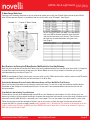
Getting to Know Your LZW36 Fan Switch
Now that you’re familiar with Z-Wave and how it works, it’s time to understand the basics of your new smart switch. For more
advanced configurations, please see Pages 8-10.
A. Light Dimmer (and Scene Control*): This button can be used to
increase or decrease the dimness level on your light. Press (hold) up to
increase brightness and press (hold) down to decrease the brightness.
Also, a single press will send a scene command to your hub.
B. Light On/O Button (and Scene Control*): Press this button to turn
on and o the fan light(s). This button can also be used to trigger Z-Wave
scenes. You may add up to 7 scenes (Tap 1x, 2x, 3x, 4x, 5x, Hold, Release).
C. Light RGB LED Bar (with Notifications*): Shows the level at which the
fan light(s) are set at. In addition, it can be used as a notifier for various
events (i.e.: turn purple if front door is open).
D. Fan Speed (and Scene Control*): This button can be used to increase
or decrease the speed of your fan. Press (hold) up to increase the speed
and press (hold) down to decrease the speed. Also, a single press will send
a scene command to your hub.
E. Fan On/O Button (and Scene Control*): Press this button to turn on
and o the fan. This button can also be used to trigger Z-Wave scenes. You
may add up to 7 scenes (Tap 1x, 2x, 3x, 4x, 5x, Hold, Release).
F. Light RGB LED Bar (with Notifications*): Shows the level at which the fan speed is set at. In
addition, it can be used as a notifier for various events (i.e.: turn red when your alarm is armed).
G. Air Gap Switch: This will reboot the switch if it needs to be rebooted (NOTE: The air-gap switch
will not cut power to the module).
NOT SHOWN: Energy Monitoring* and Scene Control* are built-in features of this switch as well.
* Please make sure your
HUB supports these
features. See website for
more details.
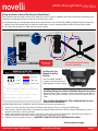
Getting to Know Your LZW36 Fan Module
H. Line Wire (Black): This wire will be what powers the
module.
I. Neutral Wire (White): This is needed to keep power to
the RF chip.
J. Light Load (Blue): This is what connects to the fan’s
light wire.
K. Fan Load (Red): This is what connects to the fan’s
motor wire.
L. RF Antenna: This is the module’s RF antenna.
NOTE: If power is cut to the switch and module, it will take
approximately 30 seconds to reconnect.
Full wires not shown
A
B
C
D
E
F
H
I
J
K
L
Button Combination Cheat Sheet
G
Button Combination Result
Hold A + B for 10 Seconds Enter Local Config Mode
Hold A + Tap B 2x Dismiss Light Notification
Hold D + Tap E 2x Dismiss Fan Notification
Hold A + Tap B 3x Enter Z-Wave Inclusion /
Exclusion Mode
Hold D + Tap E 3x Enter Fan Module Pairing
Mode
Hold A + Tap B 8x Enable Local Protection on
Light Buttons (Disable Relay)
Hold D + Tap E 8x Enable Local Protection on
Fan Buttons (Disable Relay)
Hold A + B for 5 Seconds Detect Z-Wave Network
Signal
Hold A + B for 20 Seconds Z-Wave Factory Reset
Hold D + E for 20 Seconds Fan Module Factory Reset

Red Si LZW36 | Fan & Light Switch Red Si
www.inovelli.com/lzw36/setup contact@inovelli.com page 7
Wiring Instructions: Neutral Wire Required (Quick Notes)
Please note that you will need a neutral wire in order to install this switch. In addition, you will be connecting the Line/Hot to the
Load. Here are some quick notes to read prior to installing your switch:
If you do not see your wiring diagram here, please check online as we will constantly update and add schematics to our site
and also have a forum where you can help each other. Again, we can no longer provide specific wiring or electrical help.
This switch will not work in a 3-Way (or multi-switch) setting.
Your fan module should fit
snuggly in the fan bracket that
helps hold your fan to the ceiling.
Installing the Fan
Module in the Fan
Bracket
Including (Pairing) Your Switch & Module: General Instructions
Below are step by step instructions on how to pair your fan switch and fan
module. For hub specific instructions, please use the QR codes or URL’s on
Page 1.
Step 1: Gather Your Materials, Find an Appropriate Location,
and Install the Fan Switch
Materials Needed: Wire nuts, screwdriver, and access to both the line (hot) and neutral wires.
Locate an area to install your switch within the recommended distance (Pages 3-4) from your HUB/Gateway.
Walls, furniture, and other obstructions may degrade the communication between the Switch and your HUB/Gateway, so please
keep this in mind when selecting a location.
Before cutting power to your switch and fan, using the fans pull chains, set the fan to the highest speed and turn the light(s) on.
Moving forward you will no longer need to use the pull chains to control the fan or light(s).
Follow the wiring instructions on page 7 -- REMEMBER: TURN OFF ELECTRICITY BEFORE INSTALLATION!
Continued on next page . . .
see inovelli.com/lzw36-wiring
for more schematics

LZW36 | Fan & Light Switch Red Si
www.inovelli.com/lzw36/setup contact@inovelli.com page 8
NOTE: If you’d like to verify if the switch is within range of your Z-Wave hub before installing the canopy module, feel free to turn the
power back on. The switch should light up and run through a series of colors before finally turning blue. Once the switch LED bars
are blue, hold down the top of Button A and Button B for 5 seconds and the switch LED’s will turn Green. Release the buttons and if
the switch LED’s remain Green, then the switch is within Z-Wave range. If the LED bars turn Red, then the switch is not within range.
Step 2: Installing the Fan Canopy Module
Materials Needed: Wire nuts, screwdriver, access to a neutral (white), load (black), fan and light wires and the included zip-tie.
Ensure the distance between your fan switch and module is no more than 32.8ft (10m) as that is the
maximum distance the RF signal can travel from the switch to the canopy module.
Remove your ceiling fan from the electrical box and identify the load (black -- which is now hot),
neutral (white), and the fan motor and light loads (usually red is the fan and blue is the light, but your
wires may be dierent).
Connect the wires together as shown on Page 7 or as shown in Figure 1.1.
Once completed, it’s time to check to make sure everything works and is paired correctly. Please
fasten the canopy to the fan bracket using the included zip-tie (as shown on page 7), ensure all
connections are secure with no exposed copper and re-assemble your fan.
Step 3: Pairing the Switch to the Canopy Module
Now that everything is installed, and your fan is re-assembled it’s time to pair the switch to the canopy module.
NOTE: The fan module should be paired to the Z-Wave switch from the factory. In case you have an issue,
below is how you can manually do so. Warning: Do not try to test the fan without it being secured to the ceiling.
With the fan secured to the ceiling and the switch secured to the wall, let’s start the pairing process of the switch and module.
To pair the switch to the module, apply power from the circuit breaker to both devices. Note: After trying to pair to the Z-Wave switch for 30 seconds, if not
successful, the fan module goes into pairing mode for 2 minutes. You can tell it is in this mode by the bulb in the fixture pulsing.
Press and hold Button D and press Button E 3x. If successful, the LED bar will blink Green.
You should now be able to control the fan speed and light brightness from the switch manually. Press Buttons B & E
to turn the fan and light on and o, and hold up and down Buttons A & D to change the fan speed and light dim level.
Step 4: Pairing the Switch to Your Hub/Gateway
Now that your switch and canopy module are paired, it’s time to pair your switch to your Z-Wave enabled hub or gateway.
Enable the inclusion process on your Hub or Gateway.
Hold down button A and press button B 3x quickly and your LED Bars will pulse blue signifying the
switch is in inclusion mode. If successful, the switch LED Bars will flash Green and if unsuccessful, the
LED Bars will flash Red.
If the LED Bars flash Red, please check your Z-Wave signal by referencing the Note at the top of the page.
If your switch is within range, you may want to try an exclusion. Instructions are to the right.
Switch (Local) Configuration Mode
There are a couple dierent ways you can set the configuration parameters of your switch (listed on page 9). It is recommended that you
set them from your hub when possible, but if not, you can set them directly from the switch! For more detailed instructions, please check our
support webpage at support.inovelli.com. Here are some basic instructions:
Enter into either light configuration mode or fan configuration mode based on which parameters you want to edit. Light: Hold down the A
Button + B Button for 10 Seconds. Fan Hold down the D Button + E Button for 10 Seconds.
Press either the light on/o button (B) or the fan on/o button (E) the number of times that corresponds with the parameter you want
to change (listed on page 9).
Use the light level up/down (A) or fan level up/down (D) buttons to set the parameter to the number you would like. Each press
increments the value by 1.
The LED on the switch will flash yellow to show you which parameter number you are editing. The LED will also flash purple to show you
the value that you have assigned. A long flash represents 10s and a short flash represents 1s. So, for example, two long flashes followed by
three short flashes would represent 23.
After you are finished, press and hold JUST the B or E button (depending on whether you are editing the light or fan configuration) for 10
seconds to save and exit.
1.
2.
3.
4.
5.
Figure 1.1
Having Problems
Including? Try an
Exclusion
Place your hub or gateway
into exclusion mode. Then:
Hold button A + Press
Button B 3x. If it is
successful the LED will
blink green.
Then, try including again.
Avertissement: N’essayez pas de tester le ventilateur sans qu’il soit fixé au plafond.

Red Si LZW36 | Fan & Light Switch Red Si
www.inovelli.com/lzw36/setup contact@inovelli.com page 9
Switch Parameters
Below you’ll find the various parameters associated with your switch. There are a ton of options for customization and as you can
imagine, it’s hard to write out all the possibilities in a manual. Please use this as a guide, but also feel free to check out our site
where we’ll give some specific examples using each parameter.
Param # Change at
the switch?
Switch
Config #
Light
or Fan
Name Description Size Range Default
1 Yes 1 L Dimming Speed This changes the speed in which the attached light dims up or down. A setting of 0 should turn the light immedi-
ately on or o (almost like an on/o switch). Increasing the value should slow down the transition speed.
1 0..100 3
2 No L Dimming Speed
(From Switch)
This changes the speed in which the attached light dims up or down when controlled from the physical switch. A
setting of 0 should turn the light immediately on or o (almost like an on/o switch). Increasing the value should
slow down the transition speed. A setting of 99 should keep this in sync with parameter 1.
1 0..99 99
3 No L Ramp Rate This changes the speed in which the attached light turns on or o. For example, when a user sends the switch a
basicSet(value: 0xFF) or basicSet(value: 0x00), this is the speed in which those actions take place. A setting of 0
should turn the light immediately on or o (almost like an on/o switch). Increasing the value should slow down the
transition speed. A setting of 99 should keep this in sync with parameter 1.
1 0..99 99
4 No L Ramp Rate (From
Switch)
This changes the speed in which the attached light turns on or o from the physical switch. For example, when a
user presses the up or down button, this is the speed in which those actions take place. A setting of 0 should turn
the light immediately on or o (almost like an on/o switch). Increasing the value should slow down the transition
speed. A setting of 99 should keep this in sync with parameter 1.
1 0..99 99
5 Yes 2 L Minimum Level The minimum level that the dimmer allows the bulb to be dimmed to. Useful when the user has a bulb that does not
turn on at a lower level.
1 1..45 1
6 Yes 3 L Maximum Level The maximum level that the dimmer allows the bulb to be dimmed to. Useful when the user has an LED bulb that
reaches its maximum level before the dimmer value of 99.
1 55..99 99
7 Yes 1 F Minimum Level The minimum level that the dimmer allows the fan to be dimmed to. Useful when the user has a fan that does not
turn on at a lower level.
1 1..45 1
8 Yes 2 F Maximum Level The maximum level that the dimmer allows the fan to be dimmed to. 1 55..99 99
10 No L Auto O Timer Automatically turns the light o after this many seconds. When the switch is turned on a timer is started that is the
duration of this setting. When the timer expires, the switch is turned o.
2 0..
32767
0
11 No F Auto O Timer Automatically turns the fan o after this many seconds. When the fan is turned on a timer is started that is the
duration of this setting. When the timer expires, the fan is turned o.
2 0..
32767
0
12 Yes 4 L Default Level (Local) Default level for the dimmer when it is powered on from the local switch. A setting of 0 means that the switch will
return to the level that it was on before it was turned o.
1 1..99 0
13 Yes 5 L Default Level (Z-
Wave)
Default level for the dimmer when it is powered on from a Z-Wave command. A setting of 0 means that the switch
will return to the level that it was on before it was turned o.
1 1..99 0
14 Yes 3 F Default Level (Local) Default level for the fan when it is powered on from the local switch. A setting of 0 means that the switch will return
to the level that it was on before it was turned o.
1 1..99 0
15 Yes 4 F Default Level (Z-
Wave)
Default level for the fan when it is powered on from a Z-Wave command. A setting of 0 means that the switch will
return to the level that it was on before it was turned o.
1 1..99 0
16 Yes 6 L After Power Restored The state the switch should return to once power is restored after power failure. 0 = o, 1-99 = level, 100=previous. 1 0..100 100
17 Yes 5 F After Power Restored The state the switch should return to once power is restored after power failure. 0 = o, 1-99 = level, 100=previous. 1 0..100 0
18 Yes 7 L LED Indicator Color This is the color of the Light LED strip represented as part of the HUE color wheel. Since the wheel has 360 values
and this parameter only has 255, the following equation can be used to determine the color: value/255 * 350 = Hue
color wheel value
2 0..255 170
19 Yes 8 L LED Strip Intensity This is the intensity of the Light LED strip. 1 0..10 5
20 Yes 6 F LED Indicator Color This is the color of the Fan LED strip represented as part of the HUE color wheel. Since the wheel has 360 values
and this parameter only has 255, the following equation can be used to determine the color: value/255 * 350 = Hue
color wheel value
2 0..255 170
21 Yes 7 F LED Strip Intensity This is the intensity of the Fan LED strip. 1 0..10 5
22 Yes 9 L LED Strip Intensity
(When OFF)
This is the intensity of the Light LED strip when the switch is o. This is useful for users to see the light switch
location when the lights are o.
1 0..10 1
23 Yes 8 F LED Strip Intensity
(When OFF)
This is the intensity of the Fan LED strip when the switch is o. This is useful for users to see the light switch loca-
tion when the lights are o.
1 0..10 1
24 No L LED Strip Eect This will allow you to add some sweet eects to your LED Bar (i.e.: pulse, chase, solid, etc). Byte 1 = Color, Byte 2 =
Brightness Level, Byte 3 = Eect, Byte 4 = Duration. *Please see https://inovelli.com/lzw36/notifications
4 0..83-
823359
0
25 No F LED Strip Eect This will allow you to add some sweet eects to your LED Bar (i.e.: pulse, chase, solid, etc). Byte 1 = Color, Byte 2 =
Brightness Level, Byte 3 = Eect, Byte 4 = Duration. *Please see https://inovelli.com/lzw36/notifications
4 0..83-
823359
0
26 Yes 10 L LED Strip Timeout When the LED strip is disabled (Light LED Strip Intensity is set to 0), this setting allows the LED strip to turn on
temporarily while being adjusted.
1 0..10 3
27 Yes 9 F LED Strip Timeout When the LED strip is disabled (Fan LED Strip Intensity is set to 0), this setting allows the LED strip to turn on
temporarily while being adjusted.
1 0..10 3
28 No L/F Active Power Reports The power level change that will result in a new power report being sent. The value is a percentage of the previous
report. 0 = disabled.
1 0..100 10
29 No L/F Periodic Power &
Energy Reports
Time period between consecutive power & energy reports being sent (in seconds). The timer is reset after each
report is sent.
2 0..
32767
3600
30 No L/F Energy Reports Energy level change which will result in sending a new energy report. Available settings: 1-127 (0.01-1.27 kWh) 0 =
disabled.
1 0..100 10

LZW36 | Fan & Light Switch Red Si
www.inovelli.com/lzw36/setup contact@inovelli.com page 10
Z-Wave Command Classes
5E - COMMAND_CLASS_ZWAVEPLUS_INFO
55 - COMMAND_CLASS_TRANSPORT_SERVICE
98 - COMMAND_CLASS_SECURITY
9F - COMMAND_CLASS_SECURITY_2
6C - COMMAND_CLASS_SUPERVISION
26 - COMMAND_CLASS_SWITCH_MULTILEVEL
70 - COMMAND_CLASS_CONFIGURATION
85 - COMMAND_CLASS_ASSOCIATION
59 - COMMAND_CLASS_ASSOCIATION_GRP_INFO
86 - COMMAND_CLASS_VERSION
72 - COMMAND_CLASS_MANUFACTURER_SPECIFIC
5A - COMMAND_CLASS_DEVICE_RESET_LOCALLY
73 - COMMAND_CLASS_POWERLEVEL
75 - COMMAND_CLASS_PROTECTION
22 - COMMAND_CLASS_APPLICATION_STATUS
7A - COMMAND_CLASS_FIRMWARE_UPDATE_MD
5B - COMMAND_CLASS_CENTRAL_SCENE_V3
8E - COMMAND_CLASS_MULTI_CHANNEL_ASSOCIATION_V2
87 - COMMAND_CLASS_INDICATOR
60 - COMMAND_CLASS_MULTI_CHANNEL_V4
Group 1: Lifeline -- Members of this group will receive unsolicited messages related to
the status of the switch.
Group 2: Basic Set - Light -- Sends On & O commands to associated devices. (1. Single
press UP button sends BasicSet (0xFF) and 2. Single press Down sends BasicSet (0x00)
Group 3: Switch Multilevel Set - Light -- Sends set level commands to associated
devices when switch is pressed.
(1. Hold & Release Up or Down button sends SwitchMultiLevelSet which keeps associated
devices in sync with this device. 2. Single press Up button sends SwitchMultiLevelSet(0x
FF) and 4. Single press Down button sends SwitchMultiLevelSet(0x00)
Group 4: Switch Multilevel Set - Light -- Sends start / stop level change to associated
devices.
(1. Hold Up button sends SW_MULTILEVEL_START_LEVEL_CHANGE (Up)
2: Hold Down button sends SW_MULTILEVEL_START_LEVEL_CHANGE (Down) 3.
Release Either button sends SW_MULTILEVEL_STOP_LEVEL_CHANGE
Group 5: Basic Set - Fan -- Sends On & O commands to associated devices. (1. Single
press UP button sends BasicSet (0xFF) and 2. Single press Down sends BasicSet (0x00)
Group 6: Switch Multilevel Set - Fan-- Sends set level commands to associated devices
when switch is pressed.
(1. Hold & Release Up or Down button sends SwitchMultiLevelSet which keeps associated
devices in sync with this device. 2. Single press Up button sends SwitchMultiLevelSet(0x
FF) and 4. Single press Down button sends SwitchMultiLevelSet(0x00)
Group 7: Switch Multilevel Set - Fan -- Sends start / stop level change to associated
devices.
(1. Hold Up button sends SW_MULTILEVEL_START_LEVEL_CHANGE (Up)
2: Hold Down button sends SW_MULTILEVEL_START_LEVEL_CHANGE (Down) 3.
Release Either button sends SW_MULTILEVEL_STOP_LEVEL_CHANGE
Federal Communications Commission (FCC) Statement
FCC Caution: Any changes or modifications not expressly approved by the party responsible for compliance could void the user’s authority to operate this
equipment. This device complies with Part 15 of the FCC Rules. Operation is subject to the following two conditions: (1) This device may not cause harmful
interference, and (2) this device must accept any interference received including interference that may cause undesired operation.
NOTE: This equipment has been tested and found to comply with the limits for a Class B digital device, pursuant to Part 15 of the FCC Rules. These limits are
designed to provide reasonable protection against harmful interference in a residential installation.
This equipment generates, uses and can radiate radio frequency energy and, if not installed and used in accordance with the instructions, may cause harmful
interference to radio communications. However, there is no guarantee that interference will not occur in a particular installation. If this equipment does cause
harmful interference to radio or television reception, which can be determined by turning the equipment o and on, the user is encouraged to try to correct the
interference by one or more of the following measures: Reorient or relocate the receiving antenna, increase the separation between the equipment and receiver,
connect the equipment into an outlet on a circuit dierent from that to which the receiver is connected or consult the dealer or an experienced radio/TV technician
for help. This equipment should be installed and operated with minimum distance 8in (20cm) between the radiator and your body.
IC Caution: This device complies with Industry Canada licence-exempt RSS standard(s). Operation is subject to the following two conditions: (1) this device may not
cause interference, and (2) this device must accept any interference, including interference that may cause undesired operation of the device.
DECLARATION DE CONFORMITE D’INDUSTRIE CANADA: Ce périphérique a été testé et reconnu conforme aux limites spécifiées dans RSS-210. Son
utilisation est soumise aux deux conditions suivantes: (1) il ne doit pas provoquer d’interférences gênantes et (2) il doit tolérer les interférences re.ues, notamment
cellessusceptibles d’en perturber le fonctionnement. Cet équipement doit être installé et utilisé à une distance minimale de 20 cm entre le radiateur et votre corps.
Warranty and Specifications
Warranty: Inovelli will replace any defective unit for the lifetime of the unit, pending the unit was used in the manner it was intended to. Please email us at:
contact@inovelli.com or visit us at www.inovelli.com/warranty for full details.
Specifications for Model # LZW36:
Power: 120V AC, 60Hz, Signal (Frequency): 908.42 MHz, Operating Temperature Range: 32-95° F (0-35° C)
Maximum Load: 200W Incandescent, or 100W LED / CFL
Range: Up to 100 meters line of sight between the Wireless Controller (HUB) and the closest Z-Wave Module
For indoor use. Specifications subject to change without notice due to continuing product improvement.
Approval: UL Listed / FCC / IC / Z-Wave Plus™ Certified
CAN ICES-003 (B)/NMB-003(B)
Resetting Your Device
You may hold the Light Level
Button (A) + Light On/O Button
(B) for 20 seconds or use a
certified controller to remove
the device from your network
to factory default. Only use this
procedure in the event that the
network primary controller is
missing or otherwise inoperable.
OTA NOTE
Over-the-Air updates are available
on this switch. It will take about 1
minute after completion for it to,
“settle”, so please leave the switch
alone for a minute after flashing.
If the power is cut o immediately
after OTA is completed, OTA may
fail.
Z-Wave Association Groups
Group # Max Nodes Commands
Group 1 5 1. Central Scene
2. Basic Report
3. Multilevel Report
4. Protection Report
5. Device Reset Locally
6. Meter Report
Group2 (Light)
Group5 (Fan)
5 Basic Set
Group3 (Light)
Group6 (Fan)
5 Switch Multilevel Set
Group4 (Light)
Group7 (Fan)
5 Switch Multilevel Set

Red Si LZW36 | Fan & Light Switch Red Si
www.inovelli.com/lzw36/setup contact@inovelli.com page 11
Project Hurricane
You may have noticed our signatures and project name on the inside of the box and wondered, “what is that all about?”. Well,
great question! All of our products have a project name associated with them that means something to us and speaks directly to
the device itself. It’s personality if you will. In addition to the project name, our signatures indicate that we’ve all signed o on the
project. We believe in the project and worked hard, along with you, to bring it to life.
Project, “Hurricane” has a couple of meanings to it. The first meaning was that this device was one of the first smart home
products ever requested by the community, even before Inovelli started. I was attending the University of Miami (Hurricanes) and
one of the projects we had to do involved smart home products. I put a poll out to see what the most requested product was
that doesn’t exist yet and the fan/light combo was it. So, project, “Hurricane” is a shout out to my alma-mater as without us doing
a project in class, Inovelli (and project, “Hurricane”) wouldn’t exist. The other meaning is just silly in that it’s a fan that creates
breeze and of course Hurricane’s produce wind.
Anyway, thank you not only for your support, but for helping us put out the first Z-Wave Fan & Light module. A special thank you
goes out to our Beta Testers as well, we couldn’t have done it without you!
Project Hurricane has been my favorite innovation project to work on. It’s been something I’ve
wanted personally ever since I began my smart home journey. I’ve been able to automate everything
in my house except these darn fans and, of course, it’s the one thing my daughters always leave on!
Anyway, we’re super pumped to be the first to oer these in Z-Wave and hope you like them too.
This has been an exciting project for me. It will be our first Z-Wave 700 series product to go to
market and is one of (if not) the first in the industry. Other than being the first in that regard, It has
an innovative design that utilizes Z-Wave & RF to provide a compact product that solves a need that
has been in the smart home market for many years. Inovelli customers can rejoice knowing that they
finally have a highly capable device to control the fans in their home.
The fan and light switch is going to be huge for the smart home industry. There are so many ceiling
fans out there that just want a little automation in their lives! The part I’m most excited about is the
scenes, notifications and all the other bells and whistles that come with this switch. Finally, the fact
that we had an entire group of community beta testers testing this has been amazing.
Working with the team on this was so much fun. Watching everyone get excited about making
something that has been asked for going on three years now from the community was truly an
amazing experience. I can’t wait to start posting on social, sending out emails and letting the world
know about these switches!
This project holds a special place in my heart in that it was the first one I really got to manage on my
own. It had its fair share of challenges (literally a pandemic happening) but we’ve pulled through and
came out with a pretty awesome product that’s being used in my own smart house! It was also really
cool to work with the community to bring this project to life -- it really felt like a team eort.
Eric H.
Founder / CEO
Eric M.
CTO
Nathan
CSO
Brianna
Sr. Marketing
Manager
Courtney
Operations
Manager
-
 1
1
-
 2
2
-
 3
3
-
 4
4
-
 5
5
-
 6
6
-
 7
7
-
 8
8
-
 9
9
-
 10
10
-
 11
11


