Mitsubishi PVA-A12 P-Series Air Conditioners Manuel utilisateur
- Catégorie
- Climatiseurs split-system
- Taper
- Manuel utilisateur

Air-Conditioners
PVA-A12, 18, 24, 30, 36, 42 AA7
INSTALLATION MANUAL
For safe and correct use, please read this installation manual thoroughly before installing the air-conditioner unit.
FOR INSTALLER
P-SERIES
MANUEL D'INSTALLATION
Veuillez lire le manuel d’installation en entier avant d’installer ce climatiseur pour éviter tout accident et vous
assurer d’une utilisation correcte.
POUR L’INSTALLATEUR
English
Français

2
EE
EN
Contents
Contents .....................................................................................2
1. Dimensions .............................................................................3
2. Inspect shipment ....................................................................4
3. Safety precautions ..................................................................4
3.1. Before installation and electric work ..............................4
3.2. Precautions for devices that use R410A refrigerant ......5
3.3. Before getting started ....................................................5
3.4. Before getting installed (moved)-electrical work ............5
3.5. Before starting the test run ............................................6
4. Indoor unit accessories...........................................................6
5. Selecting an installation site ...................................................6
6. Combining indoor units with outdoor units..............................6
7. Installing the unit.....................................................................7
8. Duct connection ......................................................................7
9. Mount positions ......................................................................8
9.1. Vertical installations .......................................................8
9.2. Horizontal right installations ...........................................9
9.3. Horizontal left installations ...........................................10
9.4. Downow installations .................................................14
10. Air lter................................................................................16
11. Refrigerant piping work .......................................................17
11.1. Insulation ....................................................................18
11.2. Piping size ..................................................................18
12. Drain connections ...............................................................19
13. Electrical wiring...................................................................20
13.1. Remote controllers .....................................................21
13.2. Connecting line voltage, Function Table ....................22
13.3. Condensate overow safety switch connection
(CN4F) ...................................................................23
13.4. Changing blower external static pressure ..................23
13.5. ERV (energy recovery ventilation) .............................24
13.6. Humidier ...................................................................25
14. Test run ...............................................................................26
14.1. Before test run ...........................................................26
14.2. Test run ......................................................................26
14.3. Self-check ..................................................................26
14.4. AUTO RESTART FUNCTION ....................................28

3
EE
EN
1. Dimensions
(18-3/16)
(20X24X1) (22-13/16X15-7/8)
(31-3/16)
(18-13/16) (15-1/8) (10-1/2) (54-1/4) (29-1/16) (37-9/16)
(25) (22-13/16) (19-1/8) (12-1/2) (31-7/16) (41-1/2) (33-5/8) (22-3/16)
(21)
(20X20X1) (18-13/16X15-7/8)
Model ABCDEFGHJGas pipe Liquid pipe
PVA-A30AA4 477 382.6 266.5 1378 737 953.5
PVA-A36AA4 635 579 484.6 317.5 1511
(59-1/2)
798.5 1053 853.5 563
PVA-A42AA4
Model Nominal Filter size Duct Connection
PVA-A30AA4
PVA-A36AA4
PVA-A42AA4
(5/8) (3/8)
461
534
508X609.6X25.4
508X508X25.4
579X402
477X402
J
77.8(3-1/8)
66(2-5/8)
36.8(1-1/2)
43(1-3/4) 8(3/8)
92(3-5/8) 30(1-3/16)
43(1-3/4)
8(3/8)
55(2-3/16)
548(21-5/8)
117.4 (4-5/8)
402(15-7/8)
B(Duct) 28.8(1-3/16)
76(3)
C
A
D
525.5(20-3/4)50.8(2)470(18-9/16)
H55(2-3/16)
G70(2-13/16)
8(3/8)
F
55(2-3/16)
E24(15/16)
13.2(9/16)
Control box
Air filter
Air outlet
Air inlet
(Duct)
Refrigerant piping
brazing connection(gas)
Refrigerant piping
brazing connection(liquid)
Primary drain pipe
(Gravity drain)
ø19.05(3/4) 3/4"FPT
Secondary drain pipe
(Emergency draining)
ø19.05(3/4) 3/4"FPT
Primary drain pipe
(Gravity drain)
ø19.05(3/4) 3/4"FPT
(Horizontal left)
(Horizontal Right)
Secondary drain pipe
(Emergency draining)
ø19.05(3/4) 3/4"FPT
Primary drain pipe
(Gravity drain)
ø19.05(3/4) 3/4"FPT
Secondary drain pipe
(Emergency draining)
ø19.05(3/4) 3/4"FPT
Te rminal block
(Indoor / Outdoor unit connection)
Te rminal block
(Remote controller transmission)
2-ø4.6 Burring Holes
for electric heat installation
ø26 Knockout Hole
(Remote controller transmission)
ø26 Knockout Hole
ø26 Knockout Hole
ø26 Knockout Hole
(Indoor / Outdoor unit connection)
(Indoor /Outdoor
unit connection)
(Remote controller transmission)
792
Ø15.88 Ø9.52
Note 1.Keep the service space for maintenance at the front.
Unit:mm(in.)
To p
To p
view
Front
Bottom
Bottom
view
view
Left side
view Right side
view
1
3
3
2
1
2
Unit: mm (in.)
Model A B C D E F G H J Gas Pipe Liquid Pipe
PVA-A12AA7 432 (17) 376 (14-13/16) 281 (11-1/8) 224 (8-7/8) 1275 (50-1/4) 680 (26-13/16) 823 (32-7/16) 735.5 (29) 360 (14-3/16) Φ 12.7 (1/2) Φ 6.35 (1/4)
PVA-A18AA7
PVA-A24AA7 534 (21) 477 (18-13/16) 382.6 (15-1/8) 266.5 (10-1/2) 1378 (54-1/4) 737 (29-1/16) 953.5 (37-9/16) 792 (31-3/16) 461 (18-3/16)
Φ 15.88 (5/8) Φ 9.52 (3/8)
PVA-A30AA7
PVA-A36AA7 635 (25) 579 (22-13/16) 484.6 (19-1/8) 317.5 (12-1/2) 1511 (59-1/2) 798.5 (31-7/16) 1053 (41-1/2) 853.5 (33-5/8) 563 (22-3/16)
PVA-A42AA7
(18-3/16)
(20X24X1) (22-13/16X15-7/8)
(31-3/16)
(18-13/16) (15-1/8) (10-1/2) (54-1/4) (29-1/16) (37-9/16)
(25) (22-13/16) (19-1/8) (12-1/2) (31-7/16) (41-1/2) (33-5/8) (22-3/16)
(21)
(20X20X1) (18-13/16X15-7/8)
Model A B C D E F G H J Gas pipe Liquid pipe
P VA-A30AA4 477 382.6 266.5 1378 737 953.5
P VA-A36AA4 635 579 484.6 317.5 1511
(59-1/2)
798.5 1053 853.5 563
P VA-A42AA4
Model Nominal Filter si ze Duct Connection
P VA-A30AA4
P VA-A36AA4
P VA-A42AA4
(5/8) (3/8)
461
534
508X609.6X25.4
508X508X25.4
579X402
477X402
J
77.8(3-1/8)
66(2-5/8)
36.8(1-1/2)
43(1-3/4) 8(3/8)
92(3-5/8) 30(1-3/16)
43(1-3/4)
8(3/8)
55(2-3/16)
548(21-5/8)
117.4 (4-5/8)
402(15-7/8)
B(Duct) 28.8(1-3/16)
76(3)
C
A
D
525.5(20-3/4)50.8(2)470(18-9/16)
H55(2-3/16)
G70(2-13/16)
8(3/8)
F
55(2-3/16)
E24(15/16)
13.2(9/16)
Control b ox
Air filter
Air outlet
Air inlet
(Duct)
Ref rigerant piping
are connection(gas)
Ref rigerant piping
are connection(liquid)
P rimary drain pipe
(G ravity drain)
ø19.05(3/4) 3/4"FPT
Seconda ry d rain pipe
(Emergency d raining)
ø19.05(3/4) 3/4"FPT
P rimary drain pipe
(G ravity drain)
ø19.05(3/4) 3/4"FPT
(Ho rizontal left)
(Ho rizontal Right)
Seconda ry drain pipe
(Emergency d raining)
ø19.05(3/4) 3/4"FPT
P rimary drain pipe
(G ravity drain)
ø19.05(3/4) 3/4"FPT
Seconda ry drain pipe
(Emergency d raining)
ø19.05(3/4) 3/4"FPT
Terminal block
(Indoor / Outdoor unit connection)
Terminal block
(Remote controller t ransmission)
2-ø4.6 Bur ring Holes
for elect ric heat installation
ø26 Kno ckout Hole
(Remote controller t ransmission)
ø26 Kno ckout Hole
ø26 Kno ckout Hole
ø26 Kno ckout Hole
(Indoor / Outdoor unit connection)
(Indoor /Outdoor
unit connection)
(Remote controller t ransmission)
792
Ø15.88 Ø9.52
Note 1. Keep the se rvice space for maintenance at the front .
Unit:mm(in.)
Top
Top
view
Front
Bottom
Bottom
view
view
Left side
view Right side
view
1
3
3
2
1
2
Model Nominal Filter Size Duct Connection
PVA-A12AA7 508 x 406.4 x 25.4
(20 x 16 x 1)
376 x 402
(14-13/16 x 15-7/8)
PVA-A18AA7
PVA-A24AA7 508 x 508 x 25.4
(20 x 20 x 1)
477 x 402
(18-13/16 x 15-7/8)
PVA-A30AA7
PVA-A36AA7 508 x 609.6 x 25.4
(20 x 24 x 1)
579 x 402
(22-13/16 x 15-7/8)
PVA-A42AA7

4
EE
EN
3.1. Before installation and electric work
Before installing the unit, make sure you read all the “Safety
precautions”.
The “Safety precautions” provide very important points
regarding safety. Make sure you follow them.
Symbols used in the text
Warning:
Describes precautions that should be observed to prevent
danger of injury or death to the user
Caution:
Describes precautions that should be observed to prevent
damage to the unit
Warning:
Carefully read the labels axed to the main unit.
Warning:
• The unit must be installed by an authorized Dealer or
properly trained technician.
− Improper installation by the user may result in water
leakage, electric shock, or re.
• Install the air unit in a place that can withstand its
weight.
− Inadequate strength may cause the unit to fall down,
resulting in injuries.
• Use the specied cables for wiring. Make the
connections securely so that the outside force of the
cable is not applied to the terminals.
− Inadequate connection and fastening may generate heat
and cause a re. Provide strain relief to wiring.
• Prepare for typhoons, hurricanes, earthquakes etc. and
install the unit at the specied place.
− Improper installation may cause the unit to topple and
result in injury.
• Never repair the unit. If the air conditioner must be
repaired, consult the dealer.
− If the unit is repaired improperly, water leakage, electric
shock, or re may result.
• Do no touch the heat exchanger ns.
− Improper handling may result in injury.
• When handling the product, always wear protective
equipment.
− EG: Gloves, full arm protection, and safety glasses.
− Improper handling may result in injury.
• Install the air conditioner according to this Installation
Manual.
− If the unit is installed improperly, water leakage, electric
shock, or re may result.
• Have all electric work done by a licensed electrician
according the “National Electrical code and local
Electrical codes” and “Interior Wire Regulations” and
the instructions given in this manual and always use a
special circuit.
− If the power source capacity is inadequate or electric work
is performed improperly, electric shock and re may result.
• Keep the electric parts away from water (washing water
etc.).
− It might result in electric shock, catching re or smoke.
• When cleaning the Heat Exchanger and Drain Pan,
ensure the Control Box, Motor and LEV remain dry,
water proof covering.
• When installing and moving the air conditioner to
another site, do not charge it with a refrigerant dierent
from the refrigerant specied on the unit.
− If a dierent refrigerant or air is mixed with the original
refrigerant, the refrigerant cycle may malfunction and the
unit may be damaged.
• When moving and reinstalling the air conditioner,
consult the dealer or an authorized technician.
− If the air conditioner is installed improperly, water leakage,
electric shock, or re may result.
• Do not reconstruct or change the settings of the
protection devices.
− If the pressure switch, thermal switch, or other protection
devices are shorted and operated forcibly, or parts other
than those specied by Mitsubishi Electric are used, re or
explosion may result.
• To dispose of this product, consult your dealer.
• Do not use a leak detection additive.
• Always use an air cleaner, humidier, electric heater,
and other accessories specied by Mitsubishi Electric.
− Ask an authorized technician to install the accessories.
Improper installation by the user may result in water
leakage, electric shock, or re.
• If refrigerant gas leaks during installation work,
ventilate the room.
− If the refrigerant gas comes into contact with a ame,
poisonous gases will be released.
• Securely install the outdoor unit terminal cover (panel).
− If the terminal cover (panel) is not installed properly, dust
or water may enter the outdoor unit and re or electric
shock may result.
• If the air conditioner is installed in a small room,
measures must be taken to prevent the refrigerant
concentration from exceeding the safety limit even if
the refrigerant should leak.
− Consult the dealer regarding the appropriate measures to
prevent the safety limit from being exceeded. Should the
refrigerant leak and cause the safety limit to be exceeded,
hazards due to lack of oxygen in the room could result.
3. Safety precautions
2. Inspect shipment
These air handlers are completely factory assembled,
and all components are performance tested. Each
unit consists of a blower assembly, refrigerant coil
and controls in an insulated, galvanized steel factory
enclosure. Knockouts are provided for electrical
wiring entrance. Check the unit rating plate to conrm
specications are as ordered. Upon receipt of equipment,
carefully inspect it for possible damage. Take special
care to examine the unit if the carton is damaged. If
damage is found, it should be noted on the carrier’s
freight bill. Damage claims should be led with the carrier
immediately. Claims of shortages should be led with the
seller within 5 days.

5
EE
EN
• After completing installation work, make sure that
refrigerant gas is notleaking.
− If the refrigerant gas leaks and is exposed to a fan heater,
stove, oven, or other heat source, it may generate noxious
gases.
• Children should not be allowed around the air
conditioning equipment
• The installer and system specialist shall ensure there
is no refrigerant leakage according to local regulations
and standards.
• Pay special attention to the location the unit is installed
in. Refrigerant is heavier than air so locations such
as basements or crawlspaces where refrigerant can
accumulate can become dangerous.
• The appliance is intended for use by persons (including
children) with reduced physical, sensory or mental
capabilities, or lack of experience and knowledge,
unless they have been given supervision or instruction
concerning use of the appliance by a person
responsible for their safety.
• If the supply cord is damaged, it must be replaced by
the manufacturer, its service agent or similarly qualied
persons in order to avoid a hazard.
• Do not use refrigerant other than the type indicated
in the manuals provided with the unit and on the
nameplate.
− Doing so may cause the unit or pipes to burst, or result in
explosion of re during use, during repair, or at the time of
disposal of the unit.
− It may also be in violation of applicable laws.
− MITSUBISHI ELECTRIC CORPORATION cannot be held
responsible for malfunctions or accidents resulting for the
use of the wrong type of refrigerant.
3.2. Precautions for devices that use R410A refriger-
ant
Caution:
• Do not use the existing refrigerant piping.
− The old refrigerant and refrigeration oil in the existing
piping contains a large amount of chlorine which may
cause the refrigerator oil of the new unit to deteriorate.
• Use refrigerant piping made of C1220 (Cu-DHP)
phosphorus deoxidized copper as specied in the JIS
H3300 “Copper and copper alloy seamless pipes and
tubes”. In addition, be sure that the inner and outer
surfaces of the pipes are clean and free of hazardous
sulphur, oxides, dust/dirt, shaving particles, oils,
moisture, or any other contaminants.
− Contaminants on the inside of the refrigerant piping may
cause the refrigerant residual oil to deteriorate
• Store the piping to be used during installation indoors
and keep both ends of the piping sealed until just
before brazing. (Store elbows and other joints in a
plastic bag.)
− If dust, dirt, or water enters the refrigerant cycle,
deterioration of the oil and compressor trouble may result.
• Use liquid refrigerant to ll the system.
− If gas refrigerant is used to seal the system, the
composition of the refrigerant in the cylinder will change
and performance may drop.
• Do not use a refrigerant other than R410A.
− If another refrigerant is used, the chlorine in the refrigerant
may cause the refrigerator oil to deteriorate.
• Use a vacuum pump with a reverse ow check valve.
− The vacuum pump oil may ow back into the refrigerant
cycle and cause the refrigerator oil to deteriorate.
• Do not use the following tools that are used with
conventional refrigerants.
− (Gauge manifold, charge hose, gas leak detector, reverse
ow check valve, refrigerant charge base, vacuum gauge,
refrigerant recovery equipment).
− If the conventional refrigerant and refrigeration oil are
mixed in the R410A, the refrigerant may deteriorate.
− If water is mixed in the R410A, the refrigeration oil may
deteriorate.
− Since R410A does not contain any chlorine, gas leak
detectors for conventional refrigerant will not react to it.
− Do not use a charging cylinder. May cause the refrigerant
to deteriorate.
• Be especially careful when managing the tools.
− If dust, dirt, or water gets in the refrigeration system, the
refrigerant may deteriorate.
3.3. Before getting started
Caution:
• Do not install the unit where combustible gas may leak.
− If the gas leaks and accumulates around the unit, an
explosion may result.
• Do not use the air conditioner in special environments.
− Oil, steam, sulfuric smoke, etc. can signicantly reduce the
performance of the air conditioner or damage its parts.
• When installing the unit in a hospital, communication
station, or similar place, provide sucient protection
against noise.
− The inverter equipment, private power generator, high-
frequency medical equipment, or radio communication
equipment may cause the air conditioner to operate
erroneously, or fail to operate. On the other hand, the air
conditioner may aect such equipment by creating noise
that disturbs medical treatment of image broadcasting.
• Do not install the unit on a structure that may cause
leakage.
− When the room humidity exceeds 80% or when the drain
pipe is clogged, condensation may drip from the indoor
unit. Perform collective drainage work together with the
outdoor unit, as required.
• When the ambient dew point temperature exceeds
75 °F (24 °C), dew condensation may occur on the unit
surface. Perform appropriate treatment to avoid dew
condensation.
3.4. Before getting installed (moved)-electrical work
Caution:
• Ground the unit.
− Do not connect the ground wire to gas or water pipes,
lightning rods, or telephone ground lines. Improper
grounding may result in electric shock.
• Install the power cable so that tension is not applied to
the cable.
− Tension may cause the cable to break and generate heat
and cause a re.
• Install a leak circuit breaker as required.
− If a leak circuit breaker is not installed, electric shock may
result.
• Use power line cables of sucient current carrying
capacity and rating.
− Cables that are too small may leak, generate heat, and
cause a re.

6
EE
EN
• Avoid locations exposed to outside air.
• Select a location free of obstructions to the airow in and out of
the unit.
• Avoid locations exposed to steam or vapor
• Avoid locations where combustible gas may leak, settle or be
generated.
• Avoid installation near machines emitting high-frequency waves
(high frequency welders, etc.).
• Avoid locations where the airow is directed at a re alarm
sensor. (Hot air could trigger the alarm during operation)
• Avoid places where acidic solutions are frequently used.
• Avoid places where sulphur-based or other sprays are
commonly used.
• When the air handler is installed in the horizontal position
please install a drain pan under entire cabinet.
• Install sucient thermal insulation to prevent condensation from
forming on the outlet and inlet ducts.
• Use only a circuit breaker and fuse of the specied
capacity.
− A fuse or circuit breaker of a larger capacity or a steel or
copper wire may result in a general unit failure or re.
• Do not wash the air conditioner units.
− Washing them may cause an electric shock.
• Be careful that the installation base is not damaged by
long use.
− If the damage is left uncorrected, the unit may fall and
cause personal injury or property damage.
• Install the drain piping according to this Installation
Manual to ensure proper drainage. Wrap thermal
insulation around the pipes to prevent condensation.
− Improper drain piping may cause water leakage and
damage to furniture and other possessions.
• Be very careful about product transportation.
− If the product weighs more than 20 kg [44 lb], then more
than one person should carry the product.
− Some products use PP bands for packaging. Do not
use any PP bands for a means of transportation; it is
dangerous.
− Do not touch the heat exchanger ns. Doing so may cut
your ngers.
• Safely dispose of the packing materials.
− Packing materials, such as nails and other metal or
wooden parts, may cause stabs or other injuries.
− Tear apart and throw away plastic packaging bags so
that children will not play with them. If children play with a
plastic bag which was not torn apart, they face the risk of
suocation.
3.5. Before starting the test run
Caution:
• Turn on the power at least 12 hours before starting
operation.
− Starting operation immediately after turning on the main
power switch can result in severe damage to internal parts.
Keep the power switch turned on during the operational
season.
• Do not touch the switches with wet ngers.
− Touching a switch with wet ngers can cause electric
shock.
• Do not touch the refrigerant pipes during and
immediately after operation.
− During and immediately after operation, the refrigerant
pipes may be hot or may be cold, depending on the
condition of the refrigerant owing through the refrigerant
piping, compressor, and other refrigerant cycle parts.
Your hands may suer burns or frostbite if you touch the
refrigerant pipes.
• Do not operate the air conditioner with the panels and
guards removed.
− Rotating, hot, or high-voltage parts can cause injuries.
• Do not turn o the power immediately after stopping
operation.
− Always wait at least ve minutes before turning o the
power. Otherwise, water leakage and trouble may occur.
Part No. Qty
1 Plastic tie 4
2 Plastic tube 2
3 Installation Manual 1
4 Operation Manual 1
5 Drain pan seal 2
4. Indoor unit accessories
5. Selecting an installation site
For combining indoor units with outdoor units, refer to the outdoor
unit’s installation manual.
6. Combining indoor units with outdoor
units

7
EE
EN
8. Duct connection
- See the outline drawing for the size of the duct connection.
- Use anged ducts for connections to return
- Do not use sheetmetal screws longer that 0.75” to secure any
ductwork to the air handler
DIM.mm
CHANGE
A
B
C
D
E
F
G
H
I
J
A
B
C
D
E
F
G
H
I
J
16151413121110
987654321
16151413
121110
987654321
SCALE
13
NTS
COMMERCIAL TOLERANCE
WORK GRADE
CASTING
FINE COARSE
PRESS WORKING
GAS CUTTING
A B
SHEARING
A B
MACHINING
MEDIUMCOARSE
ED CBA
MITSUBISHI ELECTRIC CORPORATION
0.75" MAX
DATE APPROVED
DRAWN
CHECKED
DESIGNED
3D
CONFIDENTIAL
ITEM MODEL NAME
1:5
Creo : 0_TOP_ASSY_L_21554B2.drw ( )
The parts are required to meet the latest RoHS directive.
The air handler can be installed in a vertical, horizontal (Right and
Left) and Downow conguration as shown in step 9.1. through 9.4.
The units are designed for “0” zero clearance to combustibles. 24” is
required for service access to the front of the unit. (See Installation
Clearance) Regardless of mounting conguration, the air handler
must be mounted level to facilitate proper condensate drainage.
Installation Clearance
PA79D202H01
6
4. Indoor unit accessories
Part No.
Qty
1
Plastic tie
4
2
Plastic tube
2
3
Installation Manual
1
4
Operation Manual
1
5. Selecting an Installation Site
•Avoid locations exposed to outside air.
•Select a location free of obstructions to the airflow in and out of
the unit.
•Avoid locations exposed to steam or vapor
•Avoid locations where combustible gas may leak, settle or be
generated.
•Avoid installation near machines emitting high-frequency waves
(high frequency welders, etc.).
•Avoid locations where the airflow is directed at a fire alarm
sensor. (Hot air could trigger the alarm during operation)
•Avoid places where acidic solutions are frequently used.
•Avoid places where sulphur-based or other sprays are
commonly used.
•When the air handler is installed in the horizontal position please
install a drain panunder entire cabinet.
•Install sufficient thermal insulation to prevent condensation from
forming on the outlet and inlet ducts.
6. Combining indoor units with outdoor units
-For combining indoor units with outdoor units, refer to the
outdoor unit’s installation manual.
7. Installing the Unit
The air handler can be installed in a vertical, horizontal (Right and
Left) and Downflow configuration as shown below. The units are
designed for “0” zero clearance to combustibles. 24” is required for
service access to the front of the unit. (See below) Regardless of
mounting configuration, the air handler must be mounted level to
facilitate proper condensate drainage.
Installation Clearances
TOP View
Horizontal Installation
24"
24"
Width of Unit
TOP View
Vertical Installation
Length of Unit
Clearance Area
Clearance Area
8. Duct Connection
-See the outline drawing for the size of the duct connection.
-Use flanged ducts for connections to return
-Do not use sheetmetal screws longer that 0.75” to secure any
ductwork to the air handler
9.A. Vertical Installations:
The air handler must be
supported on the bottom only and set on a solid floor with a return
plenum below or field supplied supporting frame or plenum.
Securely attach the air handler to the floor or supporting frame or
plenum.
The side return can be used for the PVFY-12, PVFY-18 & PVFY-
24 only. If the side return is used it is the responsibility of the
installer to ensure the ducts are properly sized and sealed to
the cabinet. When cutting in to the side of the cabinet, use the
provided dimples to avoid damaging any internal structure or
wiring.
Side Return
Unit Mounted on Return Plenum
7. Installing the unit

8
EE
EN
9. Mount positions
9.1. Vertical installations
The air handler must be supported on the bottom only and set on
a solid oor with a return plenum below or eld supplied supporting
frame or plenum. Securely attach the air handler to the oor or
supporting frame or plenum.
A single side return can be used for the PVA-A12 and PVA-A18
only. Dual side returns must be used on all other models to ensure
proper air ow. If the side return is used it is the responsibility of
the installer to ensure the ducts are properly sized and sealed
to the cabinet. When cutting in to the side of the cabinet, use the
provided dimples to avoid damaging any internal structure or wiring.
7
8. Duct Connection
9.A. Vertical Installations
DIM.mm
C
D
E
F
G
H
I
J
16151413
121110
SCALE
13
NTS
COMMERCIAL TOLERANCE
WORK GRADE
CASTING
FINE COARSE
PRESS WORKING
GAS CUTTING
A B
SHEARING
A B
MACHINING
MEDIUMCOARSE
ED CBA
MITSUBISHI ELECTRIC CORPORATION
0.75" MAX
DATE APPROVED
DRAWN
CHECKED
DESIGNED
3D
CONFIDENTIAL
ITEM MODEL NAME
1:5
-See the outline drawing for the size of the duct connection.
-Do not use sheetmetal screws longer that 0.75” to secure any
ductwork to the air handler
-Do not attach ductwork to the side of the air handler
-Do not attach side of the unit
The air handler must be supported on the bottom only and set on
supporting frame or plenum.
A single side return can be used for the PVFY-12, PVFY-18
and PVFY-24 only. Dual side returns must be used on all other
responsibility of the installer to ensure the ducts are properly sized
and sealed to the cabinet. When cutting in to the side of the cabinet,
use the provided dimples to avoid damaging any internal structure
or wiring.
6
Qty
4
2
1
1
rflow in and out of
eak, settle or be
h-frequency waves
at a fire alarm
ng operation)
equently used.
prays are
ontal position please
condensation from
tdoor units
nits, refer to the
ontal (Right and
. The units are
24” is required for
Regardless of
ounted level to
n
24"
8. Duct Connection
-See the outline drawing for the size of the duct connection.
-Use flanged ducts for connections to return
-Do not use sheetmetal screws longer that 0.75” to secure any
ductwork to the air handler
9.A. Vertical Installations:
The air handler must be
supported on the bottom only and set on a solid floor with a return
plenum below or field supplied supporting frame or plenum.
Securely attach the air handler to the floor or supporting frame or
plenum.
The side return can be used for the PVFY-12, PVFY-18 & PVFY-
24 only. If the side return is used it is the responsibility of the
installer to ensure the ducts are properly sized and sealed to
the cabinet. When cutting in to the side of the cabinet, use the
provided dimples to avoid damaging any internal structure or
wiring.
Unit Mounted on Return Plenum
Side Return
Unit Mounted on Return Plenum
PRIMARY DRAIN
3/4” FPT
PLENUM
VERTICAL
PVFY_Install_EN_09-30_Current Images.indd 7 10/2/2014 1:58:04 PM
PLENUM
DUAL SIDE RETURN
SEAL BOTTOM OF AIR HANDLER
ADD TWO FILTERS
FILTER
PLENUM
FILTER
SIDE RETURN
DUAL SIDE RETURN
SEAL BOTTOM OF AIR HANDLER
ADD TWO FILTERS
FILTER
PLENUM
FILTER
SINGLE SIDE RETURN (PVA-A12, A18)
SEAL BOTTOM OF AIR HANDLER
ADD FILTER
FILTER

9
EE
EN
PA79D202H01
11
proper knockouts are removed for drainage and electrical
connections.
NOTE: For Horizontal installation an auxiliary drain pan must be
installed.
9.D. Downflow Installations:
Downflow installation requires
various changes to the air handler from its original configuration.
There are NO additional kits or parts required in order to convert the
Air Handler to the downflow configuration.
Step. 1Please refer to 5.C. Steps 1-4 for removing the panels which
cover the Electrical, Coil Assembly, Blower and Filter.
Step.2
A. Remove the Control box cover.
B. Unplug the LEV (CN60) and Thermistor (CN44) from the control
board and route the harness from control box area out through the
rubber grommet.
C. Remove the brackets which secure the coil assembly if not
already done.
D. Slide the coil assembly out of the air handler cabinet.
Step. 3 Rotate the cabinet so the Fan assembly is on top
Auxiliary
drain pan
A
B
C
PRIMARY
DRAIN
3/4” FPT
Horizontal Right
Fan assembly rotation not required
AIRFLOW
9.2. Horizontal right installations
Refer to section 9.3. Step 1 to 4 & 12 for removing the entire coil
assembly from the air handler cabinet. This will require removing
the Filter, Blower, Electrical and Coil Panels along with the brackets
that secure the coil assembly. Be sure to also route the thermistor
wires out of the electrical portion of the air handler so the coil can be
removed.
Once the coil is removed, the two clear plastic tubes included in
the accessory bag will need to be attached to the top drain pan.
First, remove the lower rubber plugs in the top drain pan. Next,
install the clear plastic tubes which are included in the accessory
bag. Ensure the plastic tubes drain into the pan. Also, be sure the
clear plastic tubes do not have any restriction. Cutting of the plastic
tube is required, please refer to the table for length. Finally, secure
the clear plastic tubes to the top drain pan per Detail A. Then to
the metal brackets supporting the coil to the top drain pan with the
provided plastic ties as shown.
DIM.mm
CHANGE
A
B
C
D
E
F
G
H
I
J
A
B
C
D
E
F
G
H
I
J
16151413121110
987654321
16151413
121110
987654321
SCALE
2
NTS
COMMERCIAL TOLERANCE
WORK GRADE
CASTING
FINE COARSE
PRESS WORKING
GAS CUTTING
A B
SHEARING
A B
MACHINING
MEDIUMCOARSE
ED CBA
MITSUBISHI ELECTRIC CORPORATION
DATE APPROVED
DRAWN
CHECKED
DESIGNED
3D
CONFIDENTIAL
ITEM MODEL NAME
0.200
Creo : 0_TOP_ASSY_L_21554B2.drw ( )
The parts are required to meet the latest RoHS directive.
DIM.mm
CHANGE
A
B
C
D
E
F
G
H
I
J
A
B
C
D
E
F
G
H
I
J
16151413121110
987654321
16151413
121110
987654321
SCALE
2
NTS
COMMERCIAL TOLERANCE
WORK GRADE
CASTING
FINE COARSE
PRESS WORKING
GAS CUTTING
A B
SHEARING
A B
MACHINING
MEDIUMCOARSE
ED CBA
MITSUBISHI ELECTRIC CORPORATION
DATE APPROVED
DRAWN
CHECKED
DESIGNED
3D CONFIDENTIAL
ITEM MODEL NAME
0.200
Creo : 0_TOP_ASSY_L_21554B2.drw ( )
The parts are required to meet the latest RoHS directive.
Model Tube Length
PVA-A12, A18 4.9 in. (125 mm)
PVA-A24, 30 6.9 in. (175 mm)
PVA-A36, 42 *8.9 in. (225 mm)
*Tube length provided.
Reinstall the coil assembly along with bracket(s) that secure(s)
it. Failure to reinstall the brackets will result in capacity loss and
condensation formation inside the cabinet. The wiring harness for
the thermistor connector will also reroute into the electrical section
and plug into CN44. Refer to 9.3. Step 1 to 4 in reverse order to
reassemble the panels. Ensure the proper knockouts are removed
for drainage and electrical connections.
Caution: For Horizontal installation an auxiliary drain pan must
be installed.
DIM.mm
CHANGE
A
B
C
D
E
F
G
H
I
J
A
B
C
D
E
F
G
H
I
J
16151413121110
987654321
16151413
121110
987654321
SCALE
18
NTS
COMMERCIAL TOLERANCE
WORK GRADE
CASTING
FINE COARSE
PRESS WORKING
GAS CUTTING
A B
SHEARING
A B
MACHINING
MEDIUMCOARSE
ED CBA
MITSUBISHI ELECTRIC CORPORATION
5/8”
(15mm)
DATE APPROVED
DRAWN
CHECKED
DESIGNED
3D CONFIDENTIAL
ITEM MODEL NAME
0.200
Creo : 0_TOP_ASSY_L_21554B2.drw ( )
The parts are required to meet the latest RoHS directive.
DETAIL B
PLASTIC TIE
PLASTIC TUBE
PLASTIC TIE
PLASTIC TUBE
CORRECT INCORRECT
DETAIL B
DETAIL A
RUBBER PLUGS
SECURE WITH
PLASTIC TIES
2 PER SIDE
2 PLASTIC TUBES
ENSURE TUBES
DRAIN INTO PAN
SEE
DETAIL A

10
EE
EN
9.3. Horizontal left installations
For horizontal left installation the drain pan will need to be moved
to the opposite side of the coil. This can be done by moving the
two brackets and drain pan to the left of the coil. This way, the
condensate that formed on the coil will fall in the drain pan. Also,
the appropriate knockouts for the drains will need to be removed
once the drain pan is in its correct position.
In addition to relocating the side drain pan, the fan assembly will
also need to be removed rotated 180° and reinstalled. The motor
has to be closest to the ground. The two clear plastic tubes included
in the accessory bag will also need to be attached to the top drain
pan. See instructions below.
Directions for rotating fan for Horizontal Left Installation:
DIM.mm
CHANGE
A
B
C
D
E
F
G
H
I
J
A
B
C
D
E
F
G
H
I
J
16151413121110
987654321
16151413
121110
987654321
SCALE
3
NTS
COMMERCIAL TOLERANCE
WORK GRADE
CASTING
FINE COARSE
PRESS WORKING
GAS CUTTING
A B
SHEARING
A B
MACHINING
MEDIUMCOARSE
ED CBA
MITSUBISHI ELECTRIC CORPORATION
DATE APPROVED
DRAWN
CHECKED
DESIGNED
3D
CONFIDENTIAL
ITEM MODEL NAME
1:15
Creo : 0_TOP_ASSY_L_21554B2.drw ( )
The parts are required to meet the latest RoHS directive.
Step. 1 Remove the panel marked “FILTER”.
DIM.mm
MITSUBISHI ELECTRIC CORPORATION
DATE
Step. 2 Remove the panel marked “BLOWER”.
Step. 3 Remove the panel marked “ELECTRICAL”
CHANGE
E
F
G
H
I
J
1110
987654321
Creo : 0_TOP_ASSY_L_21554B2.drw ( )
DETAIL A
DETAIL B
2nd
1st
Step. 4a Remove the screws securing the (3) panels to the COIL
panel shown in the image above. Remove the “1st” panel and “2nd”
panel marked “COIL”.
Step. 4b Next, remove the smaller panels covering the drain holes
and refrigerant lines by rst sliding in the direction indicated above.
Step.5 Remove the electrical enclosure cover mounted on the fan
assembly. Disconnect the motor connector along with the connector
for the return air thermistor. Remove all of the harnesses from the
electrical enclosure leaving only the return air thermistor attached to
the electrical enclosure.

11
EE
EN
Step. 6 Remove the (4) screws indicated in the image along with the
brackets that secure the coil.
Step. 7 Slide the entire fan assembly out from the cabinet.
Step.8 Remove the electrical enclosure from the fan assembly.
DIM.mm
CHANGE
A
B
C
D
E
F
G
H
I
J
A
B
C
D
E
F
G
H
I
J
16151413121110
987654321
16151413
121110
987654321
SCALE
7
NTS
COMMERCIAL TOLERANCE
WORK GRADE
CASTING
FINE COARSE
PRESS WORKING
GAS CUTTING
A B
SHEARING
A B
MACHINING
MEDIUMCOARSE
ED CBA
MITSUBISHI ELECTRIC CORPORATION
DATE APPROVED
DRAWN
CHECKED
DESIGNED
3D
CONFIDENTIAL
ITEM MODEL NAME
1:5
Creo : 0_TOP_ASSY_L_21554B2.drw ( )
The parts are required to meet the latest RoHS directive.
1:2
Step.9 Rotate the blower assembly 180°. The motor should now be
on the opposite side.
DIM.mm
CHANGE
A
B
C
D
E
F
G
H
I
J
A
B
C
D
E
F
G
H
I
J
16151413121110
987654321
16151413
121110
987654321
SCALE
7
NTS
COMMERCIAL TOLERANCE
WORK GRADE
CASTING
FINE COARSE
PRESS WORKING
GAS CUTTING
A B
SHEARING
A B
MACHINING
MEDIUMCOARSE
ED CBA
MITSUBISHI ELECTRIC CORPORATION
DATE APPROVED
DRAWN
CHECKED
DESIGNED
3D
CONFIDENTIAL
ITEM MODEL NAME
1:5
Creo : 0_TOP_ASSY_L_21554B2.drw ( )
The parts are required to meet the latest RoHS directive.
1:2
Step.10 Reinstall the enclosure for the return air temperature
sensor on the blower assembly on the opposite side from its original
location.
MOTOR
ON
LEFT
Step.11 Reinsert the blower assembly with the motor now on the left
into the air handler cabinet and reuse the (2) screws that secured
the fan assembly in position. Reroute the (2) connectors for the
motor back into the enclosure and reconnect.
NOTE: The wiring harness might have to be removed from the
plastic retainers mounted to the motor bracket in order to have
sucient length to reach the electrical enclosure mounted to the fan
assembly. Ensure wiring harness is secure so it cannot be pulled
into the fan. Reroute the return air thermistor connector back into the
electrical enclosure and reconnect.
MOTOR
ON
LEFT

12
EE
EN
A
C
B
Step.12
A. Unplug the Thermistor (CN44) from the control board and route
the harness from control box area out through the rubber grommet.
B. Remove the brackets which secure the coil assembly if not
already done.
C. Slide the coil assembly out of the air handler cabinet.
DIM.mm
CHANGE
A
B
C
D
E
F
G
H
I
J
A
B
C
D
E
F
G
H
I
J
16151413121110
987654321
16151413
121110
987654321
SCALE
8
NTS
COMMERCIAL TOLERANCE
WORK GRADE
CASTING
FINE COARSE
PRESS WORKING
GAS CUTTING
A B
SHEARING
A B
MACHINING
MEDIUMCOARSE
ED CBA
MITSUBISHI ELECTRIC CORPORATION
DATE APPROVED
DRAWN
CHECKED
DESIGNED
3D
CONFIDENTIAL
ITEM MODEL NAME
0.200
Creo : 0_TOP_ASSY_L_21554B2.drw ( )
The parts are required to meet the latest RoHS directive.
Step.13 Remove the Plate Guide Rear (3 screws) and Side Drain
Pan (4 screws) along with supporting brackets (4 screws) from the
coil assembly.
PLATE GUIDE REAR
SIDE
DRAIN
PAN
DIM.mm
CHANGE
A
B
C
D
E
F
G
H
I
J
A
B
C
D
E
F
G
H
I
J
16151413121110
987654321
16151413
121110
987654321
SCALE
18
NTS
COMMERCIAL TOLERANCE
WORK GRADE
CASTING
FINE COARSE
PRESS WORKING
GAS CUTTING
A B
SHEARING
A B
MACHINING
MEDIUMCOARSE
ED CBA
MITSUBISHI ELECTRIC CORPORATION
5/8”
(15mm)
DATE APPROVED
DRAWN
CHECKED
DESIGNED
3D CONFIDENTIAL
ITEM MODEL NAME
0.200
Creo : 0_TOP_ASSY_L_21554B2.drw ( )
The parts are required to meet the latest RoHS directive.
DETAIL B
PLASTIC TIE
PLASTIC TUBE
PLASTIC TIE
PLASTIC TUBE
CORRECT INCORRECT
DETAIL B
Step.14a Install the (2) drain pan seals included in the accessory
bag as shown above. These seals will cover the unused holes in the
side drain pan to prevent leaks.
DETAIL B
DIM.mm
CHANGE
A
B
C
D
E
F
G
H
I
J
A
B
C
D
E
F
G
H
I
J
16151413121110
987654321
16151413
121110
987654321
SCALE
8
NTS
COMMERCIAL TOLERANCE
WORK GRADE
CASTING
FINE COARSE
PRESS WORKING
GAS CUTTING
A B
SHEARING
A B
MACHINING
MEDIUMCOARSE
ED CBA
MITSUBISHI ELECTRIC CORPORATION
DATE APPROVED
DRAWN
CHECKED
DESIGNED
3D
CONFIDENTIAL
ITEM MODEL NAME
0.200
Creo : 0_TOP_ASSY_L_21554B2.drw ( )
The parts are required to meet the latest RoHS directive.
Step.14b Reinstall the brackets to the opposite side of the Side
Drain Pan. The Side Drain Pan will be reinstalled on the opposite
side of the Coil Assembly. Reattach the Plate Guide Rear on the
opposite side of the coil assembly.
PIPING
PLATE
GUIDE
REAR
SIDE
DRAIN
PAN

13
EE
EN
DIM.mm
CHANGE
A
B
C
D
E
F
G
H
I
J
A
B
C
D
E
F
G
H
I
J
16151413121110
987654321
16151413
121110
987654321
SCALE
9
NTS
COMMERCIAL TOLERANCE
WORK GRADE
CASTING
FINE COARSE
PRESS WORKING
GAS CUTTING
A B
SHEARING
A B
MACHINING
MEDIUMCOARSE
ED CBA
MITSUBISHI ELECTRIC CORPORATION
DATE APPROVED
DRAWN
CHECKED
DESIGNED
3D
CONFIDENTIAL
ITEM MODEL NAME
0.200
Creo : 0_TOP_ASSY_L_21554B2.drw ( )
The parts are required to meet the latest RoHS directive.
Step.14d Next, install the clear plastic tubes which are included
in the accessory bag. Ensure the plastic tubes drain into the pan.
Also, be sure the clear plastic tubes do not have any restriction.
Cutting of the plastic tube is required, please refer to the table for
length. Finally, secure the clear plastic tubes to the top drain pan
per Detail A. Then to the metal brackets supporting the coil to the
top drain pan with the provided plastic ties as shown.
MOTOR
ON BOTTOM
SIDE DRAIN PAN
ON BOTTOM
REATTACH
BRACKETS
Step.15 Reinstall the coil assembly along with bracket(s) that
secure(s) it. Failure to reinstall the brackets will result in capacity
loss and condensation formation inside the cabinet. The wiring
harness for the thermistor connector will also reroute into the
electrical section and plug into CN44. Refer to 9.3. Step 1 to 4
in reverse order to reassemble the panels. Ensure the proper
knockouts are removed for drainage and electrical connections.
NOTE: For Horizontal installation an auxiliary drain pan must be
installed.
PA79D202H01
11
proper knockouts are removed for drainage and electrical
connections.
NOTE: For Horizontal installation an auxiliary drain pan must be
installed.
9.D. Downflow Installations:
Downflow installation requires
various changes to the air handler from its original configuration.
There are NO additional kits or parts required in order to convert the
Air Handler to the downflow configuration.
Step. 1Please refer to 5.C. Steps 1-4 for removing the panels which
cover the Electrical, Coil Assembly, Blower and Filter.
Step.2
A. Remove the Control box cover.
B. Unplug the LEV (CN60) and Thermistor (CN44) from the control
board and route the harness from control box area out through the
rubber grommet.
C. Remove the brackets which secure the coil assembly if not
already done.
D. Slide the coil assembly out of the air handler cabinet.
Step. 3 Rotate the cabinet so the Fan assembly is on top
Auxiliary
drain pan
A
B
C
MOTOR
ON BOTTOM
SIDE DRAIN PAN
ON BOTTOM
REATTACH
BRACKETS
PRIMARY DRAIN
3/4” FPT
2 PLASTIC TIES
PER SIDE 2 PLASTIC TUBES
ENSURE TUBES
DRAIN INTO
DRAIN PAN
AIRFLOW
Horizontal Left
Fan assembly rotation required
DETAIL A
Model Tube Length
PVA-A12, A18 4.9 in. (125 mm)
PVA-A24, 30 6.9 in. (175 mm)
PVA-A36, 42 *8.9 in. (225 mm)
*Tube length provided.
DIM.mm
CHANGE
A
B
C
D
E
F
G
H
I
J
A
B
C
D
E
F
G
H
I
J
16151413121110
987654321
16151413
121110
987654321
SCALE
18
NTS
COMMERCIAL TOLERANCE
WORK GRADE
CASTING
FINE COARSE
PRESS WORKING
GAS CUTTING
A B
SHEARING
A B
MACHINING
MEDIUMCOARSE
ED CBA
MITSUBISHI ELECTRIC CORPORATION
5/8”
(15mm)
DATE APPROVED
DRAWN
CHECKED
DESIGNED
3D CONFIDENTIAL
ITEM MODEL NAME
0.200
Creo : 0_TOP_ASSY_L_21554B2.drw ( )
The parts are required to meet the latest RoHS directive.
DETAIL B
PLASTIC TIE
PLASTIC TUBE
PLASTIC TIE
PLASTIC TUBE
CORRECT INCORRECT
DETAIL B
DETAIL A
DIM.mm
CHANGE
A
B
C
D
E
F
G
H
I
J
A
B
C
D
E
F
G
H
I
J
16151413121110
987654321
16151413
121110
987654321
SCALE
9
NTS
COMMERCIAL TOLERANCE
WORK GRADE
CASTING
FINE COARSE
PRESS WORKING
GAS CUTTING
A B
SHEARING
A B
MACHINING
MEDIUMCOARSE
ED CBA
MITSUBISHI ELECTRIC CORPORATION
DATE APPROVED
DRAWN
CHECKED
DESIGNED
3D
CONFIDENTIAL
ITEM MODEL NAME
1:5
Creo : 0_TOP_ASSY_L_21554B2.drw ( )
The parts are required to meet the latest RoHS directive.
RUBBER PLUGS
PLASTIC TUBES
ENSURE TUBES DRAIN
INTO DRAIN PAN
Completed Step. 14b View
Horizontal Left Coil Assembly
DIM.mm
CHANGE
A
B
C
D
E
F
G
H
I
J
A
B
C
D
E
F
G
H
I
J
16151413121110
987654321
16151413
121110
987654321
SCALE
9
NTS
COMMERCIAL TOLERANCE
WORK GRADE
CASTING
FINE COARSE
PRESS WORKING
GAS CUTTING
A B
SHEARING
A B
MACHINING
MEDIUMCOARSE
ED CBA
MITSUBISHI ELECTRIC CORPORATION
DATE APPROVED
DRAWN
CHECKED
DESIGNED
3D
CONFIDENTIAL
ITEM MODEL NAME
0.200
Creo : 0_TOP_ASSY_L_21554B2.drw ( )
The parts are required to meet the latest RoHS directive.
Step.14c Remove the rubber plugs indicated in the image above.
RUBBER
PLUGS

14
EE
EN
As a result of innovative multi-position design, the air handler may
be converted from its original conguration to a downow position
without the need for a stability kit or other external tting.
Operation in the downow position may result in excess condensate
buildup. A Condensate Management Kit should be used to mitigate
such water runo.
Step. 1 Please refer to 9.3. Steps 1 to 4 for removing the panels
which cover the Electrical, Coil Assembly, Blower and Filter.
A
B
C
Step.2
A. Unplug the Thermistor (CN44) from the control board and route
the harness from control box area out through the rubber grommet.
B. Remove the brackets which secure the coil assembly if not
already done.
C. Slide the coil assembly out of the air handler cabinet.
Step. 3 Rotate the cabinet so the Fan assembly is on top.
Step. 4a Reinsert the coil assembly back into the cabinet. The
bracket(s) are not required to be reattached.
9.4. Downow installations

15
EE
EN
Step. 4b Cut the plastic ties that are securing the extra wiring
for the Thermistor (CN44). Route the thermistor wires into the
Electrical section of the air handler on the left side of the coil.
-Use the metal tab in Detail A to secure the wires
-The notch in the drain pan allows the wires to pass the drain pan,
go through the sheetmetal shelf which now supports the Coil
Assembly and enter the Electrical section of the Air Handler.
Reconnect the Thermistor (CN44) to the control board.
Step. 4c In order to prevent water from running down the
Thermistor wires into the electrical area, a Drip Loop MUST be
installed to direct water into the drain pan.
DIM.mm
CHANGE
A
B
C
D
E
F
G
H
I
J
A
B
C
D
E
F
G
H
I
J
16151413121110
987654321
16151413
121110
987654321
SCALE
12
NTS
COMMERCIAL TOLERANCE
WORK GRADE
CASTING
FINE COARSE
PRESS WORKING
GAS CUTTING
A B
SHEARING
A B
MACHINING
MEDIUMCOARSE
ED CBA
MITSUBISHI ELECTRIC CORPORATION
DATE APPROVED
DRAWN
CHECKED
DESIGNED
3D
CONFIDENTIAL
ITEM MODEL NAME
1:5
Creo : 0_TOP_ASSY_L_21554B2.drw ( )
The parts are required to meet the latest RoHS directive.
DETAIL A
DETAIL A
3rd
1st
2nd
METAL TAB
BEND AROUND
THE WIRE
HARNESS
DRIP LOOP
TO ELECTRICAL
SECTION
DETAIL A
INSIDE DRAIN PAN
Step. 5 Reinstall the panels over the drains and refrigerant lines.
Next, install the panels which cover the Coil (1st), Electrical (2nd),
Blower (3rd) and Filter (4th). NOTE: The panel which covers the Coil
Assembly will be installed upright as the original vertical orientation
from the factory, while the other panels’ text will read upside down.
PRIMARY
DRAIN
3/4” FPT
4th
DÉTAIL A

16
EE
EN
The unit can be installed on a platform or suspended from rails as
shown below. The rails must run the length of the unit and be of
sucient strength to support the weight of the unit and connected
ductwork. Vibration isolation is recommended for horizontal
installations. Some jurisdictions may require an auxiliary drain pan
be mounted under the unit. Always follow local or national code
requirements.
Horizontal Mounting
Platform Mounting
10. Air lter
A washable (reusable) air lter is provided with the air handler unit.
The lter can be installed once the unit has been removed from its
packaging. It is recommended the air lter be cleaned once per
month.
The pressure drop is to be determined by the installing contractor
based on the overall static pressure performance of the system
including supply and return ductwork sizing. The factory static
pressure performance is 0.50” esp. A eld selectable 0.30 and 0.80
esp. is available. See instructions for changing to 0.30 or 0.80 esp in
the electrical section (13.4.).
AUXILLARY
DRAIN PAN
Suspended Mounting
FILTER

17
EE
EN
11. Refrigerant piping work
For constraints on piping length and allowable dierence of
elevation, refer to the design section of the engineering manual.
The method of pipe connection on the air handler is are
connection.
Provide proper bracing for refrigerant piping so no load is imparted
upon the connections at the air handler.
Warning:
When installing and moving the unit, do not charge it with
refrigerant other than the refrigerant specied on the unit.
Mixing of a dierent refrigerant, air, etc. may cause the
refrigerant cycle to malfunction and result in severe
damage.
Caution:
Use refrigerant piping made of C1220 (Cu-DHP)
phosphorous deoxidized copper as specied in ASTM
B280 Standard for copper and copper alloy seamless
pipes and tubes. In addition, be sure that the inner
and outer surfaces of the pipes are clean and free of
hazardous sulphur, oxides, dust/dirt, shaving particles, oils,
moisture, or any other contaminant.
Never use existing refrigerant piping.
Caution: COIL UNDER PRESSURE
Always wear safety glasses when working around
pressurized devices.
The air handlers are shipped with a nitrogen holding
charge in the coil. Carefully follow these instructions when
releasing the charge.
Carefully remove the are nut o the end of the pipe to release any
gas.
Both refrigerant lines need to be insulated all the way up to
the cabinet. Make sure the openings in the cabinet around the
refrigerant lines are sealed. 3/8 in thick insulation is the minimum
recommended thickness. Based on ambient conditions, local codes
and line length, thicker insulation may be desired.
Do not put any oil on the threaded portion of the are nuts. This
may cause the are nut to loosen and leak refrigerant.
Pipe
diameter
inch (mm)
Nut
(mm)
A inch
(mm) Tightening torque
Clutch
type
tool for
R410A
N•m lb•ft
(kgf•cm)
1/4 (6.35) (17)
0 to 0.02
(0 to 0.5)
13.7 to 17.7 10 to 13
(140 to 180)
3/8 (9.52) (22) 34.3 to 41.2 25 to 30
(350 to 420)
1/2 (12.7) (26) 49.0 to 56.4 36 to 42
(500 to 575)
5/8 (15.88) (29) 73.5 to 78.4 54 to 58
(750 to 800)
-Never use existing refrigerant piping.
-The large amount of chlorine in conventional refrigerant and
refrigerant oil in the existing piping will cause the new refrigerator to
deteriorate.
-Store the piping to be used during the installation indoors and keep
both ends of the piping sealed until just before brazing.
-If dust, dirt or water gets into the refrigerant cycle, the oil will
deteriorate and the compressor may fail.
-Use ester oil, ether oil or alkylbenzene (small amount) as the
refrigerant oil to coat ares and ange connections before
connecting.
-The refrigerant used in the unit is highly hydroscopic and mixes
with water which will degrade the refrigerant oil.

18
EE
EN
11.1. Insulation
To avoid dew drops, provide sucient anti-sweating insulation to
the refrigerant and drain pipes. When using commercially available
refrigerant pipes, be sure to cover with available insulating material
with heat-resistant temperature of more than 100 °C [212 °F] and
thickness given below, on both liquid and gas pipes. Insulate all indoor
pipes with polyethylene insulation with a minimum density of 0.03 and
a thickness as specied in the table below.
Pipe size Insulation thickness
6.4 mm to 25.4 mm [1/4 to 1 in.] >10 mm [7/16 in.]
28.6 mm to 38.1 mm [1-1/8 to 1-1/2 in.] >15 mm [5/8 in.]
-If the unit is used on the highest story of a building and under high
temperature and high humidity, it is necessary to use thicker insulation
than specied in the table above
-If there are customer’s specications, please follow them.
11.2. Piping size
Model PVA-AA7
12-18 24-30-36-42
Refrigerant
pipe
Liquid pipe 6.35 mm [1/4] 9.52 mm [3/8]
Gas pipe 12.7 mm [1/2] 15.88 mm [5/8]
Drain Pipe O.D. 32 mm [1-1/4]

19
EE
EN
IMPORTANT!
Over-tightening the drain connections could result in drain pan
breakage and failure.
Please follow the following technique for attaching the drain pan
adapter:
1. Apply thread sealant approved for plastics.
2. Torque the drain pan adapter to 2.5 Nm +/-0.5 [22 in-lb]
PA79D202H01
15
The air handler contains ¾” FPT drain connections. When the unit is
used in the vertical position, there is one set. When the unit is
mounted horizontally there is one set. Each set contains a primary
drain and a secondary or auxiliary drain. The primary drain is the one
that is lowest (even with the bottom of the pan). The secondary drain
is at the higher level. They are labeled on the dimensional drawings
above.
-These units operate with a positive pressure at the drain
connections and although a P-trap is not required, it is
recommended to prevent capacity loss. Always follow local
codes and standards
-The trap needs to be installed as close to the unit as possible. Make
sure the top of the trap is below the connection to the drain pan to
allow complete drainage of the pan.
-Slope the drain line a minimum of ¼” per foot.
-Do not reduce the pipe size from ¾”, this could cause premature
blockage in the lines
-Do not braze near the plastic drain piping
2" Min.
Anti-syphon
air vent
2" Min.
2" Min.
Vent T
Drain Trap
Note: Horizontal runs must also have an anti-siphon air vent
(standpipe) install ahead of the horizontal run to eliminate air trapping.
Horizontal drain lines must be pitched a minimum ¼” per foot.
Route the drain lines outside or to an appropriate drain. Drain lines
must be installed so they do not block service access to the front of
the unit. 24” clearance in the front is for routine maintenance or
service.
Note: Check local codes before connecting the drain line to an
existing drainage system.
Insulate the drain lines where sweating could cause water damage.
Upon completion of installation, it is the responsibility of the installer
to ensure the drain pan(s) captures all condensate, and all
condensate is draining properly and not getting into the
ductwork/system.
Vertical Mounting:
When mounted vertically, the air handler’s primary drain
connection is located in the center of the unit. The slightly higher
drain to the left is the secondary drain.
Attach the drain connector TO THE PROPER TORQUE SHOWN
ABOVE with sealant and install the drain line.
IMPORTANT!
Over-tightening the drain connection could result in drain pan
breakage and failure.
The secondary connection should be connected to a separate
drainage system. Run the secondary drain so the occupants will
be able to notice water flowing through the secondary drain
indicating a blockage in the primary drain. Optional use for the
secondary is a primary drain line overflow switch (provided by
others). This device will shut the cooling operation unit down in the
event of a primary drain line blockage. See wiring section for
connecting this device.
Horizontal (Left or Right):
If the unit is installed horizontally, remove the knockout in the front
panel to gain access to the side drain pan connections. Attach the
connector as described above and route drain line. Any vertical
drain pan openings must be covered to eliminate air loss which will
decrease the capacity of the unit.
IMPORTANT!
Over-tightening the drain connection could result in drain pan
breakage and failure.
The secondary connection should be connected to a separate
drainage system. Run the secondary drain so the occupants will
be able to notice water flowing through the secondary drain
indicating a blockage in the primary drain. Optional use for the
secondary is a primary drain line overflow switch (provided by
others). This device will shut the cooling operation unit down in the
event of a primary drain line blockage. See wiring section for
connecting this device.
14. Electrical Wiring
Warning:
Electrical work should be done by a qualified electrical
contractor in accordance with “Engineering Standards for
Electrical Installation” and supplied installation manuals.
If the power circuit lacks capacity or has an installation
failure, it may cause a risk of electrical shock or fire.
−Be sure to follow local andnational code requirements
when wiring these units
−Install the unit in a manner to prevent that any of the
control circuit cables (remote controller, transmission
cables) are brought in direct contact with the power cable
outside the unit.
−Ensure that there is no tension on any wire connections
−Some cables (power, remote controller or transmission)
above the ceiling may become damage by accident or by
animals. Use conduit as much as possible to prevent
this.
−Never connect the power cable to leads for the
transmission cables. The cables will be broken.
−Be sure to connect control cables to the indoor unit,
remove controller and the outdoor unit.
−Put the unit to the ground on the outdoor unit side.
−Perform wiring in compliance with the safety regulations
detailed in UL 1995.
The air handler contains ¾” FPT drain connections. When the unit
is used in the vertical position, there is one set. When the unit is
mounted horizontally there is one set. Each set contains a primary
drain and a secondary or auxiliary drain. The primary drain is the
one that is lowest (even with the bottom of the pan). The secondary
drain is at the higher level. They are labeled on the dimensional
drawings above.
-These units operate with a positive pressure at the drain
connections and although a P-trap is not required, it is
recommended to prevent capacity loss. Always follow local
codes and standards
-The trap needs to be installed as close to the unit as possible.
Make sure the top of the trap is below the connection to the drain
pan to allow complete drainage of the pan.
-Slope the drain line a minimum of ¼” per foot.
-Do not reduce the pipe size from ¾”, this could cause premature
blockage in the lines
-Do not braze near the plastic drain piping
PA79D202H01
15
The air handler contains ¾” FPT drain connections. When the unit is
used in the vertical position, there is one set. When the unit is
mounted horizontally there is one set. Each set contains a primary
drain and a secondary or auxiliary drain. The primary drain is the one
that is lowest (even with the bottom of the pan). The secondary drain
is at the higher level. They are labeled on the dimensional drawings
above.
-These units operate with a positive pressure at the drain
connections and although a P-trap is not required, it is
recommended to prevent capacity loss. Always follow local
codes and standards
-The trap needs to be installed as close to the unit as possible. Make
sure the top of the trap is below the connection to the drain pan to
allow complete drainage of the pan.
-Slope the drain line a minimum of ¼” per foot.
-Do not reduce the pipe size from ¾”, this could cause premature
blockage in the lines
-Do not braze near the plastic drain piping
2" Min.
Anti-syphon
air vent
2" Min.
2" Min.
Vent T
Drain Trap
Note:
Horizontal runs must also have an anti-siphon air vent
(standpipe) install ahead of the horizontal run to eliminate air trapping.
Horizontal drain lines must be pitched a minimum ¼” per foot.
Route the drain lines outside or to an appropriate drain. Drain lines
must be installed so they do not block service access to the front of
the unit. 24” clearance in the front is for routine maintenance or
service.
Note:
Check local codes before connecting the drain line to an
existing drainage system.
Insulate the drain lines where sweating could cause water damage.
Upon completion of installation, it is the responsibility of the installer
to ensure the drain pan(s) captures all condensate, and all
condensate is draining properly and not getting into the
ductwork/system.
Vertical Mounting:
When mounted vertically, the air handler’s primary drain
connection is located in the center of the unit. The slightly higher
drain to the left is the secondary drain.
Attach the drain connector TO THE PROPER TORQUE SHOWN
ABOVE with sealant and install the drain line.
IMPORTANT!
Over-tightening the drain connection could result in drain pan
breakage and failure.
The secondary connection should be connected to a separate
drainage system. Run the secondary drain so the occupants will
be able to notice water flowing through the secondary drain
indicating a blockage in the primary drain. Optional use for the
secondary is a primary drain line overflow switch (provided by
others). This device will shut the cooling operation unit down in the
event of a primary drain line blockage. See wiring section for
connecting this device.
Horizontal (Left or Right):
If the unit is installed horizontally, remove the knockout in the front
panel to gain access to the side drain pan connections. Attach the
connector as described above and route drain line. Any vertical
drain pan openings must be covered to eliminate air loss which will
decrease the capacity of the unit.
IMPORTANT!
Over-tightening the drain connection could result in drain pan
breakage and failure.
The secondary connection should be connected to a separate
drainage system. Run the secondary drain so the occupants will
be able to notice water flowing through the secondary drain
indicating a blockage in the primary drain. Optional use for the
secondary is a primary drain line overflow switch (provided by
others). This device will shut the cooling operation unit down in the
event of a primary drain line blockage. See wiring section for
connecting this device.
14. Electrical Wiring
Warning:
Electrical work should be done by a qualified electrical
contractor in accordance with “Engineering Standards for
Electrical Installation” and supplied installation manuals.
If the power circuit lacks capacity or has an installation
failure, it may cause a risk of electrical shock or fire.
−Be sure to follow local andnational code requirements
when wiring these units
−Install the unit in a manner to prevent that any of the
control circuit cables (remote controller, transmission
cables) are brought in direct contact with the power cable
outside the unit.
−Ensure that there is no tension on any wire connections
−Some cables (power, remote controller or transmission)
above the ceiling may become damage by accident or by
animals. Use conduit as much as possible to prevent
this.
−Never connect the power cable to leads for the
transmission cables. The cables will be broken.
−Be sure to connect control cables to the indoor unit,
remove controller and the outdoor unit.
−Put the unit to the ground on the outdoor unit side.
−Perform wiring in compliance with the safety regulations
detailed in UL 1995.
Note: Horizontal runs must also have an anti-siphon air vent
(standpipe) install ahead of the horizontal run to eliminate air
trapping. Horizontal drain lines must be pitched a minimum ¼” per
foot.
Route the drain lines outside or to an appropriate drain. Drain lines
must be installed so they do not block service access to the front
of the unit. 24” clearance in the front is for routine maintenance or
service.
Note: Check local codes before connecting the drain line to an
existing drainage system.
Insulate the drain lines where sweating could cause water damage.
Upon completion of installation, it is the responsibility of the
installer to ensure the drain pan(s) captures all condensate, and all
condensate is draining properly and not getting into the ductwork/
system.
Vertical Mounting:
When mounted vertically, the air handler’s primary drain connection
is located in the center of the unit. The slightly higher drain to the
left is the secondary drain.
Attach the drain connector and tighten TO THE PROPER TORQUE
SHOWN PREVIOUSLY with sealant and install the drain line.
IMPORTANT!
Over-tightening the drain connection could result in drain pan
breakage and failure.
The secondary connection should be connected to a separate
drainage system. Run the secondary drain so the occupants will be
able to notice water owing through the secondary drain indicating
a blockage in the primary drain. Optional use for the secondary is a
primary drain line overow switch (provided by others). This device
will shut the cooling operation unit down in the event of a primary
drain line blockage. See wiring section for connecting this device.
Horizontal (Left or Right):
If the unit is installed horizontally, remove the knockout in the front
panel to gain access to the side drain pan connections. Attach the
connector as described above and route drain line. Any vertical
drain pan openings must be covered to eliminate air loss which will
decrease the capacity of the unit.
IMPORTANT!
Over-tightening the drain connection could result in drain pan
breakage and failure.
The secondary connection should be connected to a separate
drainage system. Run the secondary drain so the occupants will be
able to notice water owing through the secondary drain indicating
a blockage in the primary drain. Optional use for the secondary is a
primary drain line overow switch (provided by others). This device
will shut the cooling operation unit down in the event of a primary
drain line blockage. See wiring section for connecting this device.
12. Drain connections

20
EE
EN
13. Electrical wiring
Warning:
Electrical work should be done by a qualied electrical
contractor in accordance with “Engineering Standards for
Electrical Installation” and supplied installation manuals.
If the power circuit lacks capacity or has an installation
failure, it may cause a risk of electrical shock or re.
− Be sure to follow local and national code requirements
when wiring these units
− Install the unit in a manner to prevent that any of the
control circuit cables (remote controller, transmission
cables) are brought in direct contact with the power cable
outside the unit.
− Ensure that there is no tension on any wire connections
− Some cables (power, remote controller or transmission)
above the ceiling may become damage by accident or by
animals. Use conduit as much as possible to prevent this.
− Never connect the power cable to leads for the
transmission cables. The cables will be broken.
− Be sure to connect control cables to the indoor unit,
remote controller and the outdoor unit.
− Perform wiring in compliance with the safety regulations
detailed in UL 1995.
− Be sure to install an earth leakage breaker to the
power.
− Install the unit to prevent that any of the control circuit
cables (remote controller, transmission cables) is
brought in direct contact with the power cable outside
the unit.
− Ensure that there is no slack on all wire connections.
− Some cables (power, remote controller, transmission
cables) above the ceiling may be bitten by mouses.
Use as many metal pipes as possible to insert the
cables into them for protection.
Caution:
Be sure to ground the unit. Do not connect the grounding
cable to any gas pipe, water pipe, lightening rod, or
telephone earth cable. Incomplete grounding may cause a
risk of electrical shock.
If the supply cord is damaged, it must be replaced by
the manufacturer, its service agent or similarly qualied
persons in order to avoid a hazard.
External I/O specications
Caution:
Wiring should be covered by insulation tube with
supplementary insulation.
Use relays or switches with IEC or equivalent standard.
The electric strength between accessible parts and control
circuit should have 2750 V or more.
Wiring
Electrical wiring to the air handler will come from
the outdoor unit. Please refer to the installation
instructions for the outdoor unit.
Caution:
DO NOT POWER THE ELECTRIC HEAT FROM THE
OUTDOOR UNIT. FOLLOW THE APPROPRIATE WIR-
ING SCHEMATIC FOUND IN THE ELECTRIC HEATER
INSTRUCTIONS.
La page est en cours de chargement...
La page est en cours de chargement...
La page est en cours de chargement...
La page est en cours de chargement...
La page est en cours de chargement...
La page est en cours de chargement...
La page est en cours de chargement...
La page est en cours de chargement...
La page est en cours de chargement...
La page est en cours de chargement...
La page est en cours de chargement...
La page est en cours de chargement...
La page est en cours de chargement...
La page est en cours de chargement...
La page est en cours de chargement...
La page est en cours de chargement...
La page est en cours de chargement...
La page est en cours de chargement...
La page est en cours de chargement...
La page est en cours de chargement...
La page est en cours de chargement...
La page est en cours de chargement...
La page est en cours de chargement...
La page est en cours de chargement...
La page est en cours de chargement...
La page est en cours de chargement...
La page est en cours de chargement...
La page est en cours de chargement...
La page est en cours de chargement...
La page est en cours de chargement...
La page est en cours de chargement...
La page est en cours de chargement...
La page est en cours de chargement...
La page est en cours de chargement...
La page est en cours de chargement...
La page est en cours de chargement...
La page est en cours de chargement...
La page est en cours de chargement...
-
 1
1
-
 2
2
-
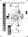 3
3
-
 4
4
-
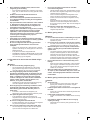 5
5
-
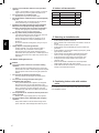 6
6
-
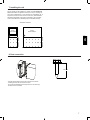 7
7
-
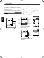 8
8
-
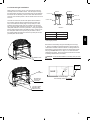 9
9
-
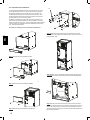 10
10
-
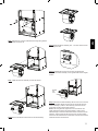 11
11
-
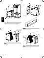 12
12
-
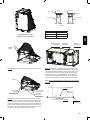 13
13
-
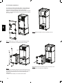 14
14
-
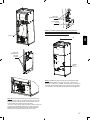 15
15
-
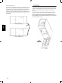 16
16
-
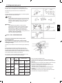 17
17
-
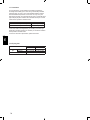 18
18
-
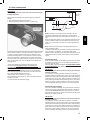 19
19
-
 20
20
-
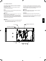 21
21
-
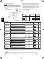 22
22
-
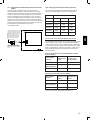 23
23
-
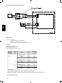 24
24
-
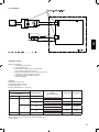 25
25
-
 26
26
-
 27
27
-
 28
28
-
 29
29
-
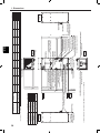 30
30
-
 31
31
-
 32
32
-
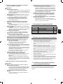 33
33
-
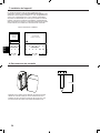 34
34
-
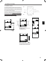 35
35
-
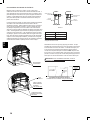 36
36
-
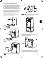 37
37
-
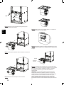 38
38
-
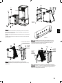 39
39
-
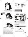 40
40
-
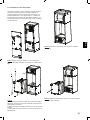 41
41
-
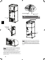 42
42
-
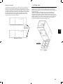 43
43
-
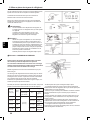 44
44
-
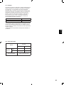 45
45
-
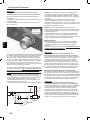 46
46
-
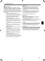 47
47
-
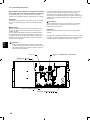 48
48
-
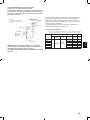 49
49
-
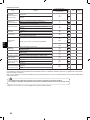 50
50
-
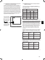 51
51
-
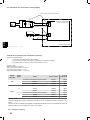 52
52
-
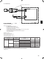 53
53
-
 54
54
-
 55
55
-
 56
56
-
 57
57
-
 58
58


Mitsubishi PVA-A12 P-Series Air Conditioners Manuel utilisateur
- Catégorie
- Climatiseurs split-system
- Taper
- Manuel utilisateur