CommScope PFU-P-C-O-060-02 Manuel utilisateur
- Taper
- Manuel utilisateur

860634349
Two Port PoE Extender
Hardware Manual


Two Port PoE Extender Hardware Manual
This product is copyright © 2017 CommScope, LLC. All Rights Reserved. 3
Table of Contents
Electrical Safety.............................................................................................................. 1
For products that are rack mounted:...................................................................... 1
General................................................................................................................... 2
Sécurité Electrique.......................................................................................................... 3
Pour Les Produits Montés en Rack:....................................................................... 3
Dispositions Générales .......................................................................................... 4
Elektrische Sicherheit ..................................................................................................... 5
Für Geräte, die in einem Rack montiert werden:.................................................... 5
Allgemeines............................................................................................................ 6
CE NOTICE .................................................................................................................... 7
FCC NOTICE.................................................................................................................. 7
Return Product Procedure.............................................................................................. 8
Product user Guide......................................................................................................... 8
1 Introduction........................................................................................... 9
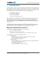
Why Protect Remotely Powered Circuits?...................................................................... 9
2 Package Contents............................................................................... 11
Two Port PoE Extender ................................................................................................ 11
Part Number......................................................................................................... 11
In the Box...................................................................................................................... 11
Also Required (Not Included)........................................................................................ 12
3 Installation........................................................................................... 13
Remove Heat Shield..................................................................................................... 13
Remove Seal Caps and Grommets.............................................................................. 13
Connect Ethernet Cables.............................................................................................. 15
Splitting the Powered Fiber Cable ................................................................................ 16
Cable Split Dimensions........................................................................................ 17
SFP Relationship to Ethernet ports............................................................................... 20
Setting the SFP Connection Speed.............................................................................. 21
Connecting the Powered Fiber Cable to the PoE Extender.......................................... 22
Connecting the Power Strands..................................................................................... 23
Connecting the fiber...................................................................................................... 24
Sealing the PoE Extender............................................................................................. 25
Installing the PoE Extender to Wall or Pole.................................................................. 26
Installing to a Wall................................................................................................ 26
Attaching an Earth Point....................................................................................... 27
Installing to a Pole................................................................................................ 28
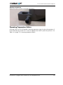
Operating Temperature Advice..................................................................................... 29
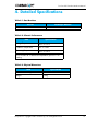
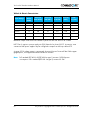
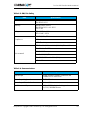
4 Detailed Specifications....................................................................... 31
Copyright, Trademarks and Commercial Disclaimer .................................................... 34

Two Port PoE Extender Hardware Manual
4 This product is copyright © 2017 CommScope, LLC. All Rights Reserved.

Two Port PoE Extender Hardware Manual
This product is copyright © 2017 CommScope, LLC. All Rights Reserved. 1
Safety Notice
In support of the EC directive 2006/95.EC, this notice contains safety information important for the
correct installation and operation of this equipment.
Note, the term SELV (Safety Extra Low Voltage) used in this addendum is defined strictly in
accordance with EN 60950
Electrical Safety
1. This equipment is intended for installation by trained service personnel only.
2. The safety requirements for Information Technology equipment is only valid if the building
installation is in compliance with relevant national or international safety standards and in
accordance with good engineering practice.
3. Remove the DC supply from the supply cable at source before changing supply
connections to this product.
4. For safety requirements it is necessary to connect the earth point on the product to a
reliable earth. This is a discharge path in the event of surges or lightning events on the
supply or Ethernet cables.
5. Unless otherwise specifically stated in the equipment installation manual, all data and
control ports are connected to ES1/SELV/NEC Class 2 conformant circuits inside the
enclosure. To maintain all the ports on the equipment at SELV/NEC Class 2, it is essential
that if any connection is made to any of these ports by other equipment, the other
equipment must maintain its relevant port at ES1/SELV/NEC Class 2.
For products that are rack mounted:
6. For a closed or multi-unit rack assembly, the operating ambient temperature of the rack
environment may be greater than room ambient. Ensure that the equipment environmental
temperature does not exceed the maximum ambient temperature specified by the
manufacturer. Ensure that air flow required for safe operation of the equipment is not
compromised.
7. Mounting of the equipment in the rack must not cause a topple or other mechanical
hazard.
8. Ensure that the accumulative power requirements of equipment installed in the rack do not
exceed the power supply wiring capacity of the rack. Use the equipment nameplate
ratings to establish total requirements.
9. Reliable earthing of rack-mounted equipment should be maintained. Particular attention
should be given to supply connections other than direct connections to the branch circuit
(e.g. use of power strips).

Two Port PoE Extender Hardware Manual
2 This product is copyright © 2017 CommScope, LLC. All Rights Reserved.
General
10. Unless otherwise stated in the equipment manual, there are no user serviceable parts
inside this equipment.
11. If this equipment has a laser, observe the precautions stated in the installation manual.
12. Ultimate disposal of this equipment must be carried out according to relevant national
laws.
13. The equipment should be installed by suitably trained personnel, and installation should
follow good working practice.

Two Port PoE Extender Hardware Manual
This product is copyright © 2017 CommScope, LLC. All Rights Reserved. 3
Consigne de sécurité
À l'appui de la directive de la Commission européenne n° 2006/95.EC, cet avis comporte des
informations capitales pour procéder à une installation et à exploitation en bonne et due forme de
cet équipement de sécurité.
À noter, le terme SELV (Safety Extra Low Voltage) utilisé dans le présent additif est défini le strict
respect des exigences de la norme EN 60950.
Sécurité Electrique
1. Cet équipement doit être installé par du personnel d'entretien formé à la tâche.
2. Les exigences de sécurité équipements de technologies de l'information sont uniquement
valables si l'installation du bâtiment est conforme aux normes de sécurité nationales ou
internationales pertinentes et aux bonnes pratiques d'ingénierie.
3. Veuillez débrancher l'alimentation en c.c. du câble d'alimentation à la source avant de
changer les raccordements d'alimentation à ce produit.
4. Pour les exigences de sécurité, il est nécessaire de connecter le point de mise à la terre au
produit via une terre fiable. Il s'agit d'un trajet de décharge prévu en cas de surtensions
ou de phénomènes de foudre sur l'alimentation ou les câbles Ethernet.
5. Sauf indication contraire figurant dans le guide d'installation de l'équipement, l'ensemble
des données et ports de contrôle sont raccordés à des circuits conformes à la de classe 2
SELV/NEC/ES1 à l'intérieur de l'enceinte. Pour maintenir tous les ports de l'équipement
en classe 2 SELV/NEC/ES1, il est indispensable qu'en cas de raccordement établi vers
l'un quelconque de ces ports par tout autre équipement, ce dernier puisse maintenir son
port correspondant en classe 2 SELV/NEC/ES1.
Pour Les Produits Montés en Rack:
6. Pour un rack fermé ou dispositif à plusieurs racks, la température ambiante de
fonctionnement de l'environnement du rack peut être supérieure à celle ce la température
ambiante. Assurez-vous que la température de l'environnement de l'équipement ne soit
pas supérieure à la température ambiante maximale indiquée par le fabricant. Veiller à
ce que le débit d'air nécessaire au bon fonctionnement de l'équipement ne soit pas
compromis.
7. Le montage du matériel dans le rack ne doit pas provoquer de basculement ni aucun
autre danger mécanique.
8. Veiller à ce que les exigences d'alimentation cumulées de l'équipement installé dans le
rack ne soient pas supérieures à la capacité de câblage d'alimentation du rack. Utilisez
les cotes de la plaque signalétique de l'équipement pour mettre en place toutes les
exigences.
9. Il convient de maintenir une mise à la terre fiable d'équipement monté en rack. Il convient
de faire particulièrement attention aux raccordements d'alimentation autres que ceux
directement en contact avec le circuit de dérivation (p. ex., utiliser des bars
d'alimentation).

Two Port PoE Extender Hardware Manual
4 This product is copyright © 2017 CommScope, LLC. All Rights Reserved.
Dispositions Générales
10. Sauf indication contraire figurant dans le manuel de l'équipement, ce dernier ne
comporte aucune pièce susceptible de réparation par l'utilisateur de l'équipement.
11. Si cet équipement comporte un dispositif laser, veuillez respecter les précautions
indiquées à cet égard dans le guide d'installation.
12. La suppression définitive de cet équipement devra être effectuée conformément aux lois
nationales pertinentes.
13. L'équipement doit être installé par du personnel parfaitement qualifié, et l'installation
devra être conforme aux bonnes pratiques.

Two Port PoE Extender Hardware Manual
This product is copyright © 2017 CommScope, LLC. All Rights Reserved. 5
Sicherheitshinweis
Im Rahmen der EU-Richtlinie 2006/95.EC enthält dieser Hinweis wichtige
Sicherheitsinformationen für die korrekte Installation und den Betrieb dieser Geräte.
Beachten Sie, dass der hier verwendete Begriff SELV (Safety Extra Low Voltage -
Schutzkleinspannung) streng nach EN 60950 definiert ist.
Elektrische Sicherheit
1. Dieses Gerät ist ausschließlich für den Einbau durch geschultes Servicepersonal
vorgesehen.
2. Diese Sicherheitsanforderungen für IT-Ausrüstung sind nur dann gültig, wenn die
Gebäudeinstallation den einschlägigen nationalen und internationalen
Sicherheitsstandards sowie den allgemein anerkannten Regeln der Technik entspricht.
3. Vor Änderung der Versorgungsanschlüsse dieses Geräts muss die DC-Stromversorgung zu
den Versorgungskabeln getrennt werden.
4. Aus Sicherheitsgründen muss der Erdungspunkt des Produktes mit einer zuverlässigen
Erde verbunden werden. Diese dient als Entladungsweg bei Überspannungen oder
Blitzereignissen, die sich auf Versorgungs- oder Ethernet-Kabel auswirken.
5. Sofern im Installationshandbuch nicht ausdrücklich anders vermerkt, sind alle
Datenschnittstellen und Steueranschlüsse mit ES1/SELV/NEC Class 2 konformen
Schaltkreisen im Inneren des Gehäuses verbunden. Damit alle Ports des Geräts mit ES1/
SELV/NEC Class 2 konform bleiben, ist es wichtig, dass die Ports verbundener Geräte
ebenfalls ES1/SELV/NEC Class 2 entsprechen.
Für Geräte, die in einem Rack montiert werden:
6. Bei Einbau in eine geschlossene oder aus mehreren Geräten bestehende Rack-Einheit
kann die Betriebsumgebungstemperatur im Rack höher als die Raumtemperatur sein.
Stellen Sie sicher, dass die Umgebungstemperatur der Geräte die vom Hersteller
angegebene maximale Umgebungstemperatur nicht überschreitet. Achten Sie darauf,
dass der für den sicheren Betrieb des Geräts erforderliche Luftstrom nicht beeinträchtigt
wird.
7. Bei Montage der Geräte in einem Rack darf keine Gefahr durch Kippen oder andere
mechanische Einflüsse entstehen.
8. Stellen Sie sicher, dass der Gesamtleistungsbedarf der im Rack installierten Geräte die
Stromversorgungskapazität des Racks nicht überschreitet. Nutzen Sie die Angaben auf
den Typenschildern, um die Gesamtlast zu ermitteln.
9. Es muss eine zuverlässige Erdung der Rack-Geräte gegeben sein. Besondere
Aufmerksamkeit gilt dabei der indirekten Anbindung an Zweigstromkreise (z. B.
Verwendung von Mehrfachsteckerleisten).

Two Port PoE Extender Hardware Manual
6 This product is copyright © 2017 CommScope, LLC. All Rights Reserved.
Allgemeines
10. Sofern nicht anders im Gerätehandbuch angegeben, enthält dieses Gerät keine zu
wartenden Teile.
11. Wenn dieses Gerät mit einem Laser ausgestattet ist, beachten Sie die in der
Installationsanleitung angegebenen Vorsichtsmaßnahmen.
12. Die Entsorgung dieses Geräts muss nach den einschlägigen nationalen Rechtsvorschriften
erfolgen.
13. Das Gerät muss durch entsprechend geschultes Personal installiert werden. Bei der
Installation ist auf gute Arbeitspraxis zu achten.

Two Port PoE Extender Hardware Manual
This product is copyright © 2017 CommScope, LLC. All Rights Reserved. 7
CE NOTICE
Note: This is a class B product.
FCC NOTICE
Note: This equipment has been tested and found to comply with the limits for a Class B digital
device, pursuant to part 15 of the FCC Rules.
Modifications not expressly approved by the manufacturer could void the user's authority to
operate the equipment under FCC rules.
This Class B digital apparatus complies with Canadian ICES-003.
Cet appareil numerique de la class B est conforme a la norme ICES-003 du Canada

Two Port PoE Extender Hardware Manual
8 This product is copyright © 2017 CommScope, LLC. All Rights Reserved.
Return Product Procedure
If the unit is found to be defective please contact Technical Support via www.commscope.com/
SupportCenter/TechnicalSupport.aspx
Product user Guide
This document details the physical features of the Two Port PoE Extender.

Two Port PoE Extender Hardware Manual
This product is copyright © 2017 CommScope, LLC. All Rights Reserved. 9
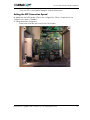
1. Introduction
The PoE Extender is a component of CommScope
®
’s powered fiber cable system, a hybrid optical
fiber/copper cable system for remote powering of network access devices. It is designed to simply
and easily function with the powered fiber cable system to extend the distance of PoE (Power over
Ethernet) enabled devices. The PoE Extender encompasses four primary elements:
1. Environmentally sealed closure
2. Electrical power management
3. Circuit protection electronics
4. Optical to electrical Media Conversion
When coupled with any standard NEC Class II 48V DC power supply CommScope’s Powered
Fiber Cable system can power and communicate with PoE standard devices at far greater
distances than "category style" copper cabling systems which are typically limited to 90 meters,
and still meet NEC Class II and SELV standards, eliminating the need for qualified electricians
during installation.
The PoE Extender also contains circuit protection and DC/DC conversion electronics which
automatically condition electrical voltage to the correct level needed for PoE input to the device
under load (such as a small cell, high definition security camera, Wi-Fi hot spot, etc).
Why Protect Remotely Powered Circuits?
Long length DC low voltage electrical systems are at increased risk of:
• AC cross from high voltage cables
• Higher current in the event of a short circuit
• Strong electrical surges due to lightning strikes or other EM events in close vicinity
The PoE Extender provides two levels of electrical protection:
5. Primary Protection:
• Metal oxide varistors - operates for slower surges as well as fast surges
• Protects both differential and common mode
• MOV components rated to 4.5kA
6. Secondary Protection:
• Transient voltage suppressors - works at relatively low/slow surges, adds an extra
layer of protection against voltage spikes
• Protects differential mode only
• Prevents the voltage from rising above 80-100V

Two Port PoE Extender Hardware Manual
10 This product is copyright © 2017 CommScope, LLC. All Rights Reserved.
Additional protection elements include:
• Cross-polarity protection to simplify installation - the circuit will work regardless of the
input polarity
• AC cross protection:
• 4A non replaceable fuses
• No exposed high voltage pads
• High power inductors used as coordinating elements to maximize energy efficiency
• Sealed enclosure for environmental protection

Two Port PoE Extender Hardware Manual
This product is copyright © 2017 CommScope, LLC. All Rights Reserved. 11
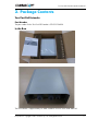
2. Package Contents
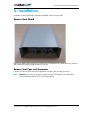
Two Port PoE Extender
Part Number
The part number for the Two Port PoE Extender is PFU-P-C-O-060-02
In the Box
The PoE Extender is supplied ready for cable installation with the solar shield attached.

Two Port PoE Extender Hardware Manual
12 This product is copyright © 2017 CommScope, LLC. All Rights Reserved.
Also Required (Not Included)
• 3mm and 4mm Allen key
• 2 x Standard 100Base-X or1000Base-X SFP transceiver (Singlemode or Multimode)
• 25mm Torque or adjustable spanner/wrench
• 30mm Torque or adjustable spanner/wrench
• Posidriv screwdriver
• Silicone grease
• Loctite 222
• Knife for splitting the fiber cable
• 12 AWG or 2mm diameter wire stripper for 12 AWG cable
• 16 AWG or 1.2mm wire diameter stripper for the 16 AWG cable
• Fastenings for wall/pole mounting

Two Port PoE Extender Hardware Manual
This product is copyright © 2017 CommScope, LLC. All Rights Reserved. 13
3. Installation
Installation of the PoE Extender should be completed in the following order.
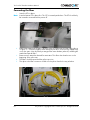
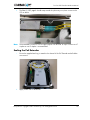
Remove Heat Shield
Remove the 4 bolts attaching the heat shield to the PoE Extender with a 3mm Allen key. Slide the
heat shield off the retaining lugs and put to one side.
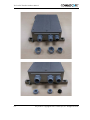
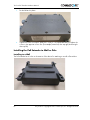
Remove Seal Caps and Grommets
Unscrew the caps and then remove the grommets from the 3 pass through connectors.
Note: Do not unscrew any of the pass throughs from the PoE Extender. These have been
factory fitted and sealed to the correct torque setting.

Two Port PoE Extender Hardware Manual
14 This product is copyright © 2017 CommScope, LLC. All Rights Reserved.

Two Port PoE Extender Hardware Manual
This product is copyright © 2017 CommScope, LLC. All Rights Reserved. 15
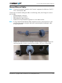
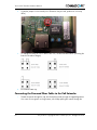
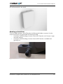
Connect Ethernet Cables
CommScope recommend installing the cables in the following order, when facing the connector
pass throughs:
1. Left hand ethernet connection
2. Right hand ethernet connection
3. Fiber and power cable connection
4. Thread the seal cap and ethernet grommet on to the cable as below.
5. Connect one of the RJ45 to the PoE Extender to the left hand pass through, with the lock
clip facing upwards, as below. Note the Ethernet cable is still loose in the grommet.
Note: Connection from the PoE Extender to the Customer’s equipment should be via a Cat 5E /
Cat 6 screened (STP) cable.
Note: If using a pre-terminated ethernet cable it may be necessary to remove the boot. Some
connectors may require cutting the cable and re-terminating after threading the cable
through the grommet.

Two Port PoE Extender Hardware Manual
16 This product is copyright © 2017 CommScope, LLC. All Rights Reserved.
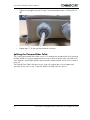
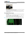
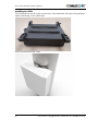
6. Tighten the cap against the pass through. The recommended torque is 2.50Nm (22.1in
lbf).
7. Note that the grommet is now tightened against the cable.
8. Repeat steps 1-7 for the right hand ethernet connection.
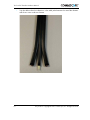
Splitting the Powered Fiber Cable
The CommScope Powered Fiber Cable consists of 2 copper power threads and a third containing
the fiber threads. You need to separate the three cores to allow the power to be connected to the
screw terminals, and the fiber thread to be connected to a fiber terminal, which is then inserted in
to the SFP.
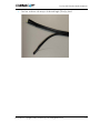
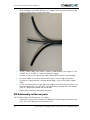
The Powered Fiber Cable is design to access using only a typical pair of wire strippers and,
optionally, a wire cutter or snip. To split the cable successfully, follow this process:
La page est en cours de chargement...
La page est en cours de chargement...
La page est en cours de chargement...
La page est en cours de chargement...
La page est en cours de chargement...
La page est en cours de chargement...
La page est en cours de chargement...
La page est en cours de chargement...
La page est en cours de chargement...
La page est en cours de chargement...
La page est en cours de chargement...
La page est en cours de chargement...
La page est en cours de chargement...
La page est en cours de chargement...
La page est en cours de chargement...
La page est en cours de chargement...
La page est en cours de chargement...
La page est en cours de chargement...
-
 1
1
-
 2
2
-
 3
3
-
 4
4
-
 5
5
-
 6
6
-
 7
7
-
 8
8
-
 9
9
-
 10
10
-
 11
11
-
 12
12
-
 13
13
-
 14
14
-
 15
15
-
 16
16
-
 17
17
-
 18
18
-
 19
19
-
 20
20
-
 21
21
-
 22
22
-
 23
23
-
 24
24
-
 25
25
-
 26
26
-
 27
27
-
 28
28
-
 29
29
-
 30
30
-
 31
31
-
 32
32
-
 33
33
-
 34
34
-
 35
35
-
 36
36
-
 37
37
-
 38
38


CommScope PFU-P-C-O-060-02 Manuel utilisateur
- Taper
- Manuel utilisateur
dans d''autres langues
Documents connexes
Autres documents
-
Arris XB7 Manuel utilisateur
-
Wiremold 4ATCP2CRBK Guide d'installation
-
ATEN KE8952 Guide de démarrage rapide
-
ATEN KE6920T Guide de démarrage rapide
-
ATEN KE9952 Guide de démarrage rapide
-
ATEN KE6912T Guide de démarrage rapide
-
Foundry Networks FES12GCF Guide d'installation
-
Motorola EX-3524 Guide d'installation
-
Tenda TEF1126P-24-410W Guide d'installation
-
Tripp Lite NGS8C2POE Le manuel du propriétaire