Bosch SGX68U55UC/A3 Guide d'installation
- Taper
- Guide d'installation

9001 (9)
Installation Instructions
Notice d’installation


1
Important Safety Instructions
To avoid possible injury or property damage,
OBSERVE ALL WARNINGS AND CAUTIONS.
These instructions are intended for use by qualified
installers only. The dishwasher must be installed by
a qualified service technician or installer.
x In addition to these instructions, the dishwasher
shall be installed to meet all electrical and
plumbing codes and ordinances (both national
and local).
Read these installation instructions completely
and follow them carefully. They will save you time
and effort and help to ensure safety and optimum
dishwasher performance.
IMPORTANT
x The dishwasher drain hose must be installed
with a portion of it at least 20Ǝ (508 mm) off the
cabinet floor; otherwise the dishwasher may not
drain properly.
x This dishwasher is intended for indoor
residential use only, and should not be used in
commercial food service establishments.
x NEW INSTALLATION - If the dishwasher is a
new installation, most of the work must be done
before the dishwasher is moved into place.
x REPLACEMENT - If the dishwasher is replacing
another dishwasher, check the existing
dishwasher connections for compatibility with
the new dishwasher, and replace parts as
necessary.
x This appliance has been found to be in
compliance with CAN/CSA-C22.2 No. 167/UL
749.
It is the responsib
ility of the owner a
nd the
insta
ller to determine if additional requirements
and standards apply in specific installations.
x Not for outdoor use.
Inspect the Dishwasher
After unpacking the dishwasher and prior to
installation, thoroughly inspect the dishwasher for
possible freight or cosmetic damage. Report any
damage immediately. Cosmetic defects must be
reported within 30 days of installation.
NOTE: Do not discard any bags or items that come
with the original package until after the entire
installation has been completed.

2
WARNING
Avoiding General Hazards
Do not use the dishwasher until it is completely
installed. When opening the door on an uninstalled
dishwasher, carefully open the door while
supporting the rear of the unit. Failure to follow this
warning can cause the dishwasher to tip over and
result in serious injury.
Before installing the “L”-shaped supplied countertop
mounting brackets (select models), decide which
method will be used to secure the dishwasher into
its opening. Once these mounting brackets are
installed on the dishwasher, removing them is
difficult and will damage the mounting brackets and
the dishwasher.
In some conditions, hydrogen gas can form in a hot
water system that has not been used for weeks.
Hydrogen gas is explosive.
Before filling a dishwasher from a system that has
been off for weeks, run the water from a nearby
faucet in a well ventilated area until there is no
sound or evidence of gas.
Temperatures required for soldering and sweating
will damage the dishwasher’s base and water inlet
valve. If plumbing lines are to be soldered or
sweated, keep the heat source at least 6Ǝ (152.4
mm) away from the dishwasher’s base and water
inlet valve.
Removing any cover or pulling the dishwasher from
the cabinet can expose hot water connections,
electrical power and sharp edges or points. Handle
with care.
Avoiding Electrical Shock/Fire Hazards
Do not allow the electrical and water supply lines to
touch. Separate channels are provided under the
dishwasher.
Do not work on an energized circuit. Doing so could
result in serious injury or death. Only qualified
electricians should perform electrical work. Do not
attempt any work on the dishwasher electric supply
circuit until you are certain the circuit is de-
energized.
Make sure electrical work is properly installed.
There should be no loose electrical connections.
Ensure all electrical connections are properly made.
The customer has the responsibility of ensuring that
the dishwasher electrical installation is in
compliance with all national and local electrical
codes and ordinances. The dishwasher is designed
for an electrical supply of 120V, 60 Hz, AC,
connected to a dishwasher-dedicated, properly
grounded electrical circuit with a fuse or breaker
rated for 15 amps. Electrical supply conductors
shall be a minimum #14 AWG copper only wire
rated at 75°C (167°F) or higher.
This appliance must be connected to a grounded
metal, permanent wiring system, or an equipment-
grounding conductor must be run with the circuit
conductors and connected to the equipment-
grounding terminal or lead on the appliance. Do not
use extension cords.
Avoiding Electrical Shock/Fire Hazards
Do not perform any work on a charged hot water
line. Serious injury could result. Only qualified
plumber should perform plumbing work. Do not
attempt any work on the dishwasher hot water
supply plumbing until you are certain the hot water
supply is shut off.
Do not over tighten the 90° elbow. Doing so may
damage the water inlet valve and cause a water
leak.
Temperatures required for soldering and sweating
will damage the dishwasher’s water inlet valve. If
plumbing lines are to be soldered or sweated, keep
the heat source at least 6Ǝ (152.4 mm) away from
the dishwasher’s water inlet valve.
Check local plumbing codes for approved plumbing
procedures and accessories. All plumbing should
be done in accordance with national and local
codes.
These instructions depict an installation method for
stainless steel braided hose or PEX hot water
supply lines. If using copper tubing or other material
for water supply, defer to a licensed plumber for
proper installation.

3
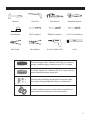
Tools and Materials Needed
Ha
mmer Hole Saw Pipe Wrench Adjustable Wrench
Tape Measure Slot Screwdriver Phillips Screwdriver Torx T-20 Screwdriver
Wire Cutter Wire Stripper Ø 2 mm (1/16 in) Drill Level
Electrical Supply Cable - Minimum #14 AWG, 2 conductor, 1
ground, insulated copper conductors rated 75°C or higher
Hot Water Supply Line - Minimum 3/8Ǝ O.D. copper tubing or
metal braided dishwasher supply line
Shut-off valve and fittings appropriate for hot water supply
line (copper tubing/compression fitting, or braided hose
UL listed conduit connector or strain relief is required if you
attach the field wiring directly to the terminal block

4
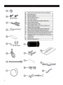
Materials Supplied
4x16mm 4x16mm
4x15mm

5
Enclosure Requirements
WARNING
Avoid Scalding or Electrical Shock Hazard!
Make sure the water supply and electrical supply are
shut off before installation or service.
NOTE: This dishwasher is designed to be enclosed on
the top and both sides by standard residential kitchen
cabinetry.
Select a location as close to the sink as possible for
easy access to water supply and drain lines.
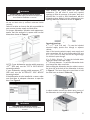
For proper dishwasher operation and appearance,
ensure that the enclosure is square and has the
dimensions shown in Figure 1.
Figure 1
NOTE: If your dishwasher opening width measures
>23
5/8
Ǝ (600 mm) use the TOP or SIDE MOUNT
mounting methods.
If your dishwasher opening width measures 23
5/8
Ǝ
(600 mm) use the ALTERNATE SIDE MOUNT
mounting method.
If the dishwasher is to be installed in a corner, make
sure that there is adequate clearance to open the
door. See Figure 2.
Figure 2
WARNING
Avoid Electrical Shock/Fire Hazard!
Do not allow the electrical and water supply lines
to touch.
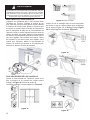
After locating the proper place for your new
dishwasher, you will need to create any required
openings to allow for passage of the water, drain and
electrical line. In order to avoid interference with the
dishwasher when sliding it into the cabinet, place your
openings within the dimensions shown in Figure 3.
Figure 3
Required Openings:
4
3/4
Ǝ x 2
3/8
Ǝ (120 x 60 mm) - To pass the included
electrical supply junction box through to adjacent
cabinet.
Note: If the incoming electric supply, water supply and
drain connections are all in the same cabinet, the one
4
3/4
Ǝ x 2
3/8
Ǝ (120 x 60 mm) hole will be large enough
for all three to pass through.
4Ǝ x 2Ǝ (100 x 50 mm) - To pass the included water
supply line toward the water supply.
1
1/4
Ǝ (32 mm) diameter - To pass the dishwasher drain
hose toward the drain connection.
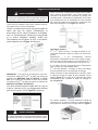
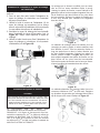
Before sliding the dishwasher into the cabinet, remove
the hose clip at the back of the dishwasher as shown
in Figure 4. The hose clip may be used later to hold
the drain hose as shown in Figure 10.
Figure 4
In select models, remove the rubber apron on top of
the dishwasher and set aside for later use (Figure 5).
Figure 5

6
Electrical Preparation
WARNING
Avoid Electrical Shock Hazard!
Do not work on an energized circuit. Doing so could
result in serious injury or death. Only qualified
electricians should perform electrical work. Do not
attempt any work on the dishwasher electric supply
circuit until you are certain the circuit is de-energized.
WARNING
Avoid Fire Hazard!
Make sure electrical work is properly installed. Only
qualified electricians should perform electrical work.
Electrical Supply
The customer has the responsibility of ensuring that
the dishwasher electrical installation is in
compliance with all national and local electrical
codes and ordinances. The dishwasher is designed
for an electrical supply of 120V, 60 Hz, AC,
connected to a dishwasher-dedicated, properly
grounded electrical circuit with a fuse or breaker
rated for 15 amps. Electrical supply conductors
shall be a minimum #14 AWG copper wire rated at
75°C (167°F) or higher.
WARNING
Avoid Fire Hazard!
Make sure there are no loose electrical connections.
Make sure all electrical connections are properly made.
Grounding Instructions
The dishwasher must be properly grounded before
operating. This appliance must be connected to a
grounded metal permanent wiring system or an
equipment grounding conductor must be run with
the circuit conductors and connected to the
equipment grounding terminal or lead on the
dishwasher. Make sure that the dishwasher is
connected to a suitable ground in compliance with
all local codes or, in the absence of a local code,
with the NATIONAL ELECTRICAL CODE in the
United States or the CANADIAN ELECTRIC CODE
C22.1-latest edition in Canada as well as any
provincial/state or municipal or local codes that
apply.
Dishwasher Electrical Rating
Volts Hertz Amperes Watts
120 60 12 1,300 (max)
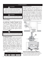
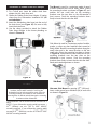
Electrical Connection
The dishwasher electrical supply junction box (P) and
dedicated receptacle must be mounted in an
accessible cabinet adjacent to the dishwasher (do not
mount the junction box or receptacle behind the
dishwasher). You will need a 4
3/4
Ǝ x 2
3/8
Ǝ (120 x 60
mm) opening through the cabinet in order to pass the
junction box through (see Figure 6). If the opening is
made through wood, sand it smooth. If the opening is
made through metal, use the included protective
grommet (I) or other approved method to protect
wiring from damage. Use the four screws included (or
appropriate fastener) in the parts bag to securely
mount the junction box so that it can be easily
accessed (see Figure 6). The electrical supply can be
connected in two ways:
Figure 6
Method A - Three prong plug and receptacle
Use the included three-prong plug and junction box to
connect to a dedicated household receptacle. Make sure
the household receptacle meets the electrical supply
requirements as well as national and local codes.
Figure 7

7
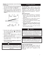
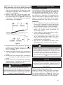
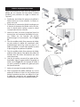
Method B - To permanently connect to household
or field wiring
1. Remove the dishwasher electrical supply junction
box cover and connect to the power supply cord
from the house installation (see Figure 7).
2. Remove 2Ǝ to 3Ǝ (51 – 76 mm)
of the outer
ca
sing of the household or field supply wiring as
shown in Figure 8. Remove 3/8Ǝ to 1/2Ǝ (10 – 13
mm)
of the insula
tion from each wire as shown in
Figure 8
.
Fi
gure 8
3. Insert the bare copper or green wire(ground) to
the “G” ground connection “ ” of the termina
l
block a
nd securely tighten the terminal block
screw (see Figure 7
).
4.
Insert the white (neutral) wire to the “N
”
connection of
the terminal block and securely
tighten the terminal block
screw.
5.
Insert the black (hot) wire to the “L” connection of
the terminal block and securely tigh
ten the
term
inal block screw.
6. Check all electrical connections to make sure
they are secure and then atta
ch the junction box
cov
er with the 4 screws
.
WARNING
Avoid Electrical Shock Hazard!
To avoid possible injury or property damage, care
should be exercised when the dishwasher is installed
or removed to reduce the likelihood of damage to the
power cord.
Inlet Water Connections
Hot Water Supply
The hot water heater should be set to deliver
approximately 120° F (49° C) water to the
dishwasher. Water that is too hot can cause some
detergents to lose effectiveness. Lower water
temperatures will increase run times. The hot water
supply pressure must be between 15 - 145 psi (1 -
10 bar).
IMPORTANT NOTES:
x If using a solder joint instead of a compression
fitting, be sure to make all solder connections
before connecting the water supply line to the
dishwasher.
x Make sure there are no sharp bends or kinks in
the water line that might restrict water flow.
x Always use the appropriate seal when making
plumbing connections.
x Before connecting the water supply line to the
dishwasher, flush the incoming water line for
approximately 5 minutes to clear any foreign
material.
x Turn on the water supply and check for leaks
after connections are made.
WARNING
Avoid Scald Hazard!
Do not perform any work on a charged hot water line.
Serious injury could result. Only qualified plumbers
should perform plumbing work. Do not attempt any work
on the dishwasher hot water supply plumbing until you
are certain the hot water supply is shut off.
CAUTION
Temperatures required for soldering and sweating will
damage the dishwasher. If plumbing lines are to be
soldered or sweated, keep the heat source at least 6
inches (152.4 mm) away from the dishwasher.
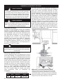
Wa
ter Supply Shut Off Valve
Install an easily accessible shut-off valve (not
supplied) in the hot water supply line, as shown in
Figure 9. All solder connections must be made
before the water line is connected to the
dishwasher.

8
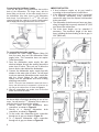
Connecting the Hot Water Supply
There are two plastic corrugated hoses that exit the
back of the dishwasher. The larger hose, with the
brass fitting on the end, is the water supply hose to
the dishwasher (the other hose is the dishwasher
drain hose). You will need a 3Ǝ x 1
3/4
Ǝ (76 x 45 mm)
opening through the cabinet to pass the dish-washer
water supply line through toward the shut off valve.
Figure 9
To connect the hot water supply:
1. Assemble the water supply adaptor fitting (H)
from the parts bag onto the dishwasher water
supply hose. Th
is connection does not require
T
eflon brand tape
2. Pass the dishwasher water supply line wi
th
a
ttached adaptor through the opening toward the
water shut off valve. Take care not to allow the
hose to kink or twist behind the dishwa
sher.
3
. Connect the dishwasher water supply line wi
th
a
daptor to the water shut off valve. You will
need
to use a
n approved dishwasher water supply li
ne
w
ith the correct fittings for this connection.
Always use the appropriate seal when making
plum
bing connections.
NOTE: The end of the dishwasher water inlet hose is
heavy and will need to be supported. It is best to lay
the end on the cabinet floor as shown in Figure 9
.
4. After all connections are made, turn on the hot
water and check for leaks.
Drain Connections
The dishwasher drain hose may be connected to
the house-hold or field drain plumbing in one of four
ways. You will need a 1
1/4
" diameter hole in order to
pass the drain hose through the cabinet.
1. Directly under the sink dishwasher drain
connection, as shown in Figure 11.
2. Directly to a disposer dishwasher drain
connection, as shown in Figure 12.
3. To the under sink dishwasher drain connection
through an air gap, as shown in Figure 13.
4.
To a disposer dishwasher drain connecti
on
throug
h an air gap, as shown on Figure 14
.
I
MPORTANT NOTES:
x If local ordinance require an air gap, install it
according to the manufacturer’s instructions.
x If the dishwasher drain hose is to be connected
to a disposer dishwasher drain connection,
remove the plug from the disposer’s dishwasher
drain connection.
x The dishwasher drain hose must have one place
along its length that is securely attached 20Ǝ (508
mm) above the cabinet floor.
x The drain hose length can be extended if
necessary. The maximum length of the drain
hose, including the hose leading to the air gap, is
150Ǝ (3800 mm).
Figure 10
Figure 11 Figure 12
Figure 13 Figure 14

9
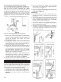
Installation of Rubber Drain Hose Adaptor
For a large port, use the drain hose as it is.
1. For a small port, insert the rubber drain hose
adaptor into the drain hose end.
2. Obtain the Rubber Drain Hose Adaptor (J) spring
clamp from the Dishwasher Installation Kit (do
not substitute).
3. Insert the dishwasher drain hose into the end of
the drain hose (see Figure 15). Be sure to fully
insert the drain hose.
4. Use the clamp provided to attach the Rubber
Drain Hose Adaptor to the house plumbing as
shown in Figure 16.
Figure 15
Figure 16
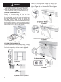
Installation of Mounting Brackets
CAUTION
Before installing the supplied countertop mounting
brackets, decide which method of securing the
dishwasher into its enclosure will be used. Once the
mounting brackets are installed on the dishwasher,
removing them is difficult and will damage the mounting
brackets and the dishwasher.
The dishwasher can be secured into its enclosure in 3
ways:
NOTE: If your dishwasher opening width measures >
23
5/8
Ǝ (600mm) use the TOP or SIDE MOUNT
mounting methods. If your dishwasher opening width
measures 23
5/8
Ǝ (600 mm) use the ALTERNATE SIDE
MOUNT mounting method.
Top Mount is used for countertops made of wood
or other materials that can be easily drilled. Orient
the mounting brackets as shown in Figure 17, and
position the two small tabs on the mounting
brackets over the two slots on the dish-washer’s
front corners. Push the mounting brackets down
firmly to insert the tabs into the slots
Figure 17
Side Mount is used for countertops made of marble,
granite, or other very hard materials that cannot be
easily drilled. Bend the mounting brackets along the
small holes and in the same direction as the two
small tabs. Orient the mounting brackets as shown
in Figure 18, and position the two small tabs on the
mounting brackets over the two slots on the
dishwasher’s front corners. Push the mounting
brackets down firmly to insert the tabs into the slots.
Bend perforated edge down as shown.
Figure 18
Alternate Side Mount for opening 23
5/8
Ǝ (600 mm).
Insert a side mount force distributor (M) in each side
as shown in Figure 19.
Figure 19

10
WARNING
Avoid Tip Over Hazard!
Do not use the dishwasher until it is completely installed.
When opening the door on an uninstalled dishwasher,
carefully open the door while supporting the rear of the unit.
Failure to follow this warning can result in serious injury.
LEVELING THE DISHWASHER
The unit should now be ready to slide into the cabinet
opening. To avoid scratching the floor, use floor
protection and caution when sliding the dishwasher into
the cabinet. Make sure that the hoses and cords do not
bunch up behind the unit or kink as you slide the unit
back. Make certain to slide the unit into place before
raising the leg levelers. Level the dishwasher horizontally
by turning feet clockwise to raise or counter-clockwise to
lower front of the unit. Level the dishwasher vertically by
turning center screw to raise or lower the back.
)LJXUH
SECURING THE DISHWASHER
Center the dishwasher in the opening before securing
it to your cabinet or countertop as shown in Figure 21.
Remove the top cutlery rack as shown in Figure22.
Figure 22 PRGHOGHSHQGHQW
Drive the mounting screws through the holes in the
mounting brackets as shown for Top (Figure 23), Side
Mount (Figure 24) and Alternate Side Mount (Figure
25).
Figure 23
Figure 24
Figure 25
Figure 21

11
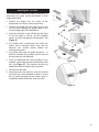
Attaching the Toe Panel
Your dishwasher comes with either a two-piece or
three-piece toe panel (model dependent) to allow
height adjustment.
1. Position the slotted rear toe panel on the
dishwasher first. Allow it to rest on the floor.
2. Position the mating front toe panel on top of the
rear toe panel allowing the angled edge to rest
on the mating edge of the dishwasher.
3. Drive the two black screws (B) through the holes
in the toe panel to secure. Use the supplied
screws to avoid damaging the dishwasher. See
Figure 26.
4. For models with a three-piece toe panel, the
rubber apron removed earlier may now be
attached and should remain behind the
outermost toe panel.
5. For models with outer toe panel (3rd piece - L)
slide the brackets (K) provided, into the slots of
the toe panel you just attached.
6. Once you determine the correct position for the
brackets, remove the bracket and bend the metal
tab. See Figure 27. This ensures that the toe
panel will not slide in further than you need.
7. Re-insert the brackets.
8. Attach the outer toe panel (L) onto the brackets
and drive the screws provided in place to secure
the toe panel ensuring that the rubber apron is
completely hidden behind the outer toe panel.
Figure 26
Figure 27

12
Customer Service
Your dishwasher requires no special care other
than that described in the Care and Maintenance
section of the Use and Care Manual. If you are
having a problem with your dishwasher, before
calling for service please refer to the Self Help
section in the Use and Care Manual. If service is
necessary, contact your dealer or installer or an
authorized service center.
Do not attempt to repair the appliance yourself. Any
work performed by unauthorized personnel may
void the warranty. If you are having a problem with
your dishwasher and are not pleased with the
service you have received, please take the following
steps (in the order listed below) until the problem is
corrected to your satisfaction:
1. Contact your installer or the Authorized Service
C
ontractor in your ar
ea.
2.
E-mail us. See your Use and Care Manual for
instructions.
3. Write us at the address below
:
BSH
Home Appliances Corporation
1901 Main Street
Irvine, CA 92614
4. Call us at the Customer Service phone number:
1-800-944-2904
Please be sure to include (if you are writing), or
have available (if you are calling), the following
information:
x Model number
x Serial number
x Date of original purchase
x Date the problem originated
x Explanation of the problem
x Daytime phone number where you can be
reached.
Please make a copy of your invoice and keep it with
this manual. The customer must show proof of
purchase to obtain warranty service.

13
Consignes de sécurité importantes
Afin d’éviter toute possibilité de blessures ou de
dommages matériels VEUILLEZ OBSERVER
TOUS LES AVERTISSEMENTS ET PRÉCAU-
TIONS.
Ces instructions sont destinées uniquement à
l’usage des installateurs qualifiés. L’installation du
lave-vaisselle doit être effectuée par un technicien
de maintenance ou un installateur qualifié.
x Outre ces instructions, l’installation du lave-linge
doit être effectuée conformément à tous les co-
des et ordonnances nationaux et locaux en ma-
tière d’électricité et de plomberie.
Lire cette notice d’installation entièrement et s’y
conformer scrupuleusement. Cette notice vous
permettra d’économiser du temps et des efforts et
vous aidera à assurer la sécurité et l’efficacité opt-
male de votre lave-vaisselle.
IMPORTANT
x Le tuyau de vidange du lave-vaisselle doit être
installé de façon à ce qu’une partie du tuyau soit
à 20 pouces (508 mm) minimum au-dessus du
plancher de l’armoire ; autrement, le lave-
vaisselle risque de ne pas se vidanger correc-
tement.
x Ce lave-vaisselle est destiné à un usage do-
mestique uniquement et ne doit pas être utilisé
par des établissements de service alimentaire
commerciaux.
x NOUVELLE INSTALLATION - Si le lave-
vaisselle est installé pour la première fois, la
plupart des travaux d’installation doivent être
réalisés avant que l’appareil ne soit mis en pla-
ce.
x REMPLACEMENT - Si le lave-vaisselle est ins-
tallé en remplacement d’un autre, vérifier les
raccordements du lave-vaisselle existant pour
vous assurer qu’ils sont compatibles à ceux du
nouveau lave-vaisselle, et remplacer les pièces
qui doivent l’être.
x Cet appareil a été trouvé conforme à la norme
CAN/CSA-C22.2 n° 167/UL 749. Le propriétaire
et l’installateur ont la responsabilité de détermi-
ner si des exigences et normes supplémentai-
res s’appliquent à des installations spécifiques.
x Non pour l’usage en extérieur.
Inspection du lave-vaisselle
Après avoir déballé le lave-vaisselle et avant son
installation, examinez-le attentivement pour déceler
d’éventuels dégâts esthétiques ou liés au transport.
Signaler immédiatement tout dégât.
Les défauts esthétiques doivent être signalés dans
un délai de 30 jours à compter de l’installation.
REMARQUE : ne pas jeter les sacs ou les éléments
contenus dans l’emballage d’origine avant d’avoir
complètement terminé l’installation du lave-
vaisselle.

14
AVERTISSEMENT
Prévention des dangers d’ordre général
Ne pas utiliser le lave-vaisselle tant que l’installation
n’est pas complètement terminée. Pour ouvrir la porte
d’un lave-vaisselle dont l’installation n’est pas termi-
née, agir avec prudence et en soutenant la partie ar-
rière de l’appareil. Le non respect de cetS avertisse-
ment peut entraîner le basculement du lave-vaisselle
et provoquer de graves blessures.
Avant d’installer les pattes de fixation pour comptoir
en « L » (certains modèles) fournies, déterminer la
méthode à utiliser pour fixer solidement le lave-
vaisselle dans l’ouverture. Une fois les pattes de fixa-
tion installées sur le lave-vaisselle, il sera difficile de
les retirer sans les abîmer ainsi que le lave-vaisselle.
Sous certaines conditions, un chauffe-eau peut pro-
duire de l’hydrogène s’il n’a pas été utilisé pendant
plusieurs semaines. L’hydrogène est un gaz explosif.
Avant de remplir un lave-vaisselle en utilisant de l’eau
fournie par un chauffe-eau qui n’a pas fonctionné
pendant plusieurs semaines, faites couler l’eau d’un
robinet situé à proximité, dans un endroit bien aéré,
jusqu’à ce qu’il n’y ait plus de bruit et qu’aucun déga-
gement de gaz ne se manifeste de façon visible.
Les températures nécessaires pour souder et exsuder
risquent d’endommager la base et le robinet d’arrivée
d’eau du lave-vaisselle. Si certains tuyaux doivent être
soudés ou exsudés, maintenir la source de chaleur au
à 6 pouces (152,4 mm) minimum de distance de la
base et du robinet d’arrivée d’eau du lave-vaisselle.
Le retrait d’une paroi ou le fait de tirer le lave-
vaisselle hors de son encastrement peut exposer les
conduites d’eau chaude, l’alimentation électrique et
certains rebords et angles tranchants. Effectuer ces
manœuvres avec prudence.
Prévention des dangers de choc
électrique et d’incendie
Les câbles électriques et les tuyaux d’alimentation
d’eau ne doivent pas entrer en contact les uns avec
les autres. Des canaux indépendants sont prévus à
cet effet sous le lave-vaisselle.
Ne pas tenter d’intervenir sur un circuit sous tension.
Vous risquez autrement des blessures graves, voire la
mort. Seuls les électriciens qualifiés doivent effectuer
des travaux sur l’installation électrique. Ne pas tenter
d’intervenir sur le circuit électrique du lave-vaisselle à
moins d’être certain que celui-ci est hors tension.
Vérifier que l’installation électrique est correctement
réalisée. Il ne doit y avoir aucun raccordement électri-
que lâche. Vérifier que tous les branchements électri-
ques sont correctement effectués.
Le client a la responsabilité de vérifier que l’installation
électrique du lave-vaisselle est conforme à tous les
codes et ordonnances électriques nationaux et locaux.
Le lave-vaisselle a été conçu pour fonctionner avec
une alimentation électrique en courant alternatif de
120 volts, 60 Hz, connectée à un circuit électrique
correctement mis à la terre, adapté au lave-vaisselle,
avec protection par fusible ou disjoncteur d’une puis-
sance de 15 ampères. Les conducteurs d’alimentation
électrique doivent être uniquement en fil de cuivre de
calibre 14AWG minimum pour une température nomi-
nale de 75°C (167°F) ou plus.
Cet appareil doit être raccordé à un système de câ-
blage en métal permanent mis à la terre ou un
conducteur de terre de l’appareil doit être utilisé avec
les conducteurs de circuit et raccordé à la borne ou au
fil de terre du lave-vaisselle. Ne pas utiliser de rallon-
ge.
Prévention des dangers d’ébouillantage
et liés aux travaux de plomberie
Ne pas tenter de travailler sur une conduite d’eau
chaude chargée. De graves blessures pourraient sur-
venir. Seuls les plombiers qualifiés doivent effectuer
des travaux sur la tuyauterie. Ne pas tenter
d’intervenir sur la tuyauterie d’alimentation d’eau
chaude du lave-vaisselle tant que vous n’êtes pas
certain que l’alimentation d’eau chaude est coupée.
Ne pas serrer le raccord coudé à 90° à l’excès. Vous
risquez en effet d’endommager le robinet d’arrivée
d’eau et de provoquer une fuite.
Les températures requises pour les opérations de
soudure et d’exsudation risquent d’endommager le
robinet d’arrivée d’eau du lave-vaisselle. Si certains
tuyaux doivent être soudés ou exsudés, maintenir la
source de chaleur à 6 pouces (152,4 mm) minimum
de distance du robinet d’arrivée d’eau du lave-
vaisselle.
Consulter les codes de plomberie locaux pour connaî-
tre les procédures et accessoires de plomberie ap-
prouvés. Tous les travaux de plomberie doivent être
réalisés conformément aux codes nationaux et locaux.
Ces instructions décrivent la méthode d’installation
des flexible stressés en acier inoxydable ou des
conduites d’eau chaude en polyéthylène réticulé. Si
vous utilisez des tubes en cuivre ou d’un matériau
différent pour l’alimentation en eau, faire appel à un
plombier autorisé afin d’assurer une installation adé-
quate.

15
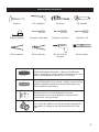
Outils et pièces nécessaires
Marteau Scie cylindrique Clé à tube Clé ajustable
Ruban à mesurer Tournevis à lame plate Tournevis cruciforme Tournevis T-20
Pince coupante Pince à dénuder Ø 2 mm (1/16 in)
Perceuse
Niveau à bulle
Câble d’alimentation électrique - calibre de 14 AWG mini-
mum, 2 conducteurs, 1 mise à la terre, conducteurs en cuivre
isolé à une température nominale de 75° C ou plus.
Tuyau d’alimentation d’eau chaude - tube de cuivre de 3/8 po
minimum (diamètre extérieur) ou tuyau d’alimentation pour
lave-vaisselle en métal tressé.
Robinet d’arrêt et raccords appropriés pour tuyau
d’alimentation d’eau chaude ((tube de cuivre/raccord de
compression, ou tuyau tressé).
Un raccord de conduit ou raccord de retenue homologué UL
est requis si le câblage in-situ est directement relié au bor-
nier.

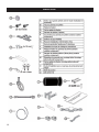
16
Matériel fourni
4x15mm
4x16mm
4x16mm

17
Exigences d’encastrement
AVERTISSEMENT
Évitez les brûlures ou les risques de secousse électrique !
S’assurer que l’alimentation d’eau et l’alimentation électrique
sont mises à l’arrêt avant toute installation ou réparation.
REMARQUE : ce lave-vaisselle est conçu pour être en-
castré sous un comptoir et entre deux armoires adjacen-
tes standard d’une cuisine résidentielle.
Choisir un emplacement aussi près que possible de
l’évier afin que les tuyaux d’alimentation et
d’évacuation d’eau soient facilement accessibles.
Pour un fonctionnement adéquat du lave-vaisselle
et un aspect esthétique agréable, vérifier que
l’encadrement est d’équerre et qu’il a les dimen-
sions indiquées sur la Figure 1 ci-dessous.
Figure 1
REMARQUE : si la largeur de l’ouverture de votre lave-
vaisselle est supérieure à >23
5/8
Ǝ po (600 mm) utilisez les
méthodes de MONTAGE PAR LE DESSUS ou LATÉ-
RAL. ISi la largeur de l’ouverture de votre lave-vaisselle
est inférieure à 23
5/8
Ǝ po (600 mm) utilisez la méthode de
MONTAGE LATÉRAL ALTERNATIF.
Si le lave-vaisselle doit être installé dans un coin de
la pièce, s’assurer qu’il y a un dégagement suffisant
pour ouvrir la porte. Voir la Figure 2 ci-dessous.
Figure 2
AVERTISSEMENT
É
vitez les risques de décharge électrique et d’incendie.
Les câbles électriques et les tuyaux d’alimentation d’eau
ne doivent pas entrer en contact les uns avec les autres.
Après avoir trouvé l’emplacement adéquat pour installer
votre nouveau lave-vaisselle, vous devez prévoir les
ouvertures nécessaires pour permettre le passage des
conduites d’eau, d’évacuation et d’électricité. Pour éviter
toute interférence lors de l’installation du lave-vaisselle
dans l’armoire, disposer les ouvertures compte tenu des
dimensions indiquées sur la Figure 3 ci-dessous.
Figure 3
Ouvertures requises :
4
3/4
Ǝ x 2
3/8
Ǝ (120 x 60 mm) - Passage du boîtier de rac-
cordement électrique compris à travers une armoire ad-
jacente.
REMARQUE : si les raccordements d’arrivée
d’électricité, d’alimentation d’eau et de vidange se trou-
vent tous dans la même armoire, une ouverture de 4
3/4
Ǝ x
2
3/8
Ǝ (120 x 60 mm) est suffisante pour recevoir les trois.
4Ǝ x 2Ǝ (100 x 50 mm) - Passage du tuyau d’alimentation
d’eau compris vers l’alimentation d’eau
1
1/4
Ǝ (32 mm) diameter - Passage du tuyau de vidange
du lave-vaisselle vers le raccordement de vidange.
Avant d’encastrer le lave-vaisselle dans l’armoire, retirer
le collier de serrage à l’arrière du lave-vaisselle comme
indiqué (Figure 4). Le collier de serrage peut être utilisé
ultérieurement pour maintenir le tuyau de vidange en
place (Figure 10).
Figure 4
Sur certains modèles, il convient d’enlever le tablier de
caoutchouc sur la partie supérieure du lave-vaisselle et
de le mettre en réserve pour un usage ultérieur. Figure 5.
Figure 5

18
Préparation de l’installation électrique
AVERTISSEMENT
Évitez les risques de décharge électrique et d’incendie.
Ne pas tenter d’intervenir sur un circuit sous tension.
Vous risquez autrement des blessures graves, voire la
mort. Seuls les électriciens qualifiés doivent effectuer
des travaux sur l’installation électrique. Ne pas tenter
d’intervenir sur le circuit électrique du lave-vaisselle à
moins d’être certain que celui-ci est hors tension.
AVERTISSEMENT
Éviter les risques d’incendie
Vérifier que l’installation électrique est correctement ré-
alisée. Seuls les électriciens qualifiés doivent effectuer
des travaux sur l’installation électrique.
Alimentation électrique
Le client a la responsabilité de vérifier que l’installation
électrique du lave-vaisselle est conforme à tous les
codes et ordonnances électriques nationaux et locaux.
Le lave-vaisselle a été conçu pour fonctionner avec
une alimentation électrique en courant alternatif de
120 volts, 60 Hz, connectée à un circuit électrique
correctement mis à la terre, conçu pour les lave-
vaisselle, avec protection par fusible ou disjoncteur
d’une puissance de 15 ampères. Les conducteurs
d’alimentation électrique doivent être en fl de cuivre
de calibre 14 AWG minimum à une température no-
minale de 75°C (167°F) ou plus.
AVERTISSEMENT
Éviter les risques d’incendie
S’assurer que les branchements électriques sont bien
serrés. S’assurer que tous les branchements électriques
sont bien faits.
Instructions de mise à la terre
Le lave-vaisselle doit être correctement mis à la terre
avant toute utilisation. Cet appareil doit être raccordé
à un système de câblage en métal permanent mis à la
terre ou un conducteur de mise à la terre du matériel
doit être utilisé avec les conducteurs du circuit et rac-
cordé à la borne de mise à la terre de l’appareil ou au
fil conducteur du lave-vaisselle. S’assurer que le lave-
vaisselle est relié à une masse adéquate conformé-
ment à tous les codes locaux, et en l’absence de code
local, au CODE NATIONAL D’ÉLECTRICITÉ aux
États-Unis ou au CODE D’ÉLECTRICITÉ DU CANA-
DA, C22.1, dernière édition au Canada, ainsi qu’aux
codes provinciaux, d’état ou municipaux qui
s’appliquent.
Caractéristiques électriques du lave-vaisselle
Volts Hertz Amperes Watts
120 60 12 1,300 (max)
La boîte de jonction de l’alimentation électrique du
lave-vaisselle et la prise dédiée doivent être installées
dans une armoire accessible adjacente au lave-
vaisselle (ne pas monter la boîte de jonction ni la prise
derrière l’appareil). Vous aurez besoin d’une ouverture
de 4
3/4
Ǝ x 2
3/8
Ǝ (120 x 60 mm) pratiquée dans l’armoire
pour pouvoir y passer la boîte de jonction (Figure 6).
Si l’ouverture est percée dans du bois, poncer le pour-
tour de l’orifice. Si l’ouverture est percée dans du mé-
tal, utiliser la gaine protectrice comprise ou toute autre
méthode approuvée pour protéger le câblage de tout
dommage. Utiliser les quatre vis comprises (ou le dis-
positif de fixation approprié) se trouvant dans le sa-
chet contenant les pièces pour fixer la boîte de jonc-
tion en toute sécurité afin qu’elle soit facilement ac-
cessible (voir la Figure 6). L’alimentation électrique
peut être branchée de deux façons :
Figure 6
Méthode A - Fiche à trois broches et prise
Utiliser la fiche à trois broches et la boîte de jonction
comprises pour brancher l’alimentation sur une prise
résidentielle dédiée. S’assurer que la prise résidentielle
répond aux spécifications relatives à l’alimentation élec-
trique ainsi qu’aux codes nationaux ou locaux.
Figure 7
La page charge ...
La page charge ...
La page charge ...
La page charge ...
La page charge ...
La page charge ...
La page charge ...
La page charge ...
-
 1
1
-
 2
2
-
 3
3
-
 4
4
-
 5
5
-
 6
6
-
 7
7
-
 8
8
-
 9
9
-
 10
10
-
 11
11
-
 12
12
-
 13
13
-
 14
14
-
 15
15
-
 16
16
-
 17
17
-
 18
18
-
 19
19
-
 20
20
-
 21
21
-
 22
22
-
 23
23
-
 24
24
-
 25
25
-
 26
26
-
 27
27
-
 28
28


