Lincoln Electric Red-D-Arc LN-25 Pro Extreme Mode d'emploi
- Catégorie
- Système de soudage
- Taper
- Mode d'emploi

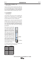
RED-D-ARC
LN25™ PRO EXTREME DUAL POWER
IM10080-A
August 2013
Red-D-Arc Spec-Built Welding Equipment
This
RED-D-ARC
welder is built to
RED-D-ARC Extreme Duty
design specifications by Lincoln Electric.
Safety Depends on You
This welder is designed and built with safety in mind.
However, your overall safety can be increased by proper installation
... and thoughtful operation on your part.
DO NOT INSTALL, OPERATE OR REPAIR THIS EQUIPMENT
WITHOUT READING THIS MANUAL AND THE SAFETY
PRECAUTIONS CONTAINED THROUGHOUT.
And, most importantly, think before you act and be careful.
For use with machines having Code Numbers: 11750, 12164
North America’s Largest Fleet of Welding Equipment
1-800-245-3660
OPERATOR’S MANUAL

THANK YOU FOR SELECTING
A QUALITY PRODUCT BY
LINCOLN ELEC TRIC.
PLEASE EXAMINE CARTON AND EQUIPMENT FOR
DAMAGE IMMEDIATELY
When this equipment is shipped, title passes to the purchaser
upon receipt by the carrier. Consequently, claims for material
damaged in shipment must be made by the purchaser against the
transportation company at the time the shipment is received.
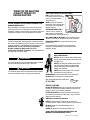
SAFETY DEPENDS ON YOU
Lincoln arc welding and cutting equipment is designed and built
with safety in mind. However, your overall safety can be increased
by proper installation ... and thoughtful operation on your part.
DO NOT INSTALL, OPERATE OR REPAIR THIS EQUIPMENT
WITHOUT READING THIS MANUAL AND THE SAFETY
PRECAUTIONS CONTAINED THROUGHOUT. And, most importantly,
think before you act and be careful.
This statement appears where the information must be followed
exactly to avoid serious personal injury or loss of life.
This statement appears where the information must be followed
to avoid minor personal injury or damage to this equipment.
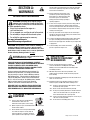
KEEP YOUR HEAD OUT OF THE FUMES.
DON’T get too close to the arc.
Use corrective lenses if necessary
to stay a reasonable distance
away from the arc.
READ and obey the Safety Data
Sheet (SDS) and the warning label
that appears on all containers of
welding materials.
USE ENOUGH VENTILATION or
exhaust at the arc, or both, to
keep the fumes and gases from
your breathing zone and the general area.
IN A LARGE ROOM OR OUTDOORS, natural ventilation may be
adequate if you keep your head out of the fumes (See below).
USE NATURAL DRAFTS or fans to keep the fumes away
from your face.
If you de velop unusual symptoms, see your supervisor.
Perhaps the welding atmosphere and ventilation system
should be checked.
WEAR CORRECT EYE, EAR &
BODY PROTECTION
PROTECT your eyes and face with welding helmet
properly fitted and with proper grade of filter plate
(See ANSI Z49.1).
PROTECT your body from welding spatter and arc
flash with protective clothing including woolen
clothing, flame-proof apron and gloves, leather
leggings, and high boots.
PROTECT others from splatter, flash, and glare
with protective screens or barriers.
IN SOME AREAS, protection from noise may be appropriate.
BE SURE protective equipment is in good condition.
Also, wear safety glasses in work area
AT ALL TIMES.
SPECIAL SITUATIONS
DO NOT WELD OR CUT containers or materials which previously
had been in contact with hazardous substances unless they are
properly cleaned. This is extremely dangerous.
DO NOT WELD OR CUT painted or plated parts unless special
precautions with ventilation have been taken. They can release
highly toxic fumes or gases.
Additional precautionary measures
PROTECT compressed gas cylinders from excessive heat,
mechanical shocks, and arcs; fasten cylinders so they cannot fall.
BE SURE cylinders are never grounded or part of an
electrical circuit.
REMOVE all potential fire hazards from welding area.
ALWAYS HAVE FIRE FIGHTING EQUIPMENT READY FOR
IMMEDIATE USE AND KNOW HOW TO USE IT.
WARNING
CAUTION
Safety 01 of 04 - 5/16/2018

SECTION A:
WARNINGS
CALIFORNIA PROPOSITION 65 WARNINGS
WARNING: Breathing diesel engine exhaust
exposes you to chemicals known to the State
of California to cause cancer and birth defects,
or other reproductive harm.
• Always start and operate the engine in a
well-ventilated area.
• If in an exposed area, vent the exhaust to the outside.
• Do not modify or tamper with the exhaust system.
• Do not idle the engine except as necessary.
For more information go to
www.P65 warnings.ca.gov/diesel
WARNING: This product, when used for welding or
cutting, produces fumes or gases which contain
chemicals known to the State of California to cause
birth defects and, in some cases, cancer. (California
Health & Safety Code § 25249.5 et seq.)
WARNING: Cancer and Reproductive Harm
www.P65warnings.ca.gov
ARC WELDING CAN BE HAZARDOUS. PROTECT
YOURSELF AND OTHERS FROM POSSIBLE SERIOUS
INJURY OR DEATH. KEEP CHILDREN AWAY.
PACEMAKER WEARERS SHOULD CONSULT WITH
THEIR DOCTOR BEFORE OPERATING.
Read and understand the following safety highlights. For
additional safety information, it is strongly recommended
that you purchase a copy of “Safety in Welding & Cutting -
ANSI Standard Z49.1” from the American Welding Society,
P.O. Box 351040, Miami, Florida 33135 or CSA Standard
W117.2-1974. A Free copy of “Arc Welding Safety” booklet
E205 is available from the Lincoln Electric Company,
22801 St. Clair Avenue, Cleveland, Ohio 44117-1199.
BE SURE THAT ALL INSTALLATION, OPERATION,
MAINTENANCE AND REPAIR PROCEDURES ARE
PERFORMED ONLY BY QUALIFIED INDIVIDUALS.
FOR ENGINE POWERED
EQUIPMENT.
1.a. Turn the engine off before troubleshooting
and maintenance work unless the
maintenance work requires it to be running.
1.b. Operate engines in open, well-ventilated areas or vent the engine
exhaust fumes outdoors.
1.c. Do not add the fuel near an open flame welding
arc or when the engine is running. Stop the
engine and allow it to cool before refueling to
prevent spilled fuel from vaporizing on contact
with hot engine parts and igniting. Do not spill fuel when filling
tank. If fuel is spilled, wipe it up and do not start engine until
fumes have been eliminated.
1.d. Keep all equipment safety guards, covers
and devices in position and in good repair.
Keep hands, hair, clothing and tools away
from V-belts, gears, fans and all other
moving parts when starting, operating or
repairing equipment.
1.e. In some cases it may be necessary to remove safety guards to
perform required maintenance. Remove guards only when
necessary and replace them when the maintenance requiring
their removal is complete. Always use the greatest care when
working near moving parts.
1.f. Do not put your hands near the engine fan. Do not attempt to
override the governor or idler by pushing on the throttle control
rods while the engine is running.
1.g. To prevent accidentally starting gasoline engines while turning
the engine or welding generator during maintenance work,
disconnect the spark plug wires, distributor cap or magneto wire
as appropriate.
1.h. To avoid scalding, do not remove the radiator
pressure cap when the engine is
hot.
ELECTRIC AND
MAGNETIC FIELDS MAY
BE DANGEROUS
2.a. Electric current flowing through any conductor
causes localized Electric and Magnetic Fields (EMF).
Welding current creates EMF fields around welding cables
and welding machines
2.b. EMF fields may interfere with some pacemakers, and
welders having a pacemaker should consult their physician
before welding.
2.c. Exposure to EMF fields in welding may have other health effects
which are now not known.
2.d. All welders should use the following procedures in order to
minimize exposure to EMF fields from the welding circuit:
2.d.1. Route the electrode and work cables together - Secure
them with tape when possible.
2.d.2. Never coil the electrode lead around your body.
2.d.3. Do not place your body between the electrode and work
cables. If the electrode cable is on your right side, the
work cable should also be on your right side.
2.d.4. Connect the work cable to the workpiece as close as pos-
sible to the area being welded.
2.d.5. Do not work next to welding power source.
SAFETY
Safety 02 of 04 - 5/16/2018

ELECTRIC SHOCK
CAN KILL.
3.a. The electrode and work (or ground) circuits are
electrically “hot” when the welder is on. Do
not touch these “hot” parts with your bare skin or wet clothing.
Wear dry, hole-free gloves to insulate hands.
3.b. Insulate yourself from work and ground using dry insulation.
Make certain the insulation is large enough to cover your full area
of physical contact with work and ground.
In addition to the normal safety precautions, if
welding must be performed under electrically
hazardous conditions (in damp locations or while
wearing wet clothing; on metal structures such as
floors, gratings or scaffolds; when in cramped
positions such as sitting, kneeling or lying, if there
is a high risk of unavoidable or accidental contact
with the workpiece or ground) use the following
equipment:
• Semiautomatic DC Constant Voltage (Wire) Welder.
• DC Manual (Stick) Welder.
• AC Welder with Reduced Voltage Control.
3.c. In semiautomatic or automatic wire welding, the electrode,
electrode reel, welding head, nozzle or semiautomatic welding
gun are also electrically “hot”.
3.d. Always be sure the work cable makes a good electrical
connection with the metal being welded. The connection should
be as close as possible to the area being welded.
3.e. Ground the work or metal to be welded to a good electrical (earth)
ground.
3.f. Maintain the electrode holder, work clamp, welding cable and
welding machine in good, safe operating condition. Replace
damaged insulation.
3.g. Never dip the electrode in water for cooling.
3.h. Never simultaneously touch electrically “hot” parts of electrode
holders connected to two welders because voltage
between the
two can be the total of the open circuit voltage of both
welders.
3.i. When working above floor level, use a safety belt to protect
yourself from a fall should you get a shock.
3.j. Also see It ems 6.c. and 8.
ARC RAYS CAN BURN.
4.a. Use a shield with the proper filter and cover plates to protect your
eyes from sparks and the rays of the arc when welding or
observing open arc welding. Headshield and filter lens should
conform to ANSI Z87. I standards.
4.b. Use suitable clothing made from durable flame-resistant material
to protect your skin and that of your helpers from the arc rays.
4.c. Protect other nearby personnel with suitable, non-flammable
screening and/or warn them not to watch the arc nor expose
themselves to the arc rays or to hot spatter or metal.
FUMES AND GASES
CAN BE DANGEROUS.
5.a. Welding may produce fumes and gases
hazardous to health. Avoid breathing these
fumes and gases. When welding, keep your head out of the fume.
Use enough ventilation and/or exhaust at the arc to keep fumes
and gases away from the breathing zone. When welding
hardfacing (see instructions on container or SDS)
or on lead or cadmium plated steel and other
metals or coatings which produce highly toxic
fumes, keep exposure as low as possible and
within applicable OSHA PEL and ACGIH TLV limits
using local exhaust or mechanical ventilation
unless exposure assessments indicate otherwise.
In confined spaces or in some circumstances,
outdoors, a respirator may also be required.
Additional precautions are also required when
welding
on galvanized steel.
5. b. The operation of welding fume control equipment is affected by
various factors including proper use and positioning of the
equipment, maintenance of the equipment and the specific
welding procedure and application involved. Worker exposure
level should be checked upon installation and periodically
thereafter to be certain it is within applicable OSHA PEL and
ACGIH TLV limits.
5.c. Do not weld in locations near chlorinated hydrocarbon vapors
coming from degreasing, cleaning or spraying operations. The
heat and rays of the arc can react with solvent vapors to form
phosgene, a highly toxic gas, and other irritating products.
5.d. Shielding gases used for arc welding can displace air and
cause
injury or death. Always use enough ventilation, especially in
confined areas, to insure breathing air is safe.
5.e. Read and understand the manufacturer’s instructions for this
equipment and the consumables to be used, including the
Safety Data Sheet (SDS) and follow your employer’s safety
practices. SDS forms are available from your welding
distributor or from the manufacturer.
5.f. Also see item 1.b.
SAFETY
Safety 03 of 04 - 5/16/2018

WELDING AND CUTTING
SPARKS CAN CAUSE
FIRE OR EXPLOSION.
6.a. Remove fire hazards from the welding area. If
this is not possible, cover them to prevent the welding sparks
from starting a fire. Remember that welding sparks and hot
materials from welding can easily go through small cracks and
openings to adjacent areas. Avoid welding near hydraulic lines.
Have a fire extinguisher readily available.
6.b. Where compressed gases are to be used at the job site, special
precautions should be used to prevent hazardous situations.
Refer to “Safety in Welding and Cutting” (ANSI Standard Z49.1)
and the operating information for the equipment being used.
6.c. When not welding, make certain no part of the electrode circuit is
touching the work or ground. Accidental contact can cause
overheating and create a fire hazard.
6.d. Do not heat, cut or weld tanks, drums or containers until the
proper steps have been taken to insure that such procedures
will not cause flammable or toxic vapors from substances inside.
They can cause an explosion even though they have been
“cleaned”. For information, purchase “Recommended Safe
Practices for the Preparation for Welding and Cutting of
Containers and Piping That Have Held Hazardous Substances”,
AWS F4.1 from the American Welding Society
(see address above).
6.e. Vent hollow castings or containers before heating, cutting or
welding. They may explode.
6.f. Sparks and spatter are thrown from the welding arc. Wear oil free
protective garments such as leather gloves, heavy shirt, cuffless
trousers, high shoes and a cap over your hair. Wear ear plugs
when welding out of position or in confined places. Always wear
safety glasses with side shields when in a welding area.
6.g. Connect the work cable to the work as close to the welding area
as practical. Work cables connected to the building framework or
other locations away from the welding area increase the
possibility of the welding current passing through lifting chains,
crane cables or other alternate circuits. This can create fire
hazards or overheat lifting chains or cables until they fail.
6.h. Also see item 1.c.
6.I. Read and follow NFPA 51B “Standard for Fire Prevention During
Welding, Cutting and Other Hot Work”, available from NFPA, 1
Batterymarch Park, PO box 9101, Quincy, MA 022690-9101.
6.j. Do not use a welding power source for pipe thawing.
CYLINDER MAY EXPLODE IF
DAMAGED.
7.a. Use only compressed gas cylinders containing
the correct shielding gas for the process used
and properly operating regulators designed for
the gas and pressure used. All hoses, fittings,
etc. should be suitable for the application and
maintained in good condition.
7.b. Always keep cylinders in an upright position securely chained to
an undercarriage or fixed support.
7.c. Cylinders should be located:
• Away from areas where they may be struck or subjected
to physical damage.
• A safe distance from arc welding or cutting operations
and any other source of heat, sparks, or flame.
7.d. Never allow the electrode, electrode holder or any other
electrically “hot” parts to touch a cylinder.
7.e. Keep your head and face away from the cylinder valve outlet
when opening the cylinder valve.
7.f. Valve protection caps should always be in place and hand tight
except when the cylinder is in use or connected for use.
7.g. Read and follow the instructions on compressed gas cylinders,
associated equipment, and CGA publication P-l, “Precautions for
Safe Handling of Compressed Gases in Cylinders,” available from
the Compressed Gas Association, 14501 George Carter Way
Chantilly, VA 20151.
FOR ELECTRICALLY
POWERED EQUIPMENT.
8.a. Turn off input power using the disconnect
switch at the fuse box before working on
the equipment.
8.b. Install equipment in accordance with the U.S. National Electrical
Code, all local codes and the manufacturer’s recommendations.
8.c. Ground the equipment in accordance with the U.S. National
Electrical Code and the manufacturer’s recommendations.
Refer to
http://www.lincolnelectric.com/safety
for additional safety information.
SAFETY
Safety 04 of 04 - 5/16/2018

iv
SAFETY
iv
PRÉCAUTIONS DE SÛRETÉ
Pour votre propre protection lire et observer toutes les instructions
et les précautions de sûreté specifiques qui parraissent dans ce
manuel aussi bien que les précautions de sûreté générales suiv-
antes:
Sûreté Pour Soudage A LʼArc
1. Protegez-vous contre la secousse électrique:
a. Les circuits à lʼélectrode et à la piéce sont sous tension
quand la machine à souder est en marche. Eviter toujours
tout contact entre les parties sous tension et la peau nue
ou les vétements mouillés. Porter des gants secs et sans
trous pour isoler les mains.
b. Faire trés attention de bien sʼisoler de la masse quand on
soude dans des endroits humides, ou sur un plancher
metallique ou des grilles metalliques, principalement dans
les positions assis ou couché pour lesquelles une grande
partie du corps peut être en contact avec la masse.
c. Maintenir le porte-électrode, la pince de masse, le câble
de soudage et la machine à souder en bon et sûr état
defonctionnement.
d.Ne jamais plonger le porte-électrode dans lʼeau pour le
refroidir.
e. Ne jamais toucher simultanément les parties sous tension
des porte-électrodes connectés à deux machines à souder
parce que la tension entre les deux pinces peut être le
total de la tension à vide des deux machines.
f. Si on utilise la machine à souder comme une source de
courant pour soudage semi-automatique, ces precautions
pour le porte-électrode sʼapplicuent aussi au pistolet de
soudage.
2. Dans le cas de travail au dessus du niveau du sol, se protéger
contre les chutes dans le cas ou on recoit un choc. Ne jamais
enrouler le câble-électrode autour de nʼimporte quelle partie
du corps.
3. Un coup dʼarc peut être plus sévère quʼun coup de soliel,
donc:
a. Utiliser un bon masque avec un verre filtrant approprié
ainsi quʼun verre blanc afin de se protéger les yeux du ray-
onnement de lʼarc et des projections quand on soude ou
quand on regarde lʼarc.
b. Porter des vêtements convenables afin de protéger la
peau de soudeur et des aides contre le rayonnement de
lʻarc.
c. Protéger lʼautre personnel travaillant à proximité au
soudage à lʼaide dʼécrans appropriés et non-inflammables.
4. Des gouttes de laitier en fusion sont émises de lʼarc de
soudage. Se protéger avec des vêtements de protection libres
de lʼhuile, tels que les gants en cuir, chemise épaisse, pan-
talons sans revers, et chaussures montantes.
5. Toujours porter des lunettes de sécurité dans la zone de
soudage. Utiliser des lunettes avec écrans lateraux dans les
zones où lʼon pique le laitier.
6. Eloigner les matériaux inflammables ou les recouvrir afin de
prévenir tout risque dʼincendie dû aux étincelles.
7. Quand on ne soude pas, poser la pince à une endroit isolé de
la masse. Un court-circuit accidental peut provoquer un
échauffement et un risque dʼincendie.
8. Sʼassurer que la masse est connectée le plus prés possible
de la zone de travail quʼil est pratique de le faire. Si on place
la masse sur la charpente de la construction ou dʼautres
endroits éloignés de la zone de travail, on augmente le risque
de voir passer le courant de soudage par les chaines de lev-
age, câbles de grue, ou autres circuits. Cela peut provoquer
des risques dʼincendie ou dʼechauffement des chaines et des
câbles jusquʼà ce quʼils se rompent.
9. Assurer une ventilation suffisante dans la zone de soudage.
Ceci est particuliérement important pour le soudage de tôles
galvanisées plombées, ou cadmiées ou tout autre métal qui
produit des fumeés toxiques.
10. Ne pas souder en présence de vapeurs de chlore provenant
dʼopérations de dégraissage, nettoyage ou pistolage. La
chaleur ou les rayons de lʼarc peuvent réagir avec les vapeurs
du solvant pour produire du phosgéne (gas fortement toxique)
ou autres produits irritants.
11. Pour obtenir de plus amples renseignements sur la sûreté,
voir le code “Code for safety in welding and cutting” CSA
Standard W 117.2-1974.
PRÉCAUTIONS DE SÛRETÉ POUR
LES MACHINES À SOUDER À
TRANSFORMATEUR ET À
REDRESSEUR
1. Relier à la terre le chassis du poste conformement au code de
lʼélectricité et aux recommendations du fabricant. Le dispositif
de montage ou la piece à souder doit être branché à une
bonne mise à la terre.
2. Autant que possible, Iʼinstallation et lʼentretien du poste seront
effectués par un électricien qualifié.
3. Avant de faires des travaux à lʼinterieur de poste, la debranch-
er à lʼinterrupteur à la boite de fusibles.
4. Garder tous les couvercles et dispositifs de sûreté à leur
place.

vv
SAFETY
Electromagnetic Compatibility (EMC)
Conformance
Products displaying the CE mark are in conformity with European Community Council Directive of 15 Dec
2004 on the approximation of the laws of the Member States relating to electromagnetic compatibility,
2004/108/EC. It was manufactured in conformity with a national standard that implements a harmonized
standard: EN 60974-10 Electromagnetic Compatibility (EMC) Product Standard for Arc Welding Equipment.
It is for use with other Lincoln Electric equipment. It is designed for industrial and professional use.
Introduction
All electrical equipment generates small amounts of electromagnetic emission. Electrical emission may be
transmitted through power lines or radiated through space, similar to a radio transmitter. When emissions
are received by other equipment, electrical interference may result. Electrical emissions may affect many
kinds of electrical equipment; other nearby welding equipment, radio and TV reception, numerical controlled
machines, telephone systems, computers, etc. Be aware that interference may result and extra precautions
may be required when a welding power source is used in a domestic establishment.
Installation and Use
The user is responsible for installing and using the welding equipment according to the manufacturer’s
instructions. If electromagnetic disturbances are detected then it shall be the responsibility of the user of the
welding equipment to resolve the situation with the technical assistance of the manufacturer. In some cases
this remedial action may be as simple as earthing (grounding) the welding circuit, see Note. In other cases it
could involve construction of an electromagnetic screen enclosing the power source and the work complete
with associated input filters. In all cases electromagnetic disturbances must be reduced to the point where
they are no longer troublesome.
Note: The welding circuit may or may not be earthed for safety reasons according to national codes.
Changing the earthing arrangements should only be authorized by a person who is compe-
tent to access whether the changes will increase the risk of injury, e.g., by allowing parallel
welding current return paths which may damage the earth circuits of other equipment.
Assessment of Area
Before installing welding equipment the user shall make an assessment of potential electromagnetic prob-
lems in the surrounding area. The following shall be taken into account:
a) other supply cables, control cables, signaling and telephone cables; above, below and adjacent to the
welding equipment;
b) radio and television transmitters and receivers;
c) computer and other control equipment;
d) safety critical equipment, e.g., guarding of industrial equipment;
e) the health of the people around, e.g., the use of pacemakers and hearing aids;
f) equipment used for calibration or measurement
g) the immunity of other equipment in the environment. The user shall ensure that other equipment being
used in the environment is compatible. This may require additional protection measures;
h) the time of day that welding or other activities are to be carried out.

vivi
SAFETY
Electromagnetic Compatibility (EMC)
The size of the surrounding area to be considered will depend on the structure of the building and other
activities that are taking place. The surrounding area may extend beyond the boundaries of the premises.
Methods of Reducing Emissions
Mains Supply
Welding equipment should be connected to the mains supply according to the manufacturer’s recommenda-
tions. If interference occurs, it may be necessary to take additional precautions such as filtering of the mains
supply. Consideration should be given to shielding the supply cable of permanently installed welding equip-
ment, in metallic conduit or equivalent. Shielding should be electrically continuous throughout its length. The
shielding should be connected to the welding power source so that good electrical contact is maintained
between the conduit and the welding power source enclosure.
Maintenance of the Welding Equipment
The welding equipment should be routinely maintained according to the manufacturer’s recommendations.
All access and service doors and covers should be closed and properly fastened when the welding equip-
ment is in operation. The welding equipment should not be modified in any way except for those changes
and adjustments covered in the manufacturers instructions. In particular, the spark gaps of arc striking and
stabilizing devices should be adjusted and maintained according to the manufacturer’s recommendations.
Welding Cables
The welding cables should be kept as short as possible and should be positioned close together, running at
or close to floor level.
Equipotential Bonding
Bonding of all metallic components in the welding installation and adjacent to it should be considered.
However, metallic components bonded to the work piece will increase the risk that the operator could
receive a shock by touching these metallic components and the electrode at the same time. The operator
should be insulated from all such bonded metallic components.
Earthing of the Workpiece
Where the workpiece is not bonded to earth for electrical safety, not connected to earth because of its size
and position, e.g., ships hull or building steelwork, a connection bonding the workpiece to earth may reduce
emissions in some, but not all instances. Care should be taken to prevent the earthing of the workpiece
increasing the risk of injury to users, or damage to other electrical equipment. Where necessary, the connec-
tion of the workpiece to earth should be made by a direct connection to the workpiece, but in some countries
where direct connection is not permitted, the bonding should be achieved by suitable capacitance, selected
according to national regulations.
Screening and Shielding
Selective screening and shielding of other cables and equipment in the surrounding area may alleviate prob-
lems of interference. Screening of the entire welding installation may be considered for special
applications
1.
_________________________
1
Portions of the preceding text are contained in EN 60974-10: “Electromagnetic Compatibility (EMC) prod-
uct standard for arc welding equipment.”

viii
viii
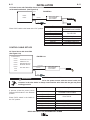
TABLE OF CONTENTS
Page
––––––––––––––––––––––––––––––––––––––––––––––––––––––––––––––––––––––––––––––––
Installation.......................................................................................................................Section A
Technical Specifications.......................................................................................................A-1
Safety Precautions ...............................................................................................................A-2
Location................................................................................................................................A-2
High Frequency Protection...................................................................................................A-2
Weld cable Sizes..................................................................................................................A-2
Analog Control Cable ...........................................................................................................A-3
Cable Connections and Control Cable Connector ...............................................................A-4
Shielding Gas Connection....................................................................................................A-4
Wire Drive Configuration ......................................................................................................A-5
Gun Receiver Bushing, Thumb Screw and Socket Head Cap Screw ..........................A-5, A-6
Procedure to Install Drive Rolls and Wire Guides ..............................................................A-7
Pressure Arm Adjustment ....................................................................................................A-8
Loading Spools of Wire ........................................................................................................A-8
Gun Connections..................................................................................................................A-8
Power Source to RED-D-ARC LN25™ PRO EXTREME DUAL POWER Cable Connection
Diagrams ..............................................................................................................A-9 thru A-11
________________________________________________________________________________
Operation.........................................................................................................................Section B
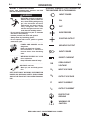
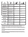
Safety Precautions ...............................................................................................................B-1
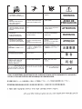
Graphic Symbols that appear on this Machine or in this Manual .........................................B-1
Definition of Welding Terms .................................................................................................B-2
General Description..............................................................................................................B-2
Recommended Processes, Process & Equipment Limitations, Recommended Power Sources
........B-2
Wire Feed Speed CV and CC, Arc Volts..............................................................................B-3
Constant Current Wire Welding............................................................................................B-4
Case Front Controls .............................................................................................B-5, thru B-8
Internal Controls .........................................................................................................B-9, B-10
Rear Controls .....................................................................................................................B-11
Gas Purge Pushbutton, Flow Meter ...................................................................................B-12
________________________________________________________________________________
Accessories ....................................................................................................................Section C
Factory Installed Equipment.................................................................................................C-1
Drive Roll Kits used..............................................................................................................C-1
Accessories Used ..................................................................................................C-1 thru C-4
________________________________________________________________________________
Maintenance....................................................................................................................Section D
Safety Precautions ...............................................................................................................D-1
Routine Maintenance ...........................................................................................................D-1
Periodic Maintenance...........................................................................................................D-1
Calibration Specification.......................................................................................................D-1
________________________________________________________________________________
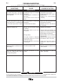
Troubleshooting .............................................................................................................Section E
How to Use Troubleshooting Guide .....................................................................................E-1
Digital Display Models Error Codes......................................................................................E-2
Troubleshooting Guide .................................................................................................E-3, E-4
________________________________________________________________________________
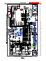
Wiring Diagram & Dimension Prints .............................................................................Section F
________________________________________________________________________________
Parts Pages ................................................................................................................P-670 Series
_______________________________________________________________________
________

A-1
INSTALLATION
A-1
RED-D-ARC LN25™ PRO EXTREME DUAL POWER
TEMPERATURE RANGE
OPERATION: -40°F to 104°F (-40°C to 40°C)
STORAGE: -40°F to 122°F (-40°C to 50°C)
INPUT VOLTAGE and CURRENT
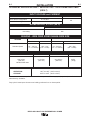
TECHNICAL SPECIFICATIONS –
RED-D-ARC LN25™ PRO EXTREME DUAL POWER
(K2614-7)
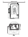
HEIGHT WIDTH DEPTH WEIGHT
14.8 Inches 8.7 Inches 23.2 Inches 40 lbs
(376 mm) ( 221 mm) (589 mm) (18 kg)
Handle folded down
PHYSICAL DIMENSIONS
INPUT VOLTAGE ± 10%
Across the Arc configuration 15-110 VDC
Control Cable configuration 24-42 VAC
INPUT AMPERES
4A
RATED OUTPUT @ 104°F (40°C)
DUTY CYCLE
60% rating
INPUT AMPERES
450
GEARING - WIRE FEED SPEED RANGE-WIRE SIZE
WFS RANGE
50 – 700 ipm
(1.3 – 17.7m/min)
WFS RANGE
50 – 700 ipm
(1.3 – 17.7m/min)
WIRE SIZES
.023 – 1/16"
(0.6 – 1.6mm)
WIRE SIZES
.030 - 5/64
(0.8 - 2.0mm)
GEARING
Standard Speed
Thermal tests have been performed at ambient temperature. The duty cycle (duty factor) at 40°C has been
determined by simulation.
Duty cycle is based upon the amount of welding performed in a 10 minute period.
GMAW
FCAW

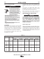
WELD CABLE SIZE
Table A.1 located below are copper cable sizes rec-
ommended for different currents and duty cycles.
Lengths stipulated are the distance from the welder to
work and back to the welder again. Cable sizes are
increased for greater lengths primarily for the purpose
of minimizing cable drop.
** Tabled values are for operation at ambient temperatures of 104°F(40°C) and below. Applications above 104°F(40°C) may require cables
larger than recommended, or cables rated higher than 167°F(75°C).
RECOMMENDED CABLE SIZES (RUBBER COVERED COPPER - RATED 167°F or 75°C)**
CABLE SIZES FOR COMBINED LENGTHS OF ELECTRODE AND WORK CABLES
AMPERES
200
200
225
225
250
250
250
250
300
325
350
400
400
500
PERCENT
DUTY
CYCLE
60
100
20
40 & 30
30
40
60
100
60
100
60
60
100
60
0 to 50Ft.
(0 to15m)
2
2
4 or 5
3
3
2
1
1
1
2/0
1/0
2/0
3/0
2/0
50 to 100Ft.
(15 to 30m)
2
2
3
3
3
2
1
1
1
2/0
1/0
2/0
3/0
2/0
100 to 150 Ft.
(30 to 46m)
2
2
2
2
2
1
1
1
1
2/0
2/0
2/0
3/0
3/0
150 to 200 Ft.
(46 to 61m)
1
1
1
1
1
1
1
1
1/0
2/0
2/0
3/0
3/0
3/0
200 to 250 Ft.
(61 to 76m)
1/0
1/0
1/0
1/0
1/0
1/0
1/0
1/0
2/0
3/0
3/0
4/0
4/0
4/0
TABLE A.1
A-2
INSTALLATION
RED-D-ARC LN25™ PRO EXTREME DUAL POWER
A-2
SAFETY PRECAUTIONS
ELECTRIC SHOCK CAN KILL.
• Turn the input power OFF at the
disconnect switch or fuse box
before attempting to connect or
disconnect input power lines, out-
put cables or control cables.
• Only qualified personnel should
perform this installation.
• Do not touch metal portions of the work clip
when the welding power source is on.
• Do not attach the work clip to the wire feeder.
• Connect the work clip directly to the work, as
close as possible to the welding arc.
• Turn power off at the welding power source
before disconnecting the work clip from the
work.
• Only use on power sources with open circuit
voltages less than 110 VDC.
------------------------------------------------------------------------
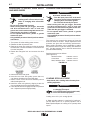
LOCATION
For best wire feeding performance, place the RED-
D-ARC LN25™ PRO EXTREME DUAL POWER on
a stable and dry surface. Keep the wire feeder in
a vertical position. Do not operate the wire feeder
on an angled surface of more than 15 degrees.
Do not submerge the RED-D-ARC LN25™ PRO
EXTREME DUAL POWER.
The RED-D-ARC LN25™ PRO EXTREME DUAL
POWER is rated IP23 and is suitable for outdoor
use.
The handle of the RED-D-ARC LN25™ PRO
EXTREME DUAL POWER is intended for moving
the wire feeder about the work place only.
When suspending a wire feeder, insulate the
hanging device from the wire feeder enclosure.
HIGH FREQUENCY PROTECTION
Locate the RED-D-ARC LN25™ PRO EXTREME
DUAL POWER away from radio controlled machin-
ery. The normal operation of the RED-D-ARC
LN25™ PRO EXTREME DUAL POWER may
adversely affect the operation of RF controlled
equipment, which may result in bodily injury or
damage to the equipment.
------------------------------------------------------------------------
WARNING
CAUTION

A-3
INSTALLATION
RED-D-ARC LN25™ PRO EXTREME DUAL POWER
A-3
A
A
B
B
K
K
H
H
N
N
L
L
C
C
D
D
M
M
G
G
F
F
E
E
J
J
I
I
Function
unused
Chassis GND
Welding Output Control
(trigger from feeder)
Welding Output Control
(trigger from feeder)
Remote Voltage Control
("+" supply, from power source)
Remote Voltage Control
(control signal from feeder or remote.)
Remote Voltage Control
("-" supply, from power source)
Work connection to feeder
42 VAC to feeder
Reserved
42 VAC to feeder
Reserved
unused
Electrode voltage from feeder
Pin
A
B
C
D
E
F
G
H
I
J
K
L
M
N
Lead #
--
GND
2
4
77
76
75
21
41
42
67
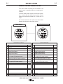
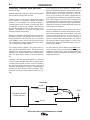
ANALOG CONTROL CABLE K1797-XX
T
he control cable connecting the wire feeder to the
power source is specially made for the welding envi-
ronment.
The wire feeder power requires overcurrent protec-
tion. Connect the wire feeder only to power sources
where the overcurrent protection is no more than 15
amps.
Do not use more than 100 ft. (30.5 m) of control cable
between the wire feeder and power source.
Function
Reserved
Reserved
Welding Output Control
(trigger to power source)
Welding Output Control
(trigger to power source)
Remote Voltage Control
("+" supply, from power source)
Remote Voltage Control
(control signal from feeder or remote.)
Remote Voltage Control
("-" supply, from power source)
Work connection from power source
42 VAC to feeder
Reserved
42 VAC to feeder
Reserved
unused
Electrode voltage to power source
Pin
A
B
C
D
E
F
G
H
I
J
K
L
M
N
Lead #
--
2
4
77
76
75
21
41
42
67
Power Source
POWER SOURCE
WIRE FEEDER
Wire Feeder

A-4
INSTALLATION
RED-D-ARC LN25™ PRO EXTREME DUAL POWER
A-4
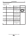
SHIELDING GAS CONNECTION
CYLINDER may explode if
damaged.
• Keep cylinder upright and
chained to support.
• Keep cylinder away from areas where it may be
damaged.
• Never lift welder with cylinder attached.
• Never allow welding electrode to touch cylinder.
• Keep cylinder away from welding or other live
electrical circuits.
• BUILD UP OF SHIELDING GAS MAY
HARM HEALTH OR KILL.
• Shut off shielding gas supply when not
in use.
• See American National Standard Z-49.1, "Safety
in Welding and Cutting” Published by the
American Welding Society.
------------------------------------------------------------------------
Maximum inlet pressure is 100 psi. (6.9 bar.)
Install the shielding gas supply as follows:
1. Secure the cylinder to prevent it from falling.
2. Remove the cylinder cap. Inspect the cylinder valves
and regulator for damaged threads, dirt, dust, oil or
grease. Remove dust and dirt with a clean cloth. DO
NOT ATTACH THE REGULATOR IF OIL, GREASE
OR DAMAGE IS PRESENT! Inform your gas supplier
of this condition. Oil or grease in the presence of high
pressure oxygen is explosive.
3. Stand to one side away from the outlet and open the
cylinder valve for an instant. This blows away any dust
or dirt which may have accumulated in the valve out-
let.
4. Attach the flow regulator to the cylinder valve and
tighten the union nut(s) securely with a wrench. Note:
if connecting to 100% CO
2
cylinder, insert regulator
adapter between regulator and cylinder valve. If
adapter is equipped with a plastic washer, be sure it is
seated for connection to the CO
2
cylinder.
5. Attach one end of the inlet hose to the outlet fitting of
the flow regulator. Attach the other end to the welding
system shielding gas inlet. Tighten the union nuts with
a wrench.
6. Before opening the cylinder valve, turn the regulator
adjusting knob counterclockwise until the adjusting
spring pressure is released.
7. Standing to one side, open the cylinder valve slowly a
fraction of a turn. When the cylinder pressure gage
stops moving, open the valve fully.
8. The flow regulator is adjustable. Adjust it to the flow
rate recommended for the procedure and process
being used before making a weld.
WARNING
WARNING
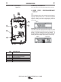
Pin
A
B
C
D
E
Wiring
5 volt supply
Not used
Trigger
83% WFS switch
5 volt supply
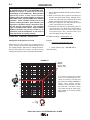
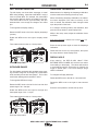
TRIGGER CONNECTIONS
There is one circular connector for the gun trigger on the
front of the RED-D-ARC LN25™ PRO EXTREME DUAL
POWER.
Note – if the gun trigger is already depressed when the
feeder is powered up, the feeder will not activate.
Release and then press the gun trigger to begin welding.
The 83% wire feed speed reduces the wire feed speed to
83% of the original set value when activated. For exam-
ple, if the original wfs = 200 in/min, the feeder will regu-
late to 0.83 x 200 = 166 in/min.
The 83% trigger requires a gun with a dual procedure
switch.
This feature is often useful when welding pipe, and a
“cooler” procedure is required on the bottom portion.
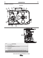
CONTROL CABLE CONNECTOR
The control cable connector is present only on the
Dual Power Feeders.
ELECTRIC SHOCK can kill.
• Do not touch electrically live parts.
• Welding Voltage is present on pins H,
I, K and N when Dual Power feeders
are operating as Accross the Arc
feeder.
Function
5-pin trigger
connector for
push-guns
only.
A
E
C
B
D
Pin
A
B
C
D
E
F
G
H
I
J
K
L
M
N
Picture
Picture
Wiring
Not used
Not used
Output Control to Power Source (2-4)
Output Control to Power Source (2-4)
Remote Voltage Control 77
Remote Voltage Control (wiper) 76
Remote Voltage Control 75
Work Sense Lead 21
42VAC
Not used
42VAC
Not used
Not used
Electrode Sense Lead 67
H
J
A
B
L
C
D
F
E
M
N
K
I
G
WIRE FEEDER

A-5
INSTALLATION
RED-D-ARC LN25™ PRO EXTREME DUAL POWER
A-5
WIRE DRIVE CONFIGURATIONS
ELECTRIC SHOCK can kill.
• Turn the input power OFF at the
welding power source before instal-
lation or changing drive rolls and/or
guides.
• Do not touch electrically live parts.
• When inching with the gun trigger, electrode
and drive mechanism are "hot" to work and
ground and could remain energized several sec-
onds after the gun trigger is released.
• Do not operate with covers, panels or guards
removed or open.
• Only qualified personnel should perform mainte-
nance work.
------------------------------------------------------------------------
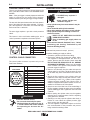
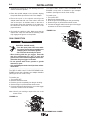
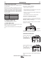
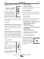
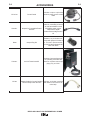
GUN BUSHING, THUMB SCREW AND
SOCKET HEAD CAP SCREW
(See Figure A.2 for Code 11750)
Tools required:
• 1/4" hex key wrench.
Note: Some gun bushings do not require the use of
the thumb screw.
1. Turn power off at the welding power source.
2. Remove the welding wire from the wire drive.
3. Remove the thumb screw from the wire drive.
4. Remove the welding gun from the wire drive.
5. Loosen the socket head cap screw that holds the
connector bar against the gun bushing.
Important: Do not attempt to completely
remove the socket head cap screw.
6. Remove the outer wire guide, and push the gun
bushing out of the wire drive. Because of the pre-
cision fit, light tapping may be required to remove
the gun bushing.
7. Disconnect the shielding gas hose from the gun
bushing, if required.
8. Connect the shielding gas hose to the new gun
bushing, if required.
9. Rotate the gun bushing until the thumb screw hole
aligns with the thumb screw hole in the feed plate.
Slide the gun receiver bushing into the wire drive
and verify the thumb screw holes are aligned.
10. Tighten the socket head cap screw.
11. Insert the welding gun into the gun bushing and
tighten the thumb screw.
GUN RECEIVER BUSHING
LOOSEN TIGHTEN
THUMB SCREW
OUTER WIRE GUI
SOCKET HEAD
CAP SCREW
CONNECTOR BLOCK
WARNING
FIGURE A.2

A-6
INSTALLATION
RED-D-ARC LN25™ PRO EXTREME DUAL POWER
A-6
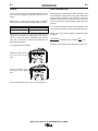
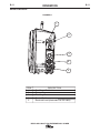
GUN BUSHING, THUMB SCREW AND SET
SCREW
(See Figure A.2a for Code 12164)
The gun bushing is not interchangeable with other
bushings. It is designed to be mechanically mounted
in the feed plate and then bolted directly to the feed-
erʼs internal electrical welding buss bar. It accepts
Magnum Pro guns (Tweco #2 to #4). This bushing
should be removed only for service replacement. It is
secured to the feed plate with an S11604-10 set
screw torqued between 35 to 45 in.-lbs.
Tools required:
• 1/4" hex key wrench, (2) 3/4” Box Wrenches,
3/4” STD. Socket, Adjustable Torque Wrench
(Snap Type)
1. Turn power off at the welding power source.
2. Remove the welding wire from the wire drive.
3. Remove the welding buss bar from the gun bush-
ing assembly.
4. Remove the thumb screw from the wire drive.
5. Remove the welding gun from the wire drive.
6. Loosen set screw.
7. Remove the outer wire guide, and push the gun
bushing out of the wire drive. Because of the pre-
cision fit, light tapping may be required to remove
the gun bushing.
8. Disconnect the shielding gas hose from the gun
bushing.
9. Connect the shielding gas hose to the new gun
bushing.
10. Rotate the gun bushing until the thumb screw hole
aligns with the thumb screw hole in the feed plate.
Slide the gun bushing into the wire drive and verify
the thumb screw holes are aligned.
11. Tighten set screw 35 to 45 in-lbs. (3.95 to
5.08Nm).
12. Connect welding buss bar to gun bushing assem-
bly and tighten bolts to 33 to 44 Ft. Lbs. (44.8 to
59.7Nm).
13. Insert the welding gun into the gun bushing and
tighten the thumb screw.
GUN BUSHING
ASSEMBLY
LOOSEN TIGHTEN
THUMB SCREW
OUTER WIRE GUIDE
SET SCREW
WELDING BUSS
BAR
FIGURE A.2a

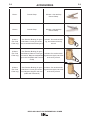
PRESSURE ARM ADJUSTMENT
ELECTRIC SHOCK can kill.
• Turn the input power OFF at the weld-
ing power source before installation or
changing drive rolls and/or guides.
• Do not touch electrically live parts.
• When inching with the gun trigger, electrode
and drive mechanism are "hot" to work and
ground and could remain energized several sec-
onds after the gun trigger is released.
• Do not operate with covers, panels or guards
removed or open.
• Only qualified personnel should perform mainte-
nance work.
------------------------------------------------------------------------
The pressure arm controls the amount of force the
drive rolls exert on the wire. Proper adjustment of the
pressure arm gives the best welding performance.
Many welding problems can be attributed to setting
the pressure arm too high and causing wire deforma-
tion. Set the pressure arm to minimum amount that
provides reliable feeding.
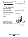
Set the pressure arm as follows:
(See Figure A.3)
Aluminum wires between 1 and 2
Cored wires between 1 and 3
Steel, Stainless wires
between 3 and 5
LOADING SPOOLS OF WIRE
• Keep hands, hair, clothing and tools away from
rotating equipment.
• Do not wear gloves when threading wire
or changing wire spool.
• Only qualified personnel should install,
use or service this equipment.
------------------------------------------------------------------------
Loading 10 to 15 lb. (4.5 – 6.8kg) Spools.
A K468 spindle adapter is required for loading 2"
(51mm) wide spools on 2" (51mm) spindles. Use a
K468 spindle adapter for loading 2-1/2" (64mm) wide
spools.
WARNING
WARNING
6
AL
FCAW
GMAW
FIGURE A.3
A-7
INSTALLATION
RED-D-ARC LN25™ PRO EXTREME DUAL POWER
A-7
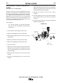
PROCEDURE TO INSTALL DRIVE ROLLS
AND WIRE GUIDES
• Turn the input power OFF at the
welding power source before instal-
lation or changing drive rolls and/or
guides.
• Do not touch electrically live parts.
• When inching with the gun trigger, electrode
and drive mechanism are "hot" to work and
ground and could remain energized several sec-
onds after the gun trigger is released.
• Do not operate with covers, panels or guards
removed or open.
• Only qualified personnel should perform mainte-
nance work.
------------------------------------------------------------------------
1. Turn power off at the welding power source.
2. Release the idle roll pressure arm.
3. Remove the outer wire guide by turning the knurled
thumbscrews counter-clockwise to unscrew them
from the feed plate.
4
. Rotate the triangular lock and remove the drive
rolls.
5. Remove the inner wire guide.
6. Insert the new inner wire guide, groove side out,
over the two locating pins in the feed plate.
7. Install a drive roll on each hub assembly secure
with the triangular lock.
8. Install the outer wire guide by aligning it with the
pins and tightening the knurled thumbscrews.
9. Close the idle arm and engage the idle roll pressure
arm. Adjust the pressure appropriately.
WARNING

THUMB
SCREW
GUN
A-8
INSTALLATION
RED-D-ARC LN25™ PRO EXTREME DUAL POWER
A-8
1. Squeeze the release bar on the retaining collar and
remove it from the spindle.
2. Place the spindle adapter on the spindle, aligning
the spindle brake pin with the hole in the adapter.
3. Place the spool on the spindle and align the
adapter brake tab with one of the holes in the back
side of the spool. An indicator mark on the end of
the spindle shows the orientation of the brake tab.
Be certain the wire feeds off of the spool in the
proper direction.
4. Re-install the retaining collar. Make sure that the
release bar snaps out and that the retaining collar
fully engages the groove on the spindle.
GUN CONNECTION
ELECTRIC SHOCK can kill.
• Turn the input power OFF at the weld-
ing power source before installation or
changing drive rolls and/or guides.
• Do not touch electrically live parts.
• When inching with the gun trigger, electrode
and drive mechanism are "hot" to work and
ground and could remain energized several sec-
onds after the gun trigger is released.
• Do not operate with covers, panels or guards
removed or open.
• Only qualified personnel should perform mainte-
nance work.
------------------------------------------------------------------------
The RED-D-ARC LN25™ PRO EXTREME DUAL
POWER comes with a K1500-2 gun adapter installed.
(See Figure A.4 for Code 11750)
To install a gun,
1. Turn power OFF.
2. Remove the thumb screw.
3. Push the gun the completely into the gun bushing.
4. Secure the gun in place with the thumb screw.
5. Connect the trigger cable from the gun to the trigger
connector on the front of the feeder.
N
ote: Not all gun bushings require the use of the
thumb screw.
The RED-D-ARC LN25™ PRO EXTREME DUAL
POWER comes with an S29807-2 gun adapter
installed. (See Figure A.4a for Code 12164)
To install a gun,
1. Turn power OFF.
2. Remove the thumb screw.
3. Push the gun the completely into the gun bushing.
4. Secure the gun in place with the thumb screw.
5. Connect the trigger cable from the gun to the trigger
connector on the front of the feeder.
WARNING
FIGURE A.4
GUN
THUMB SCREW
FIGURE A.4a

A-9
INSTALLATION
RED-D-ARC LN25™ PRO EXTREME DUAL POWER
A-9
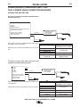
ACROSS THE ARC SET-UPS
CC Power Sources with Output Terminals Always
Hot (See Figure A.5)
If the power source has a Remote/Local switch, place
the switch in the Local position.
Place the CV/CC switch in the feeder in the "CC" posi-
tion.
CV Power Sources with Stud Connectors and
Remote/Local Switch (See Figure A.6)
Place the power source Remote/Local switch in the
Local position.
Place CV/CC switch in the feeder in the "CV" position.
K#
K2614-7
KP1695-XX
KP1696-XX
KP1697-XX
See Magnum Pro Literature
K1803-XX
Description
RED-D-ARC LN25™ PRO
EXTREME DUAL POWER
Drive Roll Kit
Welding Gun
CC power Source
Welding Cables
POWER SOURCE TO RED-D-ARC LN25™ PRO
DUAL POWERR CABLE CONNECTION DIAGRAMS
K#
K2614-7
KP1695-XX
KP1696-XX
KP1697-XX
See Magnum Pro Literature
K1803-XX
K484
Description
RED-D-ARC LN25™ PRO
EXTREME DUAL POWER
Drive Roll Kit
Welding Gun
CV power Source
Welding Cables
Jumper Plug kit
Work clip
Work
Electrode
RED-D-ARC LN25™
PRO EXTREME
DUAL POWER
CC Power Source
Classics
Big Red’s
Eagle 10,000 Plus
Pipeliner 200D Without Wire Feed module
SAE’s Without CV Adapter
SAE 400 with CV adapter
Engine Driven welder with
Wire Feed Module
Work clip
Work
Electrode
Jumper
CV-655
DC-400
DC-600
DC-655
V450-Pro
SAE 400 with CV adapter
Engine Driven welder with
Wire Feed Module
Ranger 250 GXT
RED-D-ARC LN25™
PRO EXTREME
DUAL POWER

A-10
INSTALLATION
RED-D-ARC LN25™ PRO EXTREME DUAL POWER
A-10
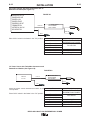
CV Power Sources with Stud Connectors and no
Remote/Local Switch(See Figure A.7)
Place CV/CC switch in the feeder in the "CV" position.
CV Power Source with Twist-Mate Connectors and
Remote/Local Switch. (See Figure A.8)
Place the power source Remote/Local switch in the
Local position.
Place CV/CC switch in the feeder in the "CV" position.
K#
K2614-7
KP1695-XX
KP1696-XX
KP1697-XX
See Magnum Pro Literature
K1803-XX
Description
RED-D-ARC LN25™ PRO
EXTREME DUAL POWER
Drive Roll Kit
Welding Gun
CC power Source
Welding Cables
Work clip
Work
Electrode
RANGER 250, 250 LPG
RANGER 305G, 305D
RANGER 10,000
RANGER 3 PHASE
RANGER225, 225 GXT
COMMANDER 300
VANTAGE 300, 400, 500
AIR VANTAGE 500
RED-D-ARC LN25™
PRO EXTREME
DUAL POWER
FIGURE A.7
V350-Pr
CV 305
o
Work
El ectro de
Work clip
RED-D-ARC LN25™
PRO EXTREME
DUAL POWER
FIGURE A.8
K#
K2614-7
KP1695-XX
KP1696-XX
KP1697-XX
See Magnum Pro Literature
K1841
K852-95
Description
RED-D-ARC LN25™ PRO
EXTREME DUAL POWER
Drive Roll Kit
Welding Gun
CV power Source
Welding Cables
Twist-Mate Cable Plug

A-11
INSTALLATION
RED-D-ARC LN25™ PRO EXTREME DUAL POWER
A-11
CV Power Source with Twist-Mate Connectors and
no Remote/Local Switch. (See Figure A.9)
Place CV/CC switch in the feeder in the "CV" position.
CV-250
CV-300
Work
El ectro de
Jum p e
r
Work clip
RED-D-ARC LN25™
PRO EXTREME
DUAL POWER
FIGURE A.9
K#
K2614-7
KP1695-XX
KP1696-XX
KP1697-XX
See Magnum Pro Literature
K1841-XX
K852-95
K484
Description
RED-D-ARC LN25™ PRO
EXTREME DUAL POWER
Drive Roll Kit
Welding Gun
CV power Source
Welding Cables
Twist-Mate Cable Plug
Jumper Plug kit
CONTROL CABLE SET-UPS
CV Power Source with 24-42 VAC
(See Figure A.10)
If present, place the power source
Remote/Local Switch in the Remote
position.
Place CV/CC switch in the feeder in
the "CV" position.
CV Power Source
CV-305
CV-400
CV-655
DC-400
DC-655
V-350
V-450
Work
Electrode
Control Cable
VANTAGE 300, 400, 500
RANGER 250, 305
ENGINE DRIVE WITH
WIRE FEED MODULE
SAE’s WITH K385-2
RED-D-ARC LN25™
PRO EXTREME
DUAL POWER
K#
K2614-7
KP1695-XX
KP1696-XX
KP1697-XX
K1797-xx
K2335-1
See Magnum Pro Literature
KP1803-XX
K852-95
Description
RED-D-ARC LN25™ PRO
EXTREME DUAL POWER,
Drive Roll Kit
Control Cable
Adapter for Competitive Power Sources
Welding Gun
CV power source
Welding Cables
Twist-Mate Cable Plug
FIGURE A.10
ELECTRIC SHOCK CAN KILL.
• When the wire feeder is connected to the power source with the control cable, the
contactor in the wire feeder is always closed and the wire drive and the gun may be at
welding potential.
WARNING
La page est en cours de chargement...
La page est en cours de chargement...
La page est en cours de chargement...
La page est en cours de chargement...
La page est en cours de chargement...
La page est en cours de chargement...
La page est en cours de chargement...
La page est en cours de chargement...
La page est en cours de chargement...
La page est en cours de chargement...
La page est en cours de chargement...
La page est en cours de chargement...
La page est en cours de chargement...
La page est en cours de chargement...
La page est en cours de chargement...
La page est en cours de chargement...
La page est en cours de chargement...
La page est en cours de chargement...
La page est en cours de chargement...
La page est en cours de chargement...
La page est en cours de chargement...
La page est en cours de chargement...
La page est en cours de chargement...
La page est en cours de chargement...
La page est en cours de chargement...
La page est en cours de chargement...
La page est en cours de chargement...
La page est en cours de chargement...
-
 1
1
-
 2
2
-
 3
3
-
 4
4
-
 5
5
-
 6
6
-
 7
7
-
 8
8
-
 9
9
-
 10
10
-
 11
11
-
 12
12
-
 13
13
-
 14
14
-
 15
15
-
 16
16
-
 17
17
-
 18
18
-
 19
19
-
 20
20
-
 21
21
-
 22
22
-
 23
23
-
 24
24
-
 25
25
-
 26
26
-
 27
27
-
 28
28
-
 29
29
-
 30
30
-
 31
31
-
 32
32
-
 33
33
-
 34
34
-
 35
35
-
 36
36
-
 37
37
-
 38
38
-
 39
39
-
 40
40
-
 41
41
-
 42
42
-
 43
43
-
 44
44
-
 45
45
-
 46
46
-
 47
47
-
 48
48


Lincoln Electric Red-D-Arc LN-25 Pro Extreme Mode d'emploi
- Catégorie
- Système de soudage
- Taper
- Mode d'emploi
dans d''autres langues
Documents connexes
-
Lincoln Electric Red-D-Arc EX350ie Mode d'emploi
-
-
-
-
-
-
-
Lincoln Electric Ranger 305D Mode d'emploi
-
-