Generac 8 kW 0056100 Manuel utilisateur
- Catégorie
- Groupes électrogènes
- Taper
- Manuel utilisateur

INSTALLATION
GUIDELINES
Air-cooled Generators

TABLE OF CONTENTS
Introduction ..................................................Inside Front Cover
General Hazards ................................................................... IFC
Generator Installation ............................................................... 1
Before Installation ...................................................................... 1
NFPA Standards ......................................................................... 1
Other Published Standards ....................................................... 1
Grounding the Generator .......................................................... 2
Battery Installation ....................................................................2
Vented Batteries ......................................................................... 2
Before You Begin ........................................................................2
Site Preparation and Generator Placement .............................2
Coverting to LP Vapor ............................................................... 3
Installing & Connecting Gas Lines .......................................... 4
Battery Charger Installation ..................................................... 5
External Electrical Connections ............................................... 6
Generator Connections - RTS Load Center
Transfer Switch ....................................................................... 6
Appendix A - RTS Pre-wired Load Center Transfer
Switch Installation & Operational Testing ........................... 8
Battery Installation .................................................................. 9
Operational Testing ............................................................... 10
Appendix B - RTSN Nd RTSE Transfer Switch
Installation & Operational Testing ...................................... 12
Selected Circuit Coverage ..................................................... 12
Whole-house Circuit Coverage ............................................. 13
Battery Charger Installation .................................................. 13
Electrical Connections .......................................................... 13
Operational Testing ............................................................... 14
Appendix C - PowerMaster™ Load Controller
Installation and Operationa Testing .................................... 16
Operational Testing ............................................................... 17
Checking the Priority Load Controller .................................. 20
Appendix D - PowerManager™ Load Shed Transfer
Switch Installation and Operational Testing ...................... 21
Battery Charger Installation .................................................. 22
Electrical Connections .......................................................... 22
Operational Testing ............................................................... 24
Verifying Load Shedding Operation ..................................... 25
Appendix E - GenReady™ Load Center Installation
and Operational Testing ....................................................... 28
Battery Charger Installation .................................................. 28
Electrical Connections .......................................................... 29
Operational Testing ............................................................... 30
Appendix F - Setting the Automatic Exercise
Function ................................................................................. 32
Notes .......................................................................................... 34
Electrical Data .......................................................................... 36
INTRODUCTION
This booklet and the accompanying video are designed to famil-
iarize personnel with the installation process for air-cooled gen-
erators. This booklet does not replace or supersede any informa-
tion contained in any of the other written documents shipped with
the equipment. This booklet should only be use in conjunction
with the Owner’s Manual, Installation Guide and other technical
documents shipped with the equipment.
Future product updates and/or modifi cations will be refl ected in
the written documentation included with Generac equipment.
Always read all accompanying documentation carefully before
attempting to install any generator, transfer switch or related
equipment.
It is essential to comply with all regulations established by the
Occupational Safety and Health Administration (OSHA) and
strict adherence to all local, state and national codes is mandatory.
Study the SAFETY RULES in the Owner’s Manual carefully
before installing, operating or servicing any equipment. Use
this guide ONLY in conjunction with the Owner’s Manual and
Installation Guide shipped with the generator. The generator
can operate safely, effi ciently and reliably only if it is properly
installed, operated and maintained.
The manufacturer cannot anticipate every possible circumstance
that might involve a hazard. The warnings in this manual, and on
tags and decals affi xed to the unit are, therefore, not all-inclusive.
Despite the safe design of this generator, operating this
equipment imprudently, neglecting its maintenance or being
careless can cause possible injury or death.
Permit only responsible and capable persons to install, operate or
maintain this equipment.
Potentially lethal voltages are generated by these machines.
Ensure all steps are taken to render the machine safe before
attempting to work on the generator.
Caution, risk of electrical shock! The neutral conductor must
be bonded to ground in accordance with the National Electrical
Code, NFPA 70. This unit shall not be used in fl oating output
applications.
GENERAL HAZARDS
For safety reasons, the manufacturer recommends that this equipment
be installed, serviced and repaired by a Service Dealer or other
competent, qualifi ed electrician or installation technician who is
familiar with applicable codes, standards and regulations. The operator
also must comply with all such codes, standards and regulations.
Installation, operation, servicing and repair of this (and related)
equipment must always comply with applicable codes, standards,
laws and regulations. Adhere strictly to local, state and national
electrical and building codes. Comply with regulations the
Occupational Safety and Health Administration (OSHA) has
established. Also, ensure that the generator is installed, operated
and serviced in accordance with the manufacturer’s instructions

1
and recommendations. Following installation, do nothing that
might render the unit unsafe or in noncompliance with the
aforementioned codes, standards, laws and regulations.
Engine exhaust fumes contain carbon monoxide gas, which
can be DEADLY. This dangerous gas, if breathed in suffi cient
concentrations, can cause unconsciousness or even death. For
that reason, adequate ventilation must be provided. Exhaust gases
must be piped safely away from any building or enclosure that
houses the generator to an area where people, animals, etc., will
not be harmed. This exhaust system must be installed properly, in
strict compliance with applicable codes and standards.
Keep hands, feet, clothing, etc., away from drive belts, fans, and
other moving or hot parts. Never remove any drive belt or fan
guard while the unit is operating.
Adequate, unobstructed fl ow of cooling and ventilating air is
critical to prevent buildup of explosive gases and to ensure
correct generator operation. Do not alter the installation or
permit even partial blockage of ventilation provisions, as this can
seriously affect safe operation of the generator. Never install a
generator indoors.
Keep the area around the generator clean and uncluttered. Remove
any materials that could become hazardous. When working on this
equipment, remain alert at all times. Never work on the equipment
when physically or mentally fatigued.
GENERATOR INSTALLATION
These generators are air-cooled, engine-driven generator sets
designed to supply electrical power that operates critical electrical
loads during utility power failure. These generators are factory-
installed in a weather resistant, all metal enclosure and are intended
for outdoor installation only.
BEFORE INSTALLATION
The generator’s rated wattage/amperage capacity must be adequate to
handle all electrical loads that the unit will power. The critical priority
loads may need to be grouped together and wired into a separate
priority circuits distribution panel.
Each generator has a minimum fuel volume requirement. Refer
to the owner’s manuals for the generator fuel consumption.
Verify that the natural gas meter presently installed at the house
will support both the generator fuel load as well as any other
gaseous appliances that will require
fuel to operate if powered by
the generator. If an LP application,
verify that the fuel tank and pipe
is large enough to sustain the necessary volume even during cold
temperatures.
Connecting this generator to an electrical system normally
supplied by an electric utility shall be by means of a transfer
switch, so as to isolate the electric system from the utility
distribution system when the generator is operating. Failure to
isolate the electric system by these means will result in damage
to the generator and may also result in injury or death to utility
workers due to backfeed of electrical energy.
The engine-generator is to be installed over non-combustible
materials and should be located such that combustible materials
are not capable of accumulating under the generator set.
Only qualifi ed, competent installation contractors or electricians
thoroughly familiar with applicable codes, standards and
regulations should install this standby electric power system. The
installation must comply strictly with all codes, standards and
regulations pertaining to the installation.
After the system has been installed, do nothing that might render
the installation in non-compliance with such codes, standards and
regulations.
NFPA STANDARDS
The following published standards booklets pertaining to standby
electric systems are available from the National Fire Protection
Association (NFPA), Batterymarch Park, Quincy, MA 02269:
NFPA No. 37, STATIONARY COMBUSTION
ENGINES AND GAS TURBINES
NFPA No. 54, NATIONAL FUEL GAS CODE
NFPA No. 58, LIQUIFIED PETROLEUM GAS CODE
NFPA 70, National Electrical Code (NEC)
NFPA 99, STANDARD FOR HEALTH CARE
FACILITIES
NFPA 101, LIFE SAFETY CODE
NFPA 110, STANDARD FOR EMERGENCY AND
STANDBY POWER SYSTEMS
NFPA 220, STANDARD TYPES OF BUILDING
CONSTRUCTION
NOTE: It is essential to use the latest version of any standard to
ensure that the generator and its accessories comply with all the
applicable standards and local codes.
OTHER PUBLISHED STANDARDS
In addition to NFPA standards, the following information
pertaining to the installation and use of standby electric systems
is available:
Article X, NATIONAL BUILDING CODE, available •
from the American Insurance Association, 85 John Street,
New York, N.Y. 10038.
AGRICULTURAL WIRING HANDBOOK, obtainable •
from the Food and Energy Council, 909 University
Avenue, Columbia, MO, 65201.
ASAE EP-364.2, INSTALLATION AND •
MAINTENANCE OF FARM STANDBY ELECTRIC
POWER, available from the American Society of
Agricultural Engineers, 2950 Niles Road, St. Joseph, MI
49085.
A52.1, AMERICAN NATIONAL STANDARDS
•
FOR CHIMNEYS, FIREPLACES AND VENTING
SYSTEMS, available from the American National
Standards Institute, 1430 Broadway, New York, NY
10018.
The installer must comply with all applicable state and local
codes.

2
GROUNDING THE GENERATOR
A grounding lug is provided on the generator mounting base for
the purpose of grounding the frame and the external electrically
conductive parts of this equipment to an approved earth ground
and/or grounding rods where required by the National Electrical
Code. Grounding procedures must meet local regulations.
BATTERY INSTALLATION
Standby generators installed with automatic transfer switches will
crank and start automatically when NORMAL (UTILITY) source
voltage is removed or is below an acceptable preset level. To
prevent such automatic start-up and possible injury to personnel,
do not connect battery cables until certain that normal source
voltage at the transfer switch is correct and the system is ready to
be placed into operation.
Storage batteries give off explosive hydrogen gas. This gas can
form an explosive mixture around the battery for several hours
after charging. The slightest spark can ignite the gas and cause
an explosion. Such an explosion can shatter the battery and
cause blindness or other injury. Any area that houses a storage
battery must be properly ventilated. Do not allow smoking, open
fl ame, sparks or any spark producing tools or equipment near the
battery.
Battery electrolyte fl uid is an extremely caustic sulfuric acid
solution that can cause severe burns. Do not permit fl uid to
contact eyes, skin, clothing, painted surfaces, etc. Wear protective
goggles, protective clothing and gloves when handling a battery.
If fl uid is spilled, fl ush the affected area immediately with clear
water.
Do not dispose of the battery in a fi re. The battery is capable of
exploding.
Do not open or mutilate the battery. Released electrolyte can be
toxic and harmful to the skin and eyes.
The battery represents a risk of high short-circuit current. When
working on the battery, always remove watches, rings or other
metal objects, and only use tools that have insulated handles.
VENTED BATTERIES
The electrolyte is a dilute sulfuric acid that is harmful to the
skin and eyes. It is electrically conductive and corrosive. The
following procedures are to be observed:
Wear full eye protection and protective clothing.•
If electrolyte contacts the skin, wash it off immediately with •
water.
If electrolyte contacts the eyes, fl ush thoroughly and •
immediately with water and seek medical attention. Spilled
electrolyte is to be washed down with an acid-neutralizing
agent. A common practice is to use a solution of one pound
(500 grams) bicarbonate of soda to one gallon (4 liters) of
water. The bicarbonate of soda solution is to be added until the
evidence of reaction (foaming) has ceased. The resulting liquid
is to be fl ushed with water and the area dried.
Lead acid batteries present a risk of fi re because they generate •
hydrogen gas. The following procedures are to be followed:
DO NOT SMOKE when near batteries.•
DO NOT cause fl ame or spark in battery area.•
Discharge static electricity from body before touching batteries •
by fi rst touching a grounded metal surface.
Servicing of batteries is to be performed or supervised •
by personnel knowledgeable of batteries and the required
precautions. Keep unauthorized personnel away from batteries.
For recommended batteries, see the Installation Guide. All •
batteries must be at 100 percent state of charge before they are
installed on the generator.
It is important to check the specifi c gravity and electrolyte •
level. Have these procedures performed at the intervals
specifi ed in the “Maintenance” section in the Owner’s Manual.
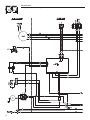
A negative ground system is used. Battery connections are
shown on the wiring diagrams. Make sure all batteries are
correctly connected and terminals are tight. Observe battery
polarity when connecting batteries to the generator set.
NOTE: Damage could result if the battery connections are made
in reverse.
BEFORE YOU BEGIN
Contact the local inspector or City Hall to be aware of all federal,
state and local codes that could impact the installation. Secure all
required permits before starting the job.
Carefully read and follow all of the procedures and safety
precautions detailed in the installation guide. If any portion of the
installation manual, technical manual or other factory-supplied
documents is not completely understood, contact a dealer for
assistance.
Fully comply with all relevant NEC, NFPA and OSHA standards
as well as all federal, state and local building and electric codes.
As with any generator, this unit must be installed in accordance
with current NFPA 37 and NFPA 70 standards as well as any
other federal, state, and local codes for minimum distances from
other structures.
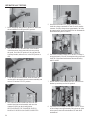
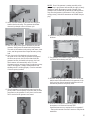
SITE PREPARATION AND GENERATOR
PLACEMENT
1. Locate the mounting area as close as possible to the transfer
switch and fuel supply.

3
Leave adequate room around the area for service access
(check local code), and place high enough to keep rising
water from reaching the generator.
Choose an open space that will provide adequate and
unobstructed airfl ow.
2. Place the unit so air vents won’t become clogged with
leaves, grass, snow or debris. Make sure exhaust fumes
will not enter the building through eaves, windows,
ventilation fans or other air intakes.
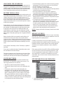
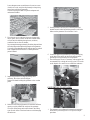
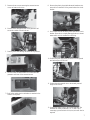
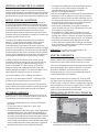
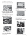
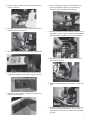
Dig a rectangular area approximately fi ve inches deep and about
six inches longer and wider than the footprint of the generator.
Cover with polyurethane fi lm and fi ll with pea gravel or crushed
stone. Compact and level the stone. A concrete pad can be
poured if desired.
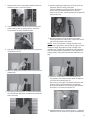
3. Inspect the generator for shipping damage and if
necessary, fi le a claim with the shipper.
Remove the bands holding the generator to the wooden
pallet.
4. Make sure the lifting equipment to be used has suffi cient
capacity to safely handle the weight of the generator.
Use nylon lifting straps and connect them to the lifting
eyes on each corner of the base frame to avoid damaging
the enclosure.
5. Set the generator onto the pad so that the gravel bed
extends several inches beyond the generator on all sides.
Make sure the generator is level within ½ inch.
6. Connect an approved ground strap to the grounding lug
on the base frame and to an approved earth ground or
grounding rod as specifi ed by local regulations.
7. Check the engine oil and, if necessary, add enough of the
recommended oil to bring the level up to the FULL mark
on the dipstick. Be careful not to overfi ll the crankcase.
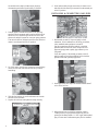
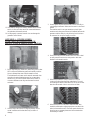
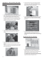
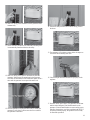
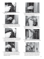
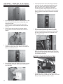
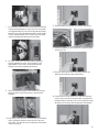
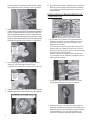
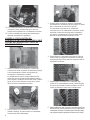
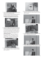
CONVERTING TO LP VAPOR
1. The generator was confi gured for natural gas operation
at the factory. Switching over to LP Vapor is a simple
procedure.

4
On models with a single cylinder engine, begin by
disconnecting and removing the battery if installed.
2. Take the plastic T-handle fuel selector in the poly bag
supplied with the generator and locate the selector tab on
the air box cover. Insert the pin end into the hole in the
selector tab and pull outward to overcome spring pressure.
Then twist clockwise 90 degrees and allow the selector to
return in once aligned with the LP position.
3. On 10 kW units, open the roof, loosen the forward clamp
on the air inlet hose, and slide the hose away from the
hose fi tting.
4. Slide the fuel selector pin on the carburetor out towards
the back of the enclosure.
5. Replace the inlet hose and tighten the clamp securely.
6. On all other models, simply remove the air cleaner cover
and slide the fuel selector pin outward from the natural gas
to the LP position.
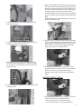
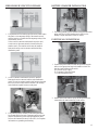
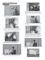
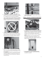
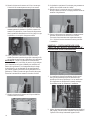
INSTALLING & CONNECTING GAS LINES
1. Both natural gas and LP Vapor are highly volatile
substances, so strict adherence to all safety procedures,
codes, standards and regulations is essential.
Gas line connections should be made by a certifi ed
plumber familiar with local codes. Always use AGA-
approved gas pipe and a quality pipe sealant or joint
compound.
Verify the capacity of the natural gas meter or the LP
tank in regards to providing suffi cient fuel for both the
generator and other operating appliances.
2. Most applications will require an external manual shutoff
valve on the fuel line.
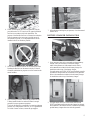
3. Where the gas line is to enter the generator, install a
T-fi tting to allow for gas pressure monitoring. On one
opening of the fi tting install a ¼” NPT nipple and threaded
plug. In some cases a sediment trap may also be installed.

5
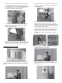
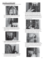
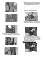
4. When connecting the gas line to the generator, use the
provided section of UL Listed or AGA-approved fl exible
fuel line in accordance with local regulations. The
purpose of the fl exible fuel line is to ensure that vibration
from the generator does not cause a gas leak at one of
the connection points, so it’s important that the line be
installed with as few bends as possible.
5. Never bend the fl exible fuel line to avoid using an elbow.
Bending the fl exible line decreases its ability to absorb
vibrations and defeats its purpose as well as constricts the
actual fuel fl ow.
6. After checking for leaks, check the gas pressure at the
T-fi tting installed earlier to make sure there’s enough
pressure for proper generator operation.
The local gas supplier is responsible for ensuring adequate
pressure, so if the pressure is too low, or if it’s greater than
14 inches of water column, contact the gas supplier.
7. When fi nished checking the gas pressure, close the manual
shutoff valve.
BATTERY CHARGER INSTALLATION
1. If the generator came with a separately packaged battery
charger, it may be necessary to install the charger,
either in
the generator or in the transfer switch. Refer
to documentation
included with the battery charger for
installation and wiring of the battery charger.
For applications with RTSN, RTSE and GenReady transfer
switches the charger needs to be mounted in the generator.
Refer to documentation included with the battery charger
for installation and wiring of the battery charger.
2. For applications with RTS Load Center switches and
RTSS Load Shed transfer switches the charger has already
been installed in the transfer switch. Discard the separately
packed battery charger that came with the generator.

6
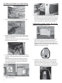
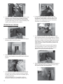
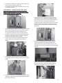
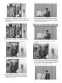
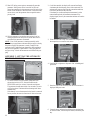
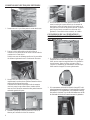
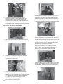
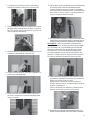
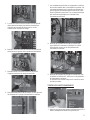
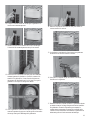
EXTERNAL ELECTRICAL CONNECTIONS
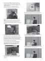
1. Drill a 1 ¾ inch hole and feed the conduit through the hole.
2. Remove the knockout in the back of the connection box,
feed the wires through the back of the box and secure the
conduit with the lock nut.
Seal the hole with silicone caulk. Don’t forget to caulk the
hole inside the house as well.
3. Mount the connection box so that it completely covers the hole
in the wall. Caulk around the sides and top of the box to ensure a
good seal.
Connect all wires to the lugs in the connection box (black to
black, red to red and white to white). Attach the green ground
wire to the ground screw and connect the two small plugs to
their mating receptacle ends.
4. Replace the protective cover plate and retaining screw, and
lock the connection box.
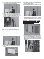
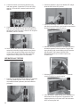
5. For 10-20 kW models, locate the metal hasp that is
packaged in the owner’s manual bag. Insert the hasp in the
slot located on the left side of the external circuit breaker
box. Be sure that the clip of the hasp is facing toward the
front of the generator. If desired, lock the external box.
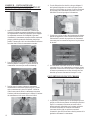
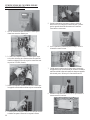
GENERATOR CONNECTIONS – RTS LOAD
CENTER TRANSFER SWITCH
1. If the generator comes with an external connection box
and 5’ seal-tite whip pre-wired and connected to the
generator, no additional connections are necessary at the
generator. Skip the following section and proceed with
Appendix A, RTS Pre-Wired Load Center Transfer Switch
Installation & Operational Testing.
2. If the RTS Load Center transfer switch was purchased
separately from the generator, the 5’ seal-tite whip will
need to be connected to the generator. To complete the
wiring, run the ¾” conduit for the power leads and control
wires from the external connection box to the generator.

7
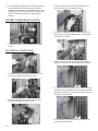
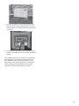
3. Remove the two screws securing the connection area
cover, and remove the cover.
4. Feed the wires through the back of the generator and
secure the conduit with the lock nut.
5. Run the power leads through the strain relief provided.
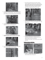
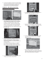
6. On 8 kW units, the main breaker is located inside the
generator at the rear of the connection area.
7. For all other models the circuit breaker is attached to the
exterior access panel.
8. Remove the plastic plugs inside the main breaker access
area to allow connection of the power leads to the circuit
breaker.
9. Now connect the red and black power leads to the circuit
breaker. Since this is a single-phase application, it doesn’t
matter which wire is connected to which lug.
10. Connect the green equipment ground wire to the ground
stud and torque to 80 inch lbs.
11. Connect the white neutral wire to the neutral post and
torque to 80 inch lbs.
12. Connect the control wires to the correct terminals. The
terminals are clearly marked N1, N2, 23 and 15B. If
connecting a pre-wired switch a 0 (zero) wire will also be
required.

8
13. If the battery charger was factory mounted in the transfer
switch, 0 (zero) will also need to be connected between
the generator and transfer switch.
14. An improperly connected control wire can damage the
generator control board.
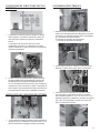
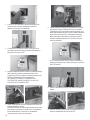
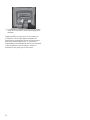
APPENDIX A – RTS PRE-WIRED
LOAD CENTER TRANSFER SWITCH
INSTALLATION & OPERATIONAL TESTING
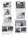
1. Before beginning any installation, make sure power is shut
OFF to the main distribution panel and carefully read the
Owner’s Manual that came with the transfer switch.
The distributed load center switch must be mounted close
enough to the main distribution panel to accommodate
the two-foot, pre-wired conduit. Make sure no water or
corrosive substances can drip onto the transfer switch
enclosure.
2. Always inspect the switch for shipping damage. Never
mount a transfer switch that shows any evidence of
damage.
3. Protect against impact and mount the switch vertically to
a rigid support structure. Make sure the switch is level and
plumb.
The transfer switch is an open transition switch. Open
transition switches prevent electrical feedback between the
generator and the utility by only allowing load circuits to
be connected to one power supply at a time.
4. Each wire in the pre-wired transfer switch is color-coded
to easily match circuits in the main panel to their new
breakers in the transfer switch.
5. When three-conductor wiring is used, two 120 volt
circuits will often share the same neutral wire. To avoid
overloading the neutral, either move BOTH of the circuits
that share the neutral or don’t move either of them.
6. When moving two circuits with a shared neutral, they
should be connected to adjacent positions (one above the
other) in the transfer switch. That will assure that the two
hot wires are on separate phases and will maintain their
relationship to neutral.

9
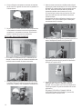
7. Choose a circuit to be backed up and remove the power
lead from the breaker.
8. Using UL Listed wire nuts, reconnect the power lead to a
matching breaker in the transfer switch.
9. Make sure each circuit moved is protected by the same
size breaker in the transfer switch. 15 Amp circuits must
be connected to 15 Amp breakers and 20 Amp circuits to
20 Amp breakers.
10. Connect the provided large neutral to the neutral bar in the
distribution panel.
11. Install a 2-pole breaker in the distribution panel to protect
the transfer switch. The required amp rating of the breaker
depends on which transfer switch is used. If installing an
8-circuit, pre-wired load center switch, the breaker cannot
exceed 40 Amps. For all other pre-wired load center
switches the breaker cannot exceed 70 Amps. This breaker
must be compatible with the existing electrical distribution
panel.
Install the breaker in two adjacent empty slots (one above
the other) in the main panel.
12. When all priority circuits have been moved to the transfer
switch, close the main breaker to restore utility power and
make sure utility voltage at the transfer switch is correct.
Refer to NFPA 70-E for the safety equipment required
when working inside a live transfer switch.
13. Before purchasing a battery for the generator, refer to
the generator Owner’s Manual for a list of recommended
batteries. Follow all of the procedures and safety
precautions in the Owner’s Manual when installing the
battery.
BATTERY INSTALLATION
1. Before purchasing a battery for the generator, refer to the
Owner’s Manual for the recommended battery.
• 8 kW: Group 26R, 12 Volt, 350cca minimum
• 10-20 kW: Group 26R, 12 Volt, 525cca minimum

10
2. Follow all of the procedures and safety precautions in the
generator Owner’s Manual when installing the battery.
Verify the switch is in the off position. When preparing
for operational testing, DO NOT connect the battery until
transfer switch connections are complete.
OPERATIONAL TESTING
1. Switch the generator’s main circuit breaker OFF and put
the mode switch in the OFF position.
2. Make sure utility power is OFF and place all of the
priority circuit breakers in the transfer switch in the OFF
position.
3. Locate the transfer handle, insert the metal end into the
slot in the main contactor assembly and pull the handle
DOWN to move the main contacts to the standby power,
or generator position.
NEVER OPERATE THE TRANSFER SWITCH
MANUALLY WHEN LOADS ARE CONNECTED.
4. Put the generator’s mode switch in MANUAL to start
the engine.
Allow the engine to warm up, then switch
the generator’s main breaker to the ON position. The
generator is now supplying electricity to the transfer
switch but is not carrying any load.
5. For all models except the 8 and 10kW check to be sure
that voltage and frequency from the generator is correct. If
line-to-line voltage is not approximately 240 volts, refer to
the Owner’s Manual for the proper adjustment procedures.
On all models, if line-to-neutral voltage is not 120 volts,
check the neutral connection between the generator and
transfer switch.
For 8 kW models check to be sure that the frequency
from the generator is correct. If the frequency is not
approximately 60Hz, refer to the generator Owner’s
Manual for the proper adjustment procedure.
6. When fi nished checking the voltage, switch the generator’s
main circuit breaker OFF and put the mode switch in the
OFF position to shut down the generator.

11
7. Make sure the 2-pole circuit breaker installed in the main
distribution panel is in the OFF position.
8. Use the transfer handle to move the main contacts in the
transfer switch to the UP (utility position). Switch the
2-pole breaker ON in the distribution panel.
9. Now switch the generator’s main breaker ON, and put the
mode switch in AUTO.
10. Shut OFF utility power and make sure the generator starts
automatically.
11. If everything worked properly, switch the main breaker to
ON and make sure that power is automatically transferred
back to the utility.
12. After the engine has completed its cool down cycle and
shut down, shut OFF utility power again.
When the generator is supplying power to the transfer
switch, move the breakers in the switch to the ON
position, one at a time, until the generator has accepted the
entire priority load.
13. With the generator carrying the entire priority load,
recheck gas pressure to verify that it is at the same level it
was before the generator was started.
NOTE: Even if the generator is running smoothly at this
point, a drop in gas pressure indicates that the supply is barely
adequate to supply the generator’s needs. Changes in the
generator load, or additional gas demand by other appliances
may affect the generator’s performance. Verify gas pressure
and pipe sizing.
Unhook the manometer and reinstall the port
plug.
14. Switch the main breaker ON to restore utility power.
The generator will continue to run to allow the engine to
cool down before shutting itself off.
Shut off utility power again. The generator should start and
the entire priority load should transfer to the generator.
Close the main breaker to restore utility power and allow
the engine to cool down and shut itself off.
15. Operational tests are now complete. Refer to – Setting the
Automatic Exercise Function to complete the installation.

12
APPENDIX B – RTSN AND RTSE TRANSFER
SWITCH INSTALLATION & OPERATIONAL
TESTING
1. Before beginning any installation, make sure power is shut
OFF to the main distribution panel and carefully read the
Owner’s Manual that came with the transfer switch.
To simplify the installation process, the transfer switch
should be mounted as close to the main distribution panel
as possible. Make sure no water or corrosive substances
can drip onto the transfer switch enclosure.
2. Always inspect the switch for shipping damage. Never
mount a transfer switch that shows any evidence of
damage.
3. Protect against impact and mount the switch vertically to a
rigid support structure. Make sure the switch is level and
plumb.
Check local codes before wiring the transfer switch. Some
jurisdictions require that wiring inside the switch be done
by a licensed electrician.
4. All wiring must be the correct size and type, and must
conform to all codes, standards and regulations. Refer
to the transfer switch Owner’s Manual and the National
Electrical Code for additional information.
5. As with any product, design changes can occur over time,
so always refer to the schematics in the transfer switch
Owner’s Manual for the required connections and safety
precautions.
6. The transfer switch being used is an open transition
switch. Open transition switches prevent electrical
feedback between the generator and the utility by only
allowing load circuits to be connected to one power supply
at a time.
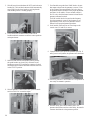
SELECTED CIRCUIT COVERAGE
1. The generator powers only designated circuits that are
grouped together and wired into a separate priority
distribution panel. The transfer switch is installed between
the main distribution panel and the priority panel.
The amperage rating of the transfer switch must be equal
to or greater than the highest amperage rating of the utility
and generator breakers feeding the switch.

13
WHOLE-HOUSE CIRCUIT COVERAGE
1. The generator will be backing up all electrical loads within
the panel, so the amperage rating of the transfer switch
must be equal to or greater than the amperage rating of the
normal utility service.
Unless a service entrance rated transfer switch is used,
a main service disconnect must be located before the
transfer switch. The transfer switch must be installed
between the utility service entrance and the building
distribution panel.
2. A service entrance rated transfer switch is installed
between the service entrance and the main distribution
panel. The service entrance rated switch becomes the main
service so no service disconnect is needed. The existing
main distribution panel becomes a sub-panel.
3. The grounding that is normally in the main panel must
be accomplished in the service entrance rated switch and
must be disconnected in the existing distribution panel.
Refer to the National Electrical Code (NEC) for complete
information on grounding and bonding.
BATTERY CHARGER INSTALLATION
1. The battery charger is to be installed in the generator when
using an RTSN or RTSE transfer switch. Refer to the
Battery Charger Installation Guide for details.
ELECTRICAL CONNECTIONS
1. Connect the power leads from both the generator and the
utility to the appropriate lugs in the transfer switch. The
lugs are clearly marked in the switch.
N = Normal Utility Supply
E = Generator Connection Panel
T = Load Distribution Panel
2. Neutral wires from both the utility and the generator are
connected to the same neutral lug in the switch.

14
3.
Connect the control wires from the generator to the terminal
block in the transfer switch. The terminals are marked N1,
N2, 23 and (194 or 15B). If the fourth terminal in the transfer
switch is labeled 194, wire 15B from the generator will
connect to terminal 194 in the transfer switch.
4. Complete the transfer switch wiring by connecting the
equipment ground wires from both the utility and the
generator to the ground lug.
5. Being careful to support the lugs, torque the lugs in the
transfer switch to the specifi cations shown on the transfer
switch. Decal located on the inside of the switch door.
OPERATIONAL TESTING
1. If installing the RTSE switch, the service was changed so
make sure the terminations are good before re-energizing the
utility.
2 Switch the main utility breaker OFF. Refer to NFPA 70-E
for the safety equipment required when working inside a
live transfer switch.
3. Energize the utility and check line-to-line and line-to-
neutral voltage at terminals N1 and N2 on the transfer
contactor. If line-to-line voltage is not approximately 240
volts, de-energize utility power and check the terminations
between the utility and N1 and N2.
If line-to-neutral voltage is not approximately 120 volts, de-
energize utility power and check the neutral terminations.
Repeat the same voltage checks on terminals T1 and
T2 to make sure current is fl owing properly through the
contactor.
4. Switch the generator’s main circuit breaker OFF and put
the mode switch in the OFF position.
5. Make sure utility power is OFF and place all of the
individual
circuit
breakers in the main distribution panel in
the OFF position.

15
6. Locate the transfer handle, insert the metal end into
the slot in the main contactor assembly. Pull the handle
DOWN to move the main contacts to the standby power
(generator) position.
NEVER OPERATE THE TRANSFER SWITCH
MANUALLY WHEN LOADS ARE CONNECTED.
7. Put the generator’s mode switch in MANUAL to start the
engine.
Allow the engine to warm up, then switch the generator’s
main breaker to the ON position. The generator is now
supplying electricity to the transfer switch but is not carrying
any load.
8. For all models except the 8 and 10 kW check to be sure
that voltage and frequency from the generator is correct.
If line-to-
line voltage is not approximately 240 volts, refer
to the generator
Owner’s Manual for the proper adjustment
procedures. On all models, if line-to-neutral voltage is
not approximately 120 volts, check the neutral connection
between the generator and transfer switch.
For 8 kW models check to be sure that the frequency
from the generator is correct. If the frequency is not
approximately 60Hz, refer to the generator Owner’s
Manual for the proper adjustment procedure.
9. Switch the generator’s main circuit breaker OFF and put
the mode switch in the OFF position to shut down the
generator.
10. With utility power still OFF, use the transfer handle to
move the main contacts to the UP (utility) position.
11. Close the main breaker to turn utility power ON.
12. Switch the generator’s main breaker to the ON position
and put the mode switch in AUTO.
13. Shut OFF utility power and make sure the generator starts
automatically after the line interrupt delay.

16
14. Switch the utility breaker to ON and make sure that power
is automatically transferred back to the utility.
15. Shut OFF utility power again to automatically start the
generator. When power has transferred to the generator,
close each of the breakers in the distribution panel one at a
time until the generator has accepted the entire load.
16. With the generator carrying the entire load, recheck gas
pressure to verify that it’s at the same level it was before
the generator was started.
NOTE: Even if the generator is running smoothly at this
point, a drop in gas pressure indicates that the supply is barely
adequate to supply the generator’s needs. Changes in the
generator load, or additional gas demand by other appliances
may affect the generator’s performance. Verify gas pressure
and pipe sizing. Unhook the manometer and reinstall the port
plug.
17. Switch the utility breaker ON to restore utility power to
the home.
18. The generator will continue to run to allow the engine to
cool down, then shut itself off.
19. Shut OFF utility power again. The generator should start
and the entire priority load should transfer to the generator.
20. Close the main breaker to restore utility power and allow
the engine to cool down and shut itself off.
Operational tests are now complete. Refer to – Setting the
Automatic Exercise Function to complete the installation.
APPENDIX C – POWERMASTER
™
LOAD
CONTROLLER INSTALLATION AND
OPERATIONAL TESTING
1. The PowerMaster load controller should be mounted as
close to the main distribution panel as possible to avoid
splicing. Refer to the instructions and wiring diagram in
the PowerMaster Technical Manual before beginning the
installation.
2. After making sure that all power supplies are shut off,
remove the power leads from the 240 volt, 2-pole breaker
that controls the selected appliance.

17
3. Using the ring lugs provided and the wire specifi ed in the
PowerMaster Technical Manual, connect one end of new
power leads to one of the contactors in the load controller.
4. Connect the other end of the new power leads to the
appliance breaker in the distribution panel.
5. Connect the power leads that were removed from the
appliance breaker to the load terminals in the controller.
6. Now run 24 volt control wires from the air conditioning
circuit to the terminal strip in the controller.
7. The auxiliary switches that came with the controller
must be installed in the transfer switch. These switches
ensure that the controller will only disconnect the selected
appliances when utility power is off and the generator
is running. Refer to the Technical Manual for specifi c
instructions for installing the auxiliary switches.
8. Connect one end of two control wires to the COMMON
and NORMALLY OPEN pins on the generator side of the
transfer switch.
9. Connect the other ends of the control wires to the
COMMON and NORMALLY OPEN positions of the
selected control circuit in the controller.
If moving a second load to the controller, follow the same
procedure.
OPERATIONAL TESTING
1. Switch the generator’s main circuit breaker OFF and put
the mode switch in the OFF position.

18
2. If using a service entrance rated transfer switch, put the
generator disconnect switch in the ON position if applicable.
3. Make sure utility power is OFF and place all of the
individual circuit breakers in the main distribution panel in
the OFF position.
4. Locate the transfer handle and insert the metal end into the slot in
the main contactor assembly. Pull the handle DOWN to move the
main contacts to the standby power (generator) position.
NEVER OPERATE THE TRANSFER SWITCH
MANUALLY WHEN LOADS ARE CONNECTED.
5. Put the generator’s mode switch in MANUAL to start the
engine.
Allow the engine to warm up, then switch the generator’s
main breaker to the ON position. The generator is now
supplying electricity to the transfer switch but is not
carrying any load.
6. Check voltage and frequency from the generator. If line-to-
line voltage is not 240 volts, refer to the Installation Guide
for the proper adjustment procedures. If line-to-neutral
voltage is not 120 volts, check the neutral connection
between the generator and transfer switch.
Switch the generator’s main circuit breaker OFF and put the
mode switch in the OFF position to shut down the generator.
7. With utility power still OFF, use the transfer handle to
move the main contacts to the UP (utility) position.
8. Close the main breaker to turn utility power ON.
9. Switch the generator’s main breaker to the ON position an
put the mode switch in AUTO.
La page est en cours de chargement...
La page est en cours de chargement...
La page est en cours de chargement...
La page est en cours de chargement...
La page est en cours de chargement...
La page est en cours de chargement...
La page est en cours de chargement...
La page est en cours de chargement...
La page est en cours de chargement...
La page est en cours de chargement...
La page est en cours de chargement...
La page est en cours de chargement...
La page est en cours de chargement...
La page est en cours de chargement...
La page est en cours de chargement...
La page est en cours de chargement...
La page est en cours de chargement...
La page est en cours de chargement...
La page est en cours de chargement...
La page est en cours de chargement...
La page est en cours de chargement...
La page est en cours de chargement...
La page est en cours de chargement...
La page est en cours de chargement...
La page est en cours de chargement...
La page est en cours de chargement...
La page est en cours de chargement...
La page est en cours de chargement...
La page est en cours de chargement...
La page est en cours de chargement...
La page est en cours de chargement...
La page est en cours de chargement...
La page est en cours de chargement...
La page est en cours de chargement...
La page est en cours de chargement...
La page est en cours de chargement...
La page est en cours de chargement...
La page est en cours de chargement...
La page est en cours de chargement...
La page est en cours de chargement...
La page est en cours de chargement...
La page est en cours de chargement...
La page est en cours de chargement...
La page est en cours de chargement...
La page est en cours de chargement...
La page est en cours de chargement...
La page est en cours de chargement...
La page est en cours de chargement...
La page est en cours de chargement...
La page est en cours de chargement...
La page est en cours de chargement...
La page est en cours de chargement...
La page est en cours de chargement...
La page est en cours de chargement...
La page est en cours de chargement...
La page est en cours de chargement...
La page est en cours de chargement...
La page est en cours de chargement...
La page est en cours de chargement...
La page est en cours de chargement...
La page est en cours de chargement...
La page est en cours de chargement...
La page est en cours de chargement...
La page est en cours de chargement...
La page est en cours de chargement...
La page est en cours de chargement...
La page est en cours de chargement...
La page est en cours de chargement...
La page est en cours de chargement...
La page est en cours de chargement...
La page est en cours de chargement...
La page est en cours de chargement...
La page est en cours de chargement...
La page est en cours de chargement...
La page est en cours de chargement...
La page est en cours de chargement...
La page est en cours de chargement...
La page est en cours de chargement...
La page est en cours de chargement...
La page est en cours de chargement...
-
 1
1
-
 2
2
-
 3
3
-
 4
4
-
 5
5
-
 6
6
-
 7
7
-
 8
8
-
 9
9
-
 10
10
-
 11
11
-
 12
12
-
 13
13
-
 14
14
-
 15
15
-
 16
16
-
 17
17
-
 18
18
-
 19
19
-
 20
20
-
 21
21
-
 22
22
-
 23
23
-
 24
24
-
 25
25
-
 26
26
-
 27
27
-
 28
28
-
 29
29
-
 30
30
-
 31
31
-
 32
32
-
 33
33
-
 34
34
-
 35
35
-
 36
36
-
 37
37
-
 38
38
-
 39
39
-
 40
40
-
 41
41
-
 42
42
-
 43
43
-
 44
44
-
 45
45
-
 46
46
-
 47
47
-
 48
48
-
 49
49
-
 50
50
-
 51
51
-
 52
52
-
 53
53
-
 54
54
-
 55
55
-
 56
56
-
 57
57
-
 58
58
-
 59
59
-
 60
60
-
 61
61
-
 62
62
-
 63
63
-
 64
64
-
 65
65
-
 66
66
-
 67
67
-
 68
68
-
 69
69
-
 70
70
-
 71
71
-
 72
72
-
 73
73
-
 74
74
-
 75
75
-
 76
76
-
 77
77
-
 78
78
-
 79
79
-
 80
80
-
 81
81
-
 82
82
-
 83
83
-
 84
84
-
 85
85
-
 86
86
-
 87
87
-
 88
88
-
 89
89
-
 90
90
-
 91
91
-
 92
92
-
 93
93
-
 94
94
-
 95
95
-
 96
96
-
 97
97
-
 98
98
-
 99
99
-
 100
100


Generac 8 kW 0056100 Manuel utilisateur
- Catégorie
- Groupes électrogènes
- Taper
- Manuel utilisateur
dans d''autres langues
- English: Generac 8 kW 0056100 User manual